1
Illuminator User Guide
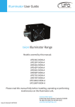
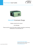
Triton Illuminator Range
Models covered by this manual:
UL-UFO75P
UL-UFO75PC
UL-UFO75PCF
UL-UFO75PCS
UL-UFO75PCR
UL-UFO100P
UL-UFO100PC
UL-UFO100PCF
UL-UFO100PCS
UL-UFO100PCR
Please read this manual fully before installing, operating or performing
maintenance on the illuminator unit.
Universal Fiber Optics LLC,
Issue 2 | Revised: 19072013
6119A Clark Center Avenue | Sarasota | Florida 34238
Tel : 1 (800) UFO 5554 | Tel : (941) 343 8115
www.fiberopticlighting.com
INTRODUCTION
Thank you for purchasing this UFO Illuminator.
Please read these instructions fully before connecting your unit to the electrical
supply, and keep them for future reference.
The UFO Triton range of illuminators are compact tungsten halogen illuminators,
suitable for use with polymer fiber.
The Triton is suitable ONLY for use in countries with 120VAC mains electrical
supplies.
The Triton features low noise and heat output, an optional factory installed 6 color
colorwheel and is available with a choice of two lamp sizes - 75W and 100W.
IMPORTANT
THIS PRODUCT MUST BE INSTALLED IN ACCORDANCE WITH THE APPLICABLE
INSTALLATION CODE BY A PERSON FAMILIAR WITH THE CONSTRUCTION AND
OPERATION OF THE PRODUCT AND THE HAZARDS INVOLVED.
Do not operate without complete lamp enclosure in place or if lens is damaged.
KEEP HARNESS IN PLACE WHEN IN OPERATION.
CAUTION: Hot surface. Keep away from curtains and other combustible
materials.
WARNING: RISK OF FIRE/INJURY TO PERSONS. Keep away from combustibles.
Unplug to change lamp. Do not touch lamp.
WARNING: RISK OF FIRE. Do not place lamp where the overhead surface is closer
than 200mm (8") to the light source.
1
Triton Illuminator Range
IMPORTANT SAFETY INFORMATION
INSTRUCTIONS PERTAINING TO A RISK OF FIRE, ELECTRIC SHOCK OR INJURY TO
PERSONS
IMPORTANT SAFETY INSTRUCTIONS
Lighted Lamp is HOT:
WARNING – To reduce the risk of FIRE, ELECTRIC SHOCK OR INJURY TO PERSONS:
1. Unplug and allow to cool before replacing lamp.
2. Lamp gets HOT quickly! Only contact plug when turning on.
3. Do not touch hot lens, guard, or enclosure.
4. Do not remain in light if skin feels warm.
5. Do not look directly at lighted lamp.
6. Keep lamp away from materials that may burn.
7. Use only with a 100W or smaller lamp.
8. Do not touch the lamp at any time. Use a soft cloth. Oil from skin may damage
lamp.
9. Do not operate product with missing or damaged guard, lamp containment
barrier, lens or fiber-optic harness.
SAVE THESE INSTRUCTIONS
• Always disconnect the unit from the power supply before opening or attempting to
perform any work on it.
• UNIT MAY GET HOT - always allow unit to cool down before handling or moving it.
• Do not touch or attempt to remove the lamp while it is hot.
• Ensure that the power supply is correct for the unit before powering it up.
• Always ensure that the unit is properly GROUNDED.
• Do not expose the unit to rain or moisture.
• Keep away from all combustible materials.
• Never attempt to tamper with the wiring or other internal components.
• Keep the unit away from gas, oil and any other flammable or explosive materials.
Universal Fiber Optics
2
ILLUMINATOR LAYOUT
3
Item
Description
A
Lamp / Colorwheel access hatch
B
Fiber port
C
Cooling fan
D
Power LED
E
Power input connector & fuse holder
F
Secondary power connector for the following options:
- Female IEC - Power connector for remote colorwheel switch
- Male IEC - Power connector for separate feed colorwheel models
- Switch - Start and stop colorwheel
- Blank Plate - Single feed colorwheel
Triton Illuminator Range
INSTALLATION GUIDE
In order for the Triton illuminator to function safely and efficiently it must be
installed according to this user manual. Please read all sections thoroughly
before switching on the illuminator.
POWER SUPPLY REQUIREMENTS
Before plugging in the unit, please make sure that the supply is correct. Failure to do
so could cause the unit to malfunction. The unit requires a 120VAC, 60Hz supply and
it MUST BE GROUNDED. The illuminator power supply units are provided with a
cordset fitted with a standard 3-pin plug.
POSITIONING THE UNIT
The Triton illuminator is only suitable for horizontal mounting, supported by its four
mounting feet.
Verify that the supporting structure can safely bear the weight of all installed units,
cables and any other equipment.
Universal Fiber Optics
4
INSTALLATION GUIDE (Continued)
CONNECTION
There are 2 or 3 connections required, depending on the model - the fiber port and
the line voltage power supply are required to be connected on all models. On units
with a remote switch to control the colorwheel, that should also be connected.
Connect and secure the fiber optic connector to the fiber port before connecting the
electrical supply or the remote switch. Never run the illuminator with the fiber
connector unplugged.
After installing and connecting the unit as described above, plug the power lead into
the line voltage supply and switch on. The illuminator will start up automatically.
Light will be output from the port connector and out through the fiber harness.
If no light is produced, please consult the TROUBLESHOOTING section in this
manual.
CLEARANCE / VENTILATION
It is recommended that a gap of 200mm (8") or more is left around the unit. This is to
allow air to circulate and prevent overheating. The location must have free
ventilation.
COLORWHEEL
Colorwheel control depends on the model variation purchased:
UL-UFO-P - No colorwheel is fitted.
UL-UFO-PC - The colorwheel rotates continuously.
UL-UFO-PCS -The colorwheel can be switched on or off using the built in switch.
UL-UFO-PCR - The colorwheel can be switched on or off using the remotely located
switch which is supplied with the unit.
UL-UFO-PCF - The colorwheel is controlled by a secondary mains electrical feed. It
can be started and stopped on any colour by simply switching the
power on or off.
5
Triton Illuminator Range
MAINTENANCE
LAMP REPLACEMENT
1) Unplug unit from electrical supply and
allow to cool.
2) Remove the single screw (A) which
secures the unit’s lamp access hatch.
3) Open the lamp access hatch and you
will see the lamp sitting in its holder
and attached to a ceramic plug (B).
4) With the lamp still attached to the
ceramic plug, pull it upwards and out
of its holder (C).
5) Pull the ceramic plug from the end of
the old lamp (D).
6) Connect the new lamp to the
ceramic plug making sure that you
use a lamp of the same
specification as to that which was
removed. Also make sure not to touch
the front of the lamp.
7) Slide the lamp back into its holder.
8) Close the lamp access hatch and
secure with the retaining screw.
Universal Fiber Optics
6
MAINTENANCE (Continued)
FUSE REPLACEMENT
1) Unplug unit from electrical supply
and allow to cool.
2) The fuse holder (A) is located under
the mains power input socket.
3) Using a small screwdriver, carefully
insert it into the slot on the top of the
fuse holder (B), and prise outwards.
4) The fuse can now be unclipped from
its holder and replaced. A spare is
provided inside the storage
compartment at the rear of the
holder.
5) Slide the fuse holder back into its slot
until it clicks into place.
CLEANING THE UNIT
Disconnect unit from power supply and allow to cool before attempting any
cleaning of the unit.
The body of the unit can be cleaned with a soft, damp cloth - do not use any
abrasives on the unit.
The fans and vents should be kept clear be periodically blowing them out with
compressed air.
Non-abrasive glass cleaner can be used to clean the glass lens inside the unit.
7
Triton Illuminator Range
MAINTENANCE (Continued)
REMOVING THE COLORWHEEL (MODELS UL-UFO-PC)
On units with a continuously revolving colorwheel, the wheel may be removed by the end
user to give static white light output.
1) Unplug unit from electrical supply and
allow to cool.
2) Remove the single screw (A) which
secures the unit’s access hatch.
3) Open the access hatch and you will
see the colorwheel mounting rod is
secured with a single screw through a
brass bush. (B).
4) Remove the screw and carefully pull
the rod towards the front of the
illuminator. Be careful to avoid
damage to the colorwheel. Remove
the colorwheel and rod from the
illuminator.
5) Close and secure the access hatch.
WIRING TO AN EXISITING SWITCH (model UL-UFO-PCR only)
Triton models UL-UFO-PCR are
supplied as standard with a colorwheel
control switch on a flylead, which is powered
by the illuminator. In cases where it is
required to control the illuminator with an
existing switch, the supplied switch can be
cut from the fly lead and this lead can be
used to wire into the existing switch.
Please see the wiring diagram on the left for
connection details.
IMPORTANT - A maintenance record table is provided overleaf for the purposes of
recording ALL maintenance undertaken on the lightsource, and MUST be filled in
accordingly.
Universal Fiber Optics
8
Please note that a record of all maintenance MUST be kept in the table below,
indicating what maintenance was undertaken and when.
Date
Maintenance Undertaken
TROUBLESHOOTING
Problem
Unit is completely dead Lamp and LED power
indicator are not
illuminated
Probable cause(s)
Main fuse blown
Check and replace fuse.
No power to unit
Check that power is switched on and
power supply is plugged in.
Lamp blown
Replace lamp
Thermal switch activated
LED power indicator & fan
are on, but no light is output
Poor light output
Lamp going on & off
randomly
Colorwheel not rotating
(UL-UFO100PCF)
9
Triton Illuminator Range
Remedy
Allow unit to cool for 5 to 10 minutes and
investigate reason for
overheating
Lamp wires are not
connected
Check plug connection - ensure lamp is
properly seated in its holder and the pins
are fully mated
Lamp needs replacing
Replace lamp
Unit needs cleaning
Clean glass lens
Incorrect power supply
Ensure power supply is 120VAC 60Hz
Fiber port connector not
plugged in correctly
Ensure fiber port connector is plugged in
correctly, and that the screw is tightened
up properly
Unit is overheating
Allow unit to cool for 5 to 10 minutes and
investigate reason for
overheating
Separate feed fuse blown
Check and replace fuse
No power to unit
Check that separate feed power is
switched on and supply is plugged in.
TECHNICAL SPECIFICATIONS
Description
75W
100W
Port connector size
Fiber type
30mm
Glass/PMMA
30mm
Glass/PMMA
Line voltage
120 VAC 60Hz
120 VAC 60Hz
Lamp power
Input power @ 120VAC
75W
82.5VA
100W
100VA
Running current @ 120VAC
0.75A
1.0A
Min. ambient temp.
Thermal protection
-20°C
40°C
Thermal switch
-20°C
40°C
Thermal switch
Fan type
80mm crossflow
80mm crossflow
Main fuse
2A
2A
Lamp type
Tungsten halogen
Tungsten halogen
Lamp model
EYF
Osram 64637
Lamp colour temp.
3000k
Indoor / dry
Sheet steel
Black
279x153x121mm
3.7kg
3000k
Indoor / dry
Black
Black
279x153x121mm
3.7kg
Max. ambient temp.
Operating environment
Material
Color
Size
Weight
Universal Fiber Optics
10
Universal Fiber Optics LLC,
6119A Clark Center Avenue | Sarasota | Florida 34238
Tel : 1 (800) UFO 5554 | Tel : (941) 343 8115
www.fiberopticlighting.com