1
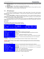
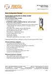
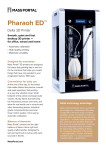
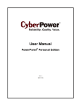
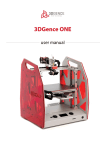
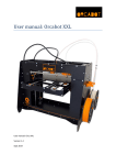
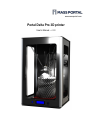
www.massportal.com Portal Delta Pro 3D printer User’s Manual – v1.0 www.massportal.com Welcome to the world of 3D printing! Thank you for your purchase of the Mass Portal 3D printer – we hope that it will serve you well and even exceed your expectations. Mass Portal strives to deliver quality products, which will ease your work and make your life even more interesting. Please take your time to study this guide thoroughly to enable the most flawless experience with your new 3D printer. We can assure you that it will make your setup and work much more easy. Have fun! Please note that the pictures in this manual may slightly differ from the product or software you have, because we are constantly improving and updating our products. Table of contents 1. Introduction........................................................................................................................................3 1.1. User manual ...................................................................................................................................3 1.2. Warranty.........................................................................................................................................3 1.3. Safety .............................................................................................................................................3 1.4. Protection .......................................................................................................................................3 2. General description of the printer ......................................................................................................4 2.1. Visual .............................................................................................................................................4 2.2. Main characteristics .......................................................................................................................5 2.3. Package contents ............................................................................................................................5 2.4. Other optionally needed but not included tools .............................................................................5 3. Usage .................................................................................................................................................6 3.1. Setup...............................................................................................................................................6 3.2. Configuration .................................................................................................................................6 3.2.1. Driver..........................................................................................................................................6 3.2.2. Repetier-Host software ...............................................................................................................7 3.2.3. Windows.....................................................................................................................................9 3.3. Insertion and retraction of plastic filament ..................................................................................10 3.4. Calibration ....................................................................................................................................11 3.5. Repetier-Host usage .....................................................................................................................12 3.5.1. Object placement ......................................................................................................................12 3.5.2. Object slicer ..............................................................................................................................13 3.5.2.1. Slic3r slicer ...........................................................................................................................13 3.5.3. G-Code Editor ..........................................................................................................................22 3.5.4. Manual Control.........................................................................................................................23 3.5.5. Main menu ................................................................................................................................24 3.6. LCD control panel ........................................................................................................................26 3.7. Maintenance .................................................................................................................................27 2 www.massportal.com 1. Introduction 1.1. User manual This user manual includes such chapters as: Introduction, General description, Usage and Printing of 3D objects. Please study this manual carefully before connecting, starting and using your printer and use your device according to these instructions. Save this manual for future reference and use whenever needed. Whenever you need additional clarification or information regarding the use of your Mass Portal 3D printer, feel free to browse our support website http://massportal.com/en/support/ or contact us by sending an e-mail to: [email protected]. 1.2. Warranty For individual users warranty time is 1 to 2 years (depending on country, but not less than the minimum required by the state’s law), for juridical entities (companies) the warranty is 1 year from the date of purchase. The warranty does not cover the [open-source] software. You need to carefully follow the instructions and recommendations from the User’s manual and you must be able to present a proof of purchase upon request to be eligible for warranty service. 1.3. Safety To avoid burns and physical damage do not touch the printer’s head, heating plate or moving parts unless the printer has been completely turned off and the heating parts (extruder head, heating plate) has been cooled enough (to room temperature or less). The printer, filament and cabling must be placed so that it cannot be unintentionally touched or hooked by clothing. If you need to clean the heating bed or the extruder use a clean paper wipe or kitchen towel. Warning! Printing surface is made from glass which can crack rather easily so be very careful with it. The heating bed can be sprayed lightly with non-flammable consumer plastics or glass cleaner and then wiped off with a clean wipe. The screws which hold the heating bed must not be overtightened because it may crack when it heats up. Avoid impacts and putting heavy objects on the heating bed or other parts. Warning! When printing especially with ABS plastic it will lightly emit fumes and smell so the premises where the printer is located must be well ventilated, but must avoid draught. If the plastic is being cooled too rapidly it may warp. If the plastic is burned it will emit toxic fumes. Warning! The printer must not be left unattended with children. This printer is not really a toy (for children) and therefore children must always be accompanied and supervised by an adult when using this product. Do not leave the printed objects, other plastic parts and tools unattended in the reach of small children to avoid harm and choking hazard. Be careful when tooling printed objects. Warning! Do not touch printer’s moving or heated parts when the printer is turned on or hasn’t cooled enough. I.e. please use common sense when working with the printer and always make sure that your actions are well justified. In case of doubt or further questions please contact us by e-mail [email protected]. 1.4. Protection The printer is intended to be used only indoors. The ambient temperature must be between 15°C/59F and 30°C/86F (including). When working outside this temperature range the printed object may not print so well. The Mass Portal 3D printer under no circumstances must be subjected to high levels of humidity, excess heat, water, frost or other condition which may damage the electronics or mechanical parts. To avoid clogging of extruder it must always reside at least 0.2mm above the printing surface. The extruder is intended to be heated up to 250°C/482F. Prolonged exposure at or above the maximum temperature may damage the printer’s head. 3 www.massportal.com 2. General description of the printer 2.1. Visual 10 11 9 7 4 X axis 8 5 1 1) 2) 3) 4) 5) 6) 7) 8) 9) 10) 11) Y axis Z axis 6 On/Off switch; LCD display for standalone operation; Rotary switch for controlling the printer; USB port, MicroSD slot, RESET button; Power supply AC 110-240V; Plastic filament reel and holder; Plastic filament supply motor; Printing surface - heated bed; Printing head with fans for cooling of PLA plastic; Timing belt adjustment screws (two on each axis); Adjustment screws for the printer head (one on each axis). 4 2 3 www.massportal.com 2.2. Main characteristics Printing technology Mechanical technology External dimensions Weight Case Case color Printing dimensions Printing surface Printing head Printing materials (filament) Filament diameter Printing layer height Extruder Max speed Tolerance at max speed Power supply Stepper motors Timing belts Control board Software 2.3. 2.4. Fused Deposition Modeling Delta robot ~420x400x720 mm (width x depth x height) ~13,5 kg Aluminium and plexiglass Black, transparent 210x210x260 mm Glass, heated up to 120°C Up to 250°C PLA, ABS, PET, PVA plastic 1.75 mm From 0.05 to 0.3 mm 0.4 mm 400 mm/s +/- 0.3 mm 110-240 VAC to 12VDC 200W NEMA 17 GT2.0 Megatronics v2.0 with USB connection, MicroSD card reader and LCD display Repetier-Host and Repetier-Firmware (http://www.repetier.com) Package contents User’s manual (this one); USB cable 1.8 m; AC power cable 220V 1.8 m; One reel with PLA filament 1 kg; Reel holder; MicroSD card; Kapton tape (50 mm wide) for the printing surface (heated bed). Other optionally needed but not included tools Computer for controlling the printer and generating the G-code; Knife, file, sandpaper – for tooling and trimming the 3D printed objects; Paper tissues – for cleaning the printing surface and extruder; Glass or plastic cleaner – for cleaning the printing surface; Screwdriver with H2.5 bit – for removing the heating bed and calibrating the printer. 5 www.massportal.com 3. Usage 3.1. Setup After removing the printer from packaging, remove the safety straps and fastenings (where applicable). NB! By powering on the printer with the safety fastenings on you will most likely damage the printer! Printer then must be placed on flat and stable surface. (Preferably out of reach of small children and pets). Make sure that the printer is not wobbling and is completely stable. Insert the reel holder in the slot on the back of the printer. Place the filament reel on the holder clock-wise (with the filament thread on the left side pointing upwards). Put the filament thread in the hole from the back and feed it in the plastic filament supply motor as shown in the picture in chapter 3.3. Connect the printer with computer using the supplied USB cable. Connect the mains power supply cable accordingly and press the On/Off button on the front panel to turn the printer on. The button, printer’s inner lighting and LCD backlight should turn on automatically when the printer is turned on. When the extruder is heating up you will hear cooling fans turn on. 3.2. Configuration 3.2.1. Driver For the first time when the printer is connected to a computer running Windows Vista or newer Windows operating system it will automatically find and install correct drivers and make a connection to the printer. To make sure that the drivers are correctly connected, open Device Manager by clicking on the Start Menu, type in devmgmt.msc and press Enter. You can run the same command from the Windows Command Prompt. In the Device Manager click on Ports (COM & LPT) and there you should find an entry called USB Serial Port (COMX) Where “X” represent your current port number assigned for the printer. If you do not see the entry and are sure that physical connection between the printer and a computer has been made, you will have to install the drivers manually. Please visit the following website http://www.ftdichip.com/Drivers/VCP.htm and download the correct driver for your operating system. Please note that for simplified installation you can download setup executable from the website’s Comment section. After verifying that the correct drivers have been installed, double-click on the corresponding entry USB Serial Port (COMX) then click the Port Settings tab and change Bits per second: 9600 to the maximum 921600 and then click OK. This will allow you to send data from your computer to printer and back at maximum speed. 6 www.massportal.com 3.2.2. Repetier-Host software Download the newest Repetier-Host software version from http://www.repetier.com/download/ for your operating system, install and run it. Follow the following steps to set the software up with your new Mass Portal 3D printer. For supplemental information regarding installation and configuration please visit http://www.repetier.com/documentation/repetierhost/rh-installation-and-configuration/. 7 www.massportal.com 2 1 3 1 1 1 1) First choose your language from the Config->Language menu. 2) You need to configure Printer settings to connect to your printer. Please make the following changes as shown in the pictures. Press Apply after making changes in each of the tabs. 3) Press the Connect button to connect to your printer. If it becomes green it means that the connection is successful and the printer is ready for work. 8 www.massportal.com 3.2.3. Windows Most of the modern operating systems have so-called Sleep mode. The process of 3D printing is not blazingly fast and may take several hours. Therefore it is recommended to disable this mode so that the computer stays awake when printing. On a computer running MS Windows you can do it by opening Power Options (Start menu → type powercfg.cpl and press Enter) 1) 9 www.massportal.com Change from Balanced to High performance and click Change plan settings. Click Change advanced power settings in the Edit Plan Settings window. 2) Find the Hard disk entry, open the Turn off hard disk after sub-entry and change the setting to 0 and press OK. 3.3. Insertion and retraction of plastic filament To insert the plastic filament follow steps below. 2 3 1) Filament tensioner screw. Always make sure that the tensioner is released by turning the screw with your fingers outwards (counter-clockwise) before inserting or removing filament. After inserting the filament adjust the tensioner by turning the screw clockwise until it feels tight, but do not over tighten it. It must move evenly when the following commands from Repetier-Host Manual Control tab are run: Extrude or Retract. Please run the above commands only when the head has been warmed to at least 170°C to avoid motor or tensioner damage. 2) Plastic filament. We use plastic filament with 1.75 mm in diameter. Manual insertion and retraction is done from the back of the printer in the dedicated hole. 3) Pipe binding. In case the tip of the filament has melted so wide that it is unable to remove it, please detach the binding from the pipe and snip the melted filament tip using pliers. After that you will be able to remove the filament. The pipe can be removed from the binding only when the base of the pipe is squeezed together and then pulled outwards. 10 www.massportal.com 3.4. Calibration Pipe binding 1 1 Extruder 2 1 2 1 Printing surface 1) Timing belt adjustment. Use the two screws at the top to adjust the timing belt. By turning the screws clockwise the timing belt is tightened, but by turning them counter-clockwise the timing belt is released. The screws must both be turned equal amount of turns. You can use a marker to mark the position of screws. The timing belts on each axis must be checked by hand – it must be able to push them lightly together, but they must not be too tight or too loose. 2) Extruder gap height in relation to printing surface. In case the printing head’s extruder is not at equal height from every position against the printing surface, it must be calibrated. One of the symptoms is uneven adhesion of the first extruded layers when printing a 3D object. Use the screws on top of each axis sliders (refer to illustration in chapter 2.1 for axis labels). By turning the screw clockwise the gap between extruder and printing surface is extended, by turning it counter-clockwise the gap is reduced. It is rather likely that the calibration must be made after changing the extruder or after transportation. To ease the calibration use Scripts from G-Code Editor in the Repetier-Host software: Script 1 G1 X-100 Y-100 Z0.1 F4000; place near the X axis column Script 2 G1 X100 Y-100 Z0.1 F4000; place near the Y axis column Script 3 G1 X0 Y100 Z0.1 F4000; place near the Z axis column Script 4 G1 X0 Y0 Z0.1 F4000; the center of the printing surface You can run these scripts by pressing Ctrl+Alt+[Num] where [Num] is the script number. By sending each script command you can check the gap at the corresponding head placement. It must be 0.1 mm. You can check the height by placing a piece of common plain paper between the extruder and a printing surface (before sending the command). Move the paper around and notice the resistance – if it is unable to move it means that the gap is too tight, if it is too easy to move the paper under the extruder then the gap is too big. Adjust the screws accordingly. Note that one full turn of a screw moves the slider by 0.5 mm, but the ratio between the turns of a screw and the extruder’s gap is not exactly 1:1. 11 www.massportal.com NB! Keep your hands and fingers clear from the printing surface before sending script commands or moving head manually. Make sure that it is unable to move the head accidently when calibrating or checking status of the printer’s inner parts to avoid damage! 3.5. Repetier-Host usage 3.5.1. Object placement 4 1 3 1 1 2 1 6 1 7 1 8 10 9 1 1) 2) 3) 4) 5) 6) 7) 8) 5 1 11 1 12 1 Export – saves the changed object as an STL or OBJ file; Add object – add new 3D objects. You can add one by one or even several at a time; Remove object – remove each selected object or use Delete button on keyboard; Copy object(s) – make several copies of the selected object; Autoposition – positions objects on the surface. Works only when there are more than one object; Center object – center each selected object in the center of the plate; Drop object – automatically position each selected object on the Z axis ground level; Object information – show detailed information about the selected object(s) like volume, dimensions, etc.; 9) Objects – lists all objects added to the project as filenames. Select individual filename to perform actions with it; 10) Coordinates – move the object on the printing surface by changing ±X, ±Y and ±Z values; 11) Scale – change the object’s size by adjusting the value in the X field. The value 1 sets the object to its original size; 12) Rotation – rotate each object according to your needs by degrees (0 – 359) 12 www.massportal.com 3.5.2. Object slicer 3 2 1 4 Created ans saved profiles 1) Slicer – select your preferred 3D object slicer; 2) Slice with [Slic3r] – slice the object(s) with predefined profiles using the slicer of your choice (“Slic3r” by default). Slicing means converting 3D object to G-Code which is read by the printer; 3) Kill Slicing – stop the slicing process using this button; 4) Configure – opens selected slicer’s configuration window. 3.5.2.1. Slic3r slicer Slic3r is one of the slicer programs which converts a 3D objects in layers and generates G-Code which contains coordinates and settings for the printer on how to exactly print a 3D object. The quality of the printed object greatly depends on these settings. For each Settings type (Print Settings, Filament Settings, Printer Settings) you can create and change as many profiles as you like and select them in the Slicer tab from main window of Repetier-Host. Note: You can view description of each function just by hovering cursor over it. 13 www.massportal.com Create and save many profiles Layer height: the height of each layer for the 3D printed object, it should be between 0.05-0.3 mm; First layer height: height of the first layer – set it to at least 0.2 mm to get better grip to the printing surface; Perimeters (minimum): how many lines should be made at the 3D object’s perimeter making a shell. Usually 2-3 is enough; Solid layers: number of solid layers at the top and bottom of the object. If set to 0 layers will be empty. Usually 2 - 3 at 0.2 – 0.3 mm layer height, for 0.05 – 0.1 mm layer height use ca. 6 - 8; Avoid crossing perimeters: Optimizes printing path to almost avoid crossing the perimeter. Usually not used as it prolongs the printing and G-Code generation time. Randomize starting points: select to have the starting point of each layer at a different place instead of one; External perimeters first: usually not used; 14 www.massportal.com Fill density: how much should the object be filled up. 1 means 100% and gives a solid object, but it takes much more time to make one. For partially filled objects use values between 0.1 and 0.9 which corresponds to 10% and 90%. Use 0 to get empty object with just the outer shell; Fill pattern: choose a pattern for the object to be filled up with; Top/bottom fill pattern: you can select different pattern for top and bottom layers; Combine infill every: how many layers to combine together. By setting the value above 1 you can save time and increase printing speed; Only infill where needed: automatically calculate where the infill is needed; Solid infill every: usually not used, but can increase structural strength for larger, partially filled objects; Fill angle: choose an angle at which the infill walls are created; Solid infill threshold area: 3D objects will have solid infill if their cross section is smaller than the given value (e.g. 7x10mm); Only retract when crossing perimeters: does not waste time on retracting the filament, if the plastic thread will not be visible. (i.e. in the inner layers of the object) ; Infill before perimeters: Usually not used as it creates the perimeters last and therefore does not guarantee smooth outer surface; 15 www.massportal.com Perimeters: printing speed for normal perimeters – usually about 50–100 mm/s; Small perimeters: If the radius is <=6.5 mm, decrease the Perimeters speed usually to 50-80%; External perimeters: printing speed for outer perimeter, recommended as above - 50-80% from Perimeters; Infill: how fast to print the infill. Can be set to 60-120 mm/s as it mostly won’t be visible; Solid infill: Printing speed for solid layers should be less and therefore more accurate. Recommended 50-80% from Infill; Top solid infill: same as the previous setting, but for the top layer. Also should be 50-80% from Infill; Support material: recommended 30-60 mm/s for the support material printing; Bridges: recommended 30-60 mm/s for the bridge printing; Gap fill: smaller gaps should be filled a bit slower – 20-40 mm/s; Travel: traveling speed of the printer head, 200-400 mm/s is recommended; First layer speed: print the first layer at about 30-40% of the general speed to get better adhesion to the printing surface. NOTE! By using too fast printing speeds the quality of printed 3D objects may decrease significantly. Please use the recommended values or lower ones to get better printing results 16 www.massportal.com Loops: how many loops to print around the object before printing itself. This allows to get an even flow of filament. Usually 1 to 3 is enough; Distance from object: how far should these loops be printed. 5-6 mm is usually optimal; Skirt height: loop height in layers. One layer is OK most of the time; Minimum extrusion length: print so many layers to extrude the specified minimum of filament in millimeters; Brim width: addition of filament on the first layer around each printable 3D object to get a better grip. 3-5 mm usually is enough when needed. Generate support material: enable or disable generation of support material usually for objects with relatively large overhangs and outward slopes which are at more than 45 degree angle/ as calculated by the program/ or specified by the next setting; Overhang threshold: 0 for automatic calculation. Set 45 for optimal manual value. Enforce support for the first: number of layers from bottom to be extra-enforced (regardless of the settings above). Good for smaller objects which are standing on one small leg or similar – to get better adhesion to the printing surface; Raft layers: “push” the printable object upwards by generating specified amount of raft layers; Pattern: pattern of choice for raft and support materials; Pattern spacing: use lower value to get better support for flat surfaces; 17 www.massportal.com Pattern angle: adjust the support material pattern angle; Interface layers: add extra layers where supports will be attached; Interface pattern spacing: lower value gives denser interface filling. Complete individual objects: use when printing multiple objects simultaneously. Check to complete each object’s layer before going to work on another’s. Default extrusion width: the width of one extruded and printed layer’s line. It may differ a bit from layer to layer. Also depends on the width of extruder (0.4 mm). Set to 0 for automatic calculation. Bridge flow ratio: change only when experimenting/needed to less or more than 1. Increases or decreases the flow of filament when building bridges. Threads: set this accordingly to your computer’s CPU threads to get better performance but larger memory consumption for object slicing. Resolution: set the value above 0 mm to get faster printing but less details/texture. 18 www.massportal.com Diameter: the width of filament diameter. May differ a bit in reality for lower quality filaments. Set 1.75 mm for Mass Portal printers; Extrusion multiplier: normally set to 1, but can be adjusted if the extrusion flow is not as needed; Extruder: change the extruder’s temperature for first and all other layers. Depending on printing speed and material sett 180-230°C for PLA and 220-240°C for ABS. The faster you print the more heating will be needed. Remember that the maximum temperature for the extruder is 250°C, do not use it at or above maximum temperature for prolonged periods; Bed: temperature of heating bed (printing surface) for the first and rest of the layers. Use 60-70°C for PLA and 100-110°C for ABS. Remember that maximum for the heated bed is 120°C. Keep fan always on: may be useful for printing with PLA, but not recommended for ABS as it will always cool the object when printing; Enable auto cooling: uses the cooling fan(s) automatically under 3D printing – recommended to use this option. When printing with ABS set Fan speed and Bridges fan speed to zero. 19 www.massportal.com Bed size: size for the heated bed. 210x210 mm for Portal Delta Pro and 150x150 mm for Portal Delta; Print center: depending on printer but usually 0; Z offset: use this in case you need to adjust the gap between extruder and printing surface without calibration. Use negative value to decrease the gap, but positive value in millimeters to increase the gap; Extruders: number of extruders, depending on printer. Currently set to 1; You can use custom G-Code commands to add at the beginning and end of generated G-Code for the object. 20 www.massportal.com Nozzle diameter: diameter in millimeters for the extruder’s nozzle. Normally 0.4 mm; [Retraction] Length: set the length of raw filament to be retracted when retraction command is sent. 4 5 mm is optimal; Lift Z: how high should the extruder be lifted up above the object(s). Normally 1 - 1.5 mm; Speed: the retraction speed of the filament. 30 - 50 mm/s is recommended; Extra length on restart: rarely needed. Use when there is no or very little filament extruded after continuing the layer on different spot; Minimum travel after retraction: do not retract the filament if the head has to move less than the specified value; Retract on layer change: usually needed to get prettier perimeters; Wipe before retract: tries to minimize blobs whenever retracting. Usually not needed. 21 www.massportal.com 3.5.3. G-Code Editor 1 2 3 1) G-Code – Here are all the generated G-Code commands. You can make corrections, copy, paste and save. Depending on the slicer program used, you may find the calculated length and volume of the filament to be extruded for the object 2) Visualization – View the whole sliced object, each layer or layer by layer; 3) Stats – view layer count and estimated printing time. 22 www.massportal.com 3.5.4. Manual Control 1 4 3 2 5 6 7 9 8 1) G-Code input field – here you can manually type and send G-Code commands. You can find more about G-Code at http://reprap.org/wiki/G-code; 2) Home position – printer head resets to the home position which is at the top of the printer. It should always be at Home position before printing objects. It is not recommended to press it (and other movement control buttons) under printing; 3) Z axis movement – use this to move printing head up or down; Each arrow has 3 or 4 separate blocks which define the amount in millimeters to move the printing head; 4) Movement of X and Y axis – move the printing head to left or right, front or back; 5) Feedrate and Flowrate – these settings can be changed under printing. E.g. use the federate to slow down the printing process (for better quality or more time for quality inspection) Flow rate will change the amount of filament being extruded; 6) Heat Extruder – to speed up the process you can heat up the extruder in case you plan to print soon, but it will heat up automatically once the printing job has started. Printing temperature can be adjusted under printing; 23 www.massportal.com 7) Heat Printbed – same as with the extruder – can be heated up in advance; otherwise it will heat up automatically if specified in G-Code. Can be adjusted under printing; 8) Extrude and Retract – NOTE: it is recommended to check the flow of filament (and if it is not clogged) before starting print to get good adhesion once the printing has started. Heat up the extruder to at least 170°C before using these buttons. The filament must flow out evenly, without interruptions to ensure good start of print. Be careful when removing the extruded test-filament – though it cools rather quickly, it may still be hot enough to burn skin. Use caution! 9) Fan – turn on or off the fan(s) at the printing head. Mostly used under PLA printing to improve the quality of print. Can be adjusted as needed. 3.5.5. Main menu 8 1 2 3 4 5 6 9 7 1) Load file – allows to load 3D object files in the following formats: *.gcode, *.gco, *.stl; *.obj, *.3ds; 2) Save Job – by pressing this button to save G-Code: Using the options as in the picture on left will save the object as a simple, text-based G-Code. If you select the third option in the dialog (Save in Binary Format) you won’t be able to make any further manual corrections in the file, but it can easily be used to print objects directly from MicroSD card. 24 www.massportal.com 3) Run (Pause) job – you can start the printing by pressing this button. If the printing has already been started, it will change to Pause job. You can pause printing if you need to change filament and even move the head around. It will resume where you left when clicking on Continue Printing; 4) Kill job – completely stops the printing and the head returns to home position; 5) SD Card – by pressing this button you will see a dialog which will allow you to manage the MicroSD in the printer; d g a b c e f a) Upload file – Upload G-Code currently loaded in the Repetier-Host software or browse the computer for pre-generated G-Code file. Due to the limited baud rate the upload by this method will take quite a while. Recommended alternative is to unmount the MicroSD card from the printer put it in a card reader attached to computer and upload sliced object file directly; b) Delete file – remove files from the memory card; c) New folder – Make a new folder to save the data; d) Run (Continue) job – using this button you can print selected file from the memory card ; e) Pause / Stop – stop current print from the memory card; f) Mound SD Card – push this button after inserting memory card in the printer (optionally use the LCD control panel directly on the printer); g) Unmount SD Card – use this before removing the memory card from printer. 6) Toggle Log – show or hide log entries at the bottom of the screen; 25 www.massportal.com 7) Show/Hide filament – show or hide filament being printed in the real time. May not be smooth on older computers; 8) Show/Hide travel – show or hide the movements of the printer head; 9) Emergency Stop – use this button to immediately stop whatever printer is doing. Useful if you notice unusual, erratic or incorrect movements of the printing head. 3.6. LCD control panel You can use the front panel on the printer to check current status of the printer, control various parameters and settings, print files standalone – without the need of external computer, do software calibration and other tasks. Use the Rotary button to navigate your way through menus. You can rotate the button clockwise or counter-clockwise to move the cursor. Press in the button to select a menu. Be careful to not turn the button while pressing it in as it may switch to other setting than wanted. For newer firmware and 3D printer versions the LCD menus may slightly differ and therefore following images and descriptions does not have to 100% accurately represent your current LCD panel setup. Use this as a general guide. Main screen. You can switch between main screens by rotating the button. It shows current/set temperature, extruder position, and status. Main menu Quick settings Position - allows to manually move printing head Extruder - turn on or off the heating for extruder, extrude filament and adjust temperature Fan speed - Change the fan speed from 0 to full speed SD Card - Mount/unmount , access the contents of memory card and print selected file Debugging - Print without actually using filament (Dry run) or turn on various info messages Configuration - configure advanced printer settings like Acceleration, Feedrate, Extruder, Calibration and others. WARNING: Incorrect settings in either software or firmware may damage the printer and even void the warranty! Use with caution! Main menu > Quick settings Home all – put the printing head in the home position (center, at the top) Preheat PLA – heats the head up to 220 C° and heatbed up to 70 C° for printing with PLA plastics Preheat ABS - heats the head up to 240 C° and heatbed up to 110 C° for printing with ABS plastics Speed Mul. :100% - adjust printing speed Flow Mul. :100% - Adjust extrusion flow rate of the filament Cooldown – stop heating both heating bed and extruder Disable stepper – cut power to stepper motors 26 www.massportal.com Main menu > Position Home all - put the printing head in the home position (center, at the top) Home X – level the printing head at the home position of X axis Home Y - level the printing head at the home position of Y axis Home Z - level the printing head at the home position of Z axis X/Y/Z Position – move the head on the corresponding axis Extr. Position > - extrude or retract filament. Note that the extruded must be warm enough for this operation. Main menu > Extruder Bed Temp.:60 C° - Set the heating bed temperature Temp. 0 :200 C° - Set the extruder temperature Extruder 0 OFF - Status of the extruder Extr. Position → - extrude or retract filament. Note that the extruded must be warm enough for this operation. Main menu > Fan speed Main menu > SD Card 3.7. Maintenance Please do regular maintenance to allow the printer to serve you well and long. Maintenance includes: Cleaning the glass printing surface – do every time before printing to assure good adhesion of 3D objects. Clean with glass or plastics cleaner and kitchen towel. If plastic has melted hard on the surface, you may use a scraper or blade, but be very careful not to cut yourself or damage the printing surface! External extruder cleaning – do every time before printing or as needed. Heat the extruder to at least 200°C, and use kitchen towel folded in many layers to wipe off excess plastic from the extruder. As always – be VERY careful and don’t hold the kitchen towel on the extruder for too long and avoid touching it with fingers. Use heat-protective gloves if needed; Cleaning and oiling of steel rods for each axis – do once in 2-3 months. Clean the rods carefully with dry paper towel from dirt and grease. Oil the rods lightly in full length. You can use mineral oil, special bearing oil or oil for bicycles; Calibration – as needed. Detailed description can be found in chapter 3.4. 27