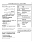
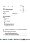
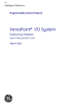
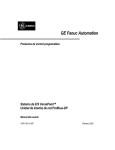
1
VersaPoint I/O Module
Analog In 16 Bit RTD 2 Channels
IC220ALG620
GFK-2013
January 2004
Module IC220ALG620 provides two-input channels for
resistive temperature sensors. It supports platinum or nickel
sensors according to the DIN standard and SAMA Directive.
In addition, CU10, CU50, CU53, KTY81 and KTY84 sensors
are supported.
Module Specifications
Housing dimensions
(width x height x depth)
12.2mm x 120mm x 66.6mm
(0.480in. x 4.724in. x 2.622in.)
Connection style
2- , 3-, and 4-wire
Operating temperature
-25°C to +55°C
(-13°F to +131°F)
Storage temperature
-25°C to +85°C
(-13°F to +185°F)
Operating humidity
75% on average. Take
appropriate measures against
increased humidity (> 85%).
Storage humidity
75% on average
Degree of protection
IP20 according to IEC 60529
Class of protection
Class 3 according to VDE
0106, IEC 60536
Power Consumption
Module with the I/O Terminal Strip plugged in
Module IC220ALG620 requires one (1) I/O Terminal Strip,
IC220TBK061, ordered separately. See the ordering
information below.
Features
Two inputs for resistive temperature sensors
Configuration of the independent channels
Three data formats
Connection of 2-, 3-, and 4-wire sensors
Communications power
UL
7.5V
Current consumption
from local bus UL
43mA, typical
I/O supply voltage UANA
24VDC
Current consumption
from analog bus UANA
11mA, typical
Total power
consumption
0.59W, typical
Ordering Information
IC220ALG620
Analog In 16 Bit RTD 2 Channels
IC220TBK061
I/O Terminal Strip with Shield, qty 5
1
VersaPoint I/O Module
Analog In 16 Bit RTD 2 Channels
IC220ALG620
GFK-2013
January 2004
Installation Instructions
Connections
High current flowing through the segment and main
power busses raises the temperature of the
components within the module. To keep the current
flowing through the potential jumpers of the analog
modules as low as possible, a separate main circuit
should be used for analog modules. If analog
modules must be used in a main circuit together with
other modules place the analog modules to the right
of the standard modules, at the end of the main
circuit.
Always connect temperature shunts using shielded,
twisted-pair cables.
Connect the shield at the module using the shield
connector clamp. The clamp connects the shield
directly to FE on the terminal side. Additional wiring is
not necessary. Isolate the shield at the sensor. ,
A 4-wire sensor can only be connected to channel 1;
only one 4-wire sensor can be connected to the
module.
During installation, ensure that no isolating voltage is
specified between the analog inputs and the bus.
Provide signals with safe isolation for the thermistor
detection, if required.
2
LED
Color
Meaning
D
Green
Bus diagnostics
Example: 2-Wire and 3-Wire Sensors
Example: 4-Wire and 2-Wire Sensors
A.
Channel 1: 2-wire sensor
A.
Channel 1: 4-wire sensor
B.
Channel 2: 3-wire sensor
B.
Channel 2: 2-wire sensor
Terminal
1.1
1.2
1.3
2.1
Signal
I1+
I1U1I2+
2.2
2.3
I2U2-
1.4, 2.4
Shield
Assignment
RTD sensor 1
Constant current supply
Measuring input sensor 1
RTD sensor 2
Constant current supply
Measuring input sensor 2
Shield connection (ch 1 and 2)
Terminal
1.1
1.2
1.3
2.1
Signal
I1+
I1U1U1+
2.2
2.3
I2+
I2-
1.4, 2.4
Shield
Assignment
RTD sensor 1
Constant current supply
Measuring input sensor 1
Measuring input sensor 1
RTD sensor 2
Constant current supply
Shield connection (ch 1 and 2)
VersaPoint I/O Module
Analog In 16 Bit RTD 2 Channels
IC220ALG620
GFK-2013
January 2004
Internal Circuit Diagram
Electrical Isolation
Protocol chip (bus logic including voltage
conditioning)
Optocoupler
Programming Data
DC/DC converter with electrical isolation
ID code
7F hex (127 decimal )
Microprocessor with multiplexer and
analog/digital converter
Length code
02 hex
Reference voltage
Input address area
4 bytes
Electrically erasable programmable readonly memory
Amplifier
Output address area
4 bytes
Parameter channel (PCP)
0 bytes
Register length (bus)
4 bytes
3
VersaPoint I/O Module
Analog In 16 Bit RTD 2 Channels
IC220ALG620
GFK-2013
January 2004
Output Data Words for Channel Configuration
The module receives two output data words. These data words can be used to configure the module. The module’s
default configuration can be used without change, or each channel can be configured independently. This configuration
setting is not saved, and must be transmitted in each logic scan.
Default channel configuration
Connection type:
Reference resistance:
Resolution:
Sensor type:
Data format:
3-wire sensors
100 Ohms
0.1 degree C.
PT 100 (DIN)
Extended diagnostics mode
The following parameters can be configured:
Sensor connection type: 2-wire, 3-wire, or 4-wire *
Value of the reference resistance
Resolution
Format for representing the measured values
Sensor type
* Only channel 1 can be configured for a 4-wire sensor. If that is done, channel 2 can only be used for a 2-wire sensor.
Configuration Diagnostics
In the default format, the following configuration errors are indicated by an error code. If the data format is changed,
extended diagnostics are not available.
After powerup, the message “measured value invalid” (error code 8004 hex) appears in the input data. After 1
second (maximum) the preset configuration is accepted and the first measured value is available.
If the channel configuration is changed, the corresponding channel is re-initialized. The message “measured
value invalid” (error code 8004 hex ) appears in the input data for 100mS (maximum).
If the configuration is invalid, the message “Configuration invalid” appears (error code 8010 hex).
Process Data Output Format
Each channel has one process data output word associated with it. You must set bit 15 of the corresponding output word
to 1 to reconfigure the channel. If bit 15 = 0, the default configuration is used. Bit 14 should always be set to 0.
4
VersaPoint I/O Module
Analog In 16 Bit RTD 2 Channels
IC220ALG620
GFK-2013
January 2004
To configure a channel, set bit 15 of that output word to 1. If bit 15 is zero, the preset configuration is active.
Bit
Assignment
Decimal Binary
Description
15
0
0
Default configuration
Configuration
1
1
Change configuration data
14
0
0
Must be zero.
13, 12
Connection
0
00
3-wire, Default
type
1
01
2-wire, if channel 1 is 4-wire, channel 2 must be 2-wire
2
10
4-wire, Channel 1 only
3
11
reserved
11 - 8
Reference
0
0000
100 Ohms, Default
resistance (in
1
0001
10
Ohms), RO
2
0010
20
3
0011
30
4
0100
50
5
0101
120
6
0110
150
7
0111
200
8
1000
240
9
1001
300
10
1010
400
11
1011
500
12
1100
1000
13
1101
1500
14
1110
2000
15
1111
3000 (adjustable)
7, 6
Resolution for
Sensor type value in bits 3 – 0 is:
sensor type:
0 - 10
13
14
15
resolution
Resolution is:
depends on
0
00
0.1 deg. C
1%
0.1 Ohm
1 Ohm
setting for
1
01
0.01deg.
C
0.1%
0.01
Ohm
0.1
Ohm
sensor type in
10
0.1 deg. F
bits 3 – 0 (see 2
Reserved
below)
3
11
0.01 deg F
5, 4
Format
0
00
Signed, 15-bit resolution with extended diagnostics. Default
1
01
12 bit resolution with 3 diagnostic bits
2
10
Standardized Format: 15 bit resolution, no diagnostics
3
11
Reserved
3-0
Sensor type
0
0000
Pt DIN, Default
1
0001
Pt SAMA
2
0010
Ni DIN
3
0011
Ni SAMA
4
0100
Cu10
5
0101
Cu50
6
0110
Cu53
7
0111
Ni 1000 (L & G)
8
1000
Ni 500 (Viessmann)
9
1001
KTY 81-110
10
1010
KTY 84
11, 12
1011,
Reserved
1100
13
1101
Potentiometer (%)
14
1110
Linear R: 0 through 400 Ohms
15
1111
Linear R: 0 through 4000 Ohms
5
VersaPoint I/O Module
Analog In 16 Bit RTD 2 Channels
IC220ALG620
GFK-2013
January 2004
Process Data Input Words
The measured input values are transmitted, per channel, to the controller. The figure below shows the sequence of the
input data words.
Channel 1
(2 bytes)
Channel 2
(2 bytes)
For each channel, the format of the input data can be independently configured in three input data formats as shown
below and on the following pages.
Default Input Data Format: Signed, 15-Bit Resolution with Extended Diagnostics
This format can be selected for each channel using bits 5 and 4 (bit combination 0 0 ) of the corresponding process data
output word. In the input data, bit 15 can be used as a sign bit; bits 14 to 0 contain the analog value.
15
14
13
12
11
10
9
Sign
8
7
6
5
4
3
2
1
Analog Value
Channel Error Codes
The default format supports extended diagnostics. Values greater than 8000H indicate an error.
Hex
Decimal
Error
8001
-32767
Over range
8002
-32766
Open circuit or short circuit (available only in the temperature
range)
8004
-32764
Measured value invalid or no valid measured value available
8010
-32752
Configuration invalid
8040
-32704
Module defective
8080
-32640
Under range
Open Circuit/Short-Circuit Detection
Open circuit is detected according to the conditions listed below:
Yes
-No
open circuit/short circuit is detected
the cable is not connected for this type
open circuit/short circuit is not detected because the measured value is valid.
Faulty Sensor
Cable
6
Temperature measuring Range
2-wire
3-wire
4-wire
Resistance Measuring range
2-wire
3-wire
4-wire
I+
Yes
Yes
Yes
Yes
Yes
No
I-
Yes
Yes
Yes
Yes
Yes
No
U+
--
--
Yes
--
--
Yes
U-
--
Yes
Yes
--
Yes
Yes
0
VersaPoint I/O Module
Analog In 16 Bit RTD 2 Channels
IC220ALG620
GFK-2013
January 2004
Significant Measured Values in the Default Data Format
The table below shows typical hexadecimal and corresponding decimal values in the default data format. Values are
shown for the different combinations of configured sensor type and resolution.
RTD inputs
Typical Input
Values
Potentiometer %
Linear R :
0 –400 Ohms
Linear R;
0 – 4000 Ohms
Hex
Decimal
0.1 degree
resolution
0.01 degree
resolution
1%
resolution
0.1%
resolution
0.1 Ohm
resolution
0.01 Ohm
resolution
1 Ohm
resolution
0.1 Ohm
resolution
8002
8001
-
open circuit
over range
-
-
400
325.12
4000
3251.2
2710
10000
1000.0
open circuit
>325.12
Over range
100.00
-
-
100.00
-
1000.0
0FA0
4000
400.0
-
400
-
4000
-
03E8
4000
-
10.00
4000
(40x R0)
-
1000.0
(10x R0)
-
-
10.00
-
100.0
00A0
10
1.0
-
1.0
-
10
-
0001
1
0.1
0.01
0000
FFFF
FC18
D8F0
0
-1
-1000
-10000
0
-0.1
-100.0
-
0
-0.01
-100.00
8080
8002
-
under range under range
short circuit short circuit
100.0
(1x R0)
-
10.0
(0.10x R0)
1
(0.01x R0)
0
-
0.1
(0.01xR0)
0
-
0.1
0.01
1
0.1
0
-
0
-
0
-
0
-
-
-
-
-
-
-
7
VersaPoint I/O Module
Analog In 16 Bit RTD 2 Channels
IC220ALG620
GFK-2013
January 2004
Standardized Input Data Format: 15 Bit Resolution, No Diagnostics
This format can be selected for each channel using bits 5 and 4 (bit combination 1 0 ) of the corresponding process data
output word. In this format, the measured value is represented in bits 14 to 0. Bit 15 is available as a sign bit.
15
14
13
12
11
10
9
Sign
8
7
6
5
4
3
2
1
0
Analog Value
Significant Measured Values in Standardized Representation Format
The table below shows typical hexadecimal and corresponding decimal values in Standardized Representation format.
Values are shown for the different combinations of configured sensor type and resolution.
Hex
Decimal
7FFF
32767
Upper limit value
+1 LSB
7D00
32000
2710
10000
000A
10
0001
1
0000
0
FFFF
-1
FC18
-1000
D8F0
-10000
lower limit value
- 1 LSB
lower limit value
-2 LSB
8
Linear R;
0 – 4000 Ohms
RTD inputs
Typical Input
Values
0.1 deg resolution
0.01 dec resolution
1 Ohm resolution
0.1 Ohm resolution
over range
over range
->2048
-
>4096
-
1000.0
1
0.1
0
-0.1
-100.0
under range
320.00
100.0
0.01
0
-1.0
-100.00
under range
2000
625
0.625
0.0625
0
-
4000
1250
0.125
0
-
open / short circuit
open / short circuit
-
-
VersaPoint I/O Module
Analog In 16 Bit RTD 2 Channels
IC220ALG620
GFK-2013
January 2004
12-Bit Input Data with Diagnostics
This format can be selected for each channel using bits 5 and 4 (bit combination 0 1 ) of the corresponding process data
output word. The measured value is represented in input bits 14 through 3. Input bit 15 is the sign bit. Bit 1 indicates open
circuit/short circuit. For an open circuit or short circuit, bit 1 is set to 1. Bit 0 indicates an over range condition. If the
measured value is outside the representation area of the process data, bit 0 is set to 1.
15
14
13
12
11
10
Sign
9
8
7
6
5
4
3
Analog Value
2
1
0
0
OC
OR
Significant Measured Values in 12-Bit Resolution Format
The table below compares typical hexadecimal and corresponding decimal values in 12-bit resolution format.
RTD inputs
Typical Input Values
Hex
Decimal
xxxx xxxx xxxx xxx1bin
0.1 deg resolution
0.01 deg resolution
Over range
(Positive value as shown in the table on next page)
2710
10000
1000.0
100.0
03E8
1000
100.0
10.00
0008
8
0.8
0.08
0000
0
0
0
FFF8
-8
-0.8
-0.08
FC18
-1000
-100.0
-10.00
xxxx xxxx xxxx xxx1bin
Under range
(Negative value as shown in the table on next page)
xxxx xxxx xxxx xx1xbin
Open circuit / short circuit
(Negative value as shown in the table on next page)
9
VersaPoint I/O Module
Analog In 16 Bit RTD 2 Channels
IC220ALG620
GFK-2013
January 2004
Measuring Ranges for Temperature Sensors
The module's measuring range for temperature sensors depends on the configured resolution. The resolution chosen
should be appropriate for the expected temperature range of the sensors, as shown in the bottom table.
Resolution
Measuring Range
0.1 degree C
-273 degrees C to +3276.8 degrees C
0.01 degree C
-273 degrees C to +327.68 degrees C
0.1 degree F
-459 degrees F to +3276.8 degrees F
0.01 degree F
-459 degrees F to +327.68 degrees F
To convert Celsius measurements to Fahrenheit, the following formula can be used in the application:
Degrees F = Degrees C x (9/5 + 32)
Input Measuring Ranges
The ranges shown below are supported for the different types of configurable input measurements. If the input data format
being used (see previous pages) supports diagnostics, input measurements that are outside the low and high limits are
reported as under range or over range.
10
Sensor Type
Pt R0 10Ω
Ω to 3000Ω
Ω DIN, Default
Pt R0 10Ω to 3000Ω, SAMA
Low Limit
-200C (-328F)
-200C (-328F)
High Limit
+850C (+1562F)
+850C (+1562F)
Ni R0 10Ω to 3000Ω, DIN
Ni R0 10Ω to 3000Ω, SAMA
-60C (-76F)
-60C (-76F)
+180C (+356F)
+180C (+356F)
Cu10
Cu50
-70C (-94F)
-50C (-58F)
+500C (+932F)
+200C (+392F)
Cu53
Ni 1000 (L & G)
-50C (-58F)
-50C (-58F)
+180C (+356F)
+160C (+320F)
Ni 500 (Viessmann)
KTY 81-110
-60C (-76F)
-55C (-67F)
+250C (+482F)
+150C (+302F)
KTY 84
Reserved
-40C (-40F)
-
+300C (+572F)
-
Potentiometer (%)
0%
4kΩ / R0 x100%
(400% maximum)
Linear Resistance: 0 through 400 Ohms
0Ω
400Ω
Linear Resistance: 0 through 4000 Ohms
0Ω
4000Ω
VersaPoint I/O Module
Analog In 16 Bit RTD 2 Channels
IC220ALG620
GFK-2013
January 2004
Measuring Errors
When measuring temperatures with resistance
thermometers, measuring errors may cause incorrect
results.
4-Wire Sensor Measurement Errors
4-wire sensors provide the most precise measurements.
3-Wire Sensor Measurement Errors
3-wire sensors provide measurements that are nearly as
precise as measurements taken with 4-wire sensors.
However, 3-wire sensors are more vulnerable to
interference in noisy environments.
A constant current is sent through the sensor via the I+ and
I- cables. Two additional cables, U+ and U-, can be used to
tap and measure the temperature-related voltage at the
sensor. The cable resistances have no effect on the
measurement.
With 3-wire sensors, the effect of cable resistance on the
measurements in the module is eliminated or minimized
by multiple measuring of the temperature-related voltage
and corresponding calculations.
11
VersaPoint I/O Module
Analog In 16 Bit RTD 2 Channels
IC220ALG620
GFK-2013
January 2004
2-Wire Sensor Measurement Errors
2-wire sensors provide cost-effective connections. The U+
and U- cable connections are not used. The temperaturerelated voltage is not directly measured at the sensor, so it
is not affected by cable resistances RL.
Measurement accuracy also increases as cable diameter
2
increases. Using cables with a diameter less than 0.5mm
(20AWG) greatly increases measurement errors:
Finally, higher ambient temperature also increases cable
resistance. However, the impact is slight.
Measurement errors can occur with 2-wire sensors as a
result of cable resistance. The following examples
describe the impact of various installation factors on
measurement accuracy. In each example, measurement
error was found for:
Calculating Cable Resistance
Cable resistance can be calculated using the following
equation:
PT 100 sensor
2
copper cable χ = 57m/Ωmm ,
temperature = 25 degrees C (77F)
In all cases, using PT 1000 sensors would improve
measurement accuracy by ten times over the PT 100
sensor, due to the higher temperature coefficient of the PT
1000 sensor:
PT 100: (α = 0.385Ω/K)
PT 1000 (α = 3.85 Ω/K)
Resistance increases with cable length, so cables should
be kept as short as possible when using 2-wire sensors.
The diagram below compares the increase in temperature
measurement error (∆T) with the increase in cable length
for cables of three different diameters.
Where:
RL
RL20l
Cable resistance in Ohms
Resistance at 20 deg. C (68F) in Ohms
Cable length in m
χ
Specific electrical resistance of copper
2
in Ωmm /m
2
A
Cable diameter in mm
0.0043 1/K
Temperature coefficient for copper
TU
Ambient (cable) temperature in deg C
Because there are two cable resistances in the measuring
system (forward and return), the value must be doubled.
The absolute measuring error in Kelvin |K| is provided for
platinum sensors according to DIN using the average
temperature coefficient α (α = 0.385Ω/K for PT 100; a =
3.85Ω/K for PT1000).
12
2
1.
Diameter = 0.14mm (AWG 26)
2.
Diameter = 0.25mm (AWG 24)
3.
Diameter - 0.50mm (AWG 20)
2
2
VersaPoint I/O Module
Analog In 16 Bit RTD 2 Channels
IC220ALG620
GFK-2013
January 2004
Tolerance and Temperature Response
Typical Measuring Tolerances at 25C (77F)
α at 100C
(212F)
2-Wire Sensors
Relative (%)
Absolute
3-Wire Sensors
Relative (%)
Absolute
4-Wire Sensors
Relative (%)
Absolute
Temperature Sensors
PT 100
0.385Ω/K
+/-0.03 + X
+/-0.26K + X
+/-0.03
+/-0.26K
+/-0.02
+/-0.2K
PT 1000
3.85Ω/K
+/-0.04 + X
+/-0.31K + X
+/-0.04
+/-0.31K
+/-0.03
+/-0.26K
Ni 100
0.617Ω/K
+/-0.09 + X
+/-0.16K + X
+/-0.09
+/-0.16K
+/-0.07
+/-0.12K
Ni 1000
6.17Ω/K
+/-0.11 + X
+/-0.2K + X
+/-0.11
+/-0.2K
+/-0.09
+/-0.16K
Cu 50
0.213Ω/K
+/-0.24 + X
+/-0.47K + X
+/-0.24
+/-0.47K
+/-0.18
+/-0.35K
Ni 1000 L&G
5.6Ω/K
+/-0.13 + X
+/-0.21K + X
+/-0.13
+/-0.21K
+/-0.11
+/-0.18K
Ni 500
Viessmann
2.8Ω/K
+/-0.17 X
+/-0.43K + X
+/-0.17
+/-0.43K
+/-0.14
+/-0.36K
KTY 81-110
10.7Ω/K
+/-0.07+ X
+/-0.11K + X
+/-0.07
+/-0.11K
+/-0.06
+/-0.09K
KTY 84
6.2Ω/K
+/-0.06 + X
+/-0.19K + X
+/-0.06
+/-0.19K
+/-0.05
+/-0.16K
0Ω to 400Ω
+/-0.025 + X
+/-100mΩ + X
+/-0.025
+/-100mΩ
+/-0.019
+/-75 mΩ
0Ω to 4kΩ
+/-0.03 + X
+/-1.2Ω + X
+/-0.03
+/-1.2Ω
+/-0.025
+/-1Ω
Linear resistance
α = Average sensitivity for the calculation of tolerance values
χ = Additional error due to connection for 2-wire sensors
Maximum Measuring Tolerances at 25C (77F)
α at 100C
(212F)
2-Wire Sensors
Relative (%)
Absolute
3-Wire Sensors
Relative (%)
Absolute
4-Wire Sensors
Relative (%)
Absolute
Temperature Sensors
PT 100
0.385Ω/K
+/-0.12 + X
+/-1.04K + X
+/-0.12
+/-1.04K
+/-0.10
+/-0.83K
PT 1000
3.85Ω/K
+/-0.15 + X
+/-1.3K + X
+/-0.15
+/-1.3K
+/-0.12
+/-1.04 K
Ni 100
0.617Ω/K
+/-0.36 + X
+/-0.65K + X
+/-0.36
+/-0.65K
+/-0.29
+/-0.52K
Ni 1000
6.17Ω/K
+/-0.45 + X
+/-0.81K + X
+/-0.45
+/-0.81K
+/-0.36
+/-0.65K
Cu 50
0.213Ω/K
+/-0.47 + X
+/-0.94K + X
+/-0.47
+/-0.94K
+/-0.38
+/-0.75K
Ni 1000 L&G
5.6Ω/K
+/-0.56 + X
+/-0.89K + X
+/-0.56
+/-0.89K
+/-0.44
+/-0.71K
Ni 500
Viessmann
2.8Ω/K
+/-0.72 + X
+/-1.79 K + X
+/-0.72
+/-1.79 K
+/-0.57
+/-1.43K
Y
10.7Ω/K
+/-0.31+ X
+/-0.47K + X
+/-0.31
+/-0.47K
+/-0.25
+/-0.37K
KTY 84
6.2Ω/K
+/-0.27 + X
+/-0.81K + X
+/-0.27
+/-0.81K
+/-0.22
+/-0.65K
0Ω to 400Ω
+/-0.10 + X
+/-400mΩ + X
+/-0.10
+/-400mΩ
+/-0.08
+/-320 mΩ
0Ω to 4kΩ
+/-0.13 + X
+/-5Ω + X
+/-0.13
+/-5Ω
+/-0.10
+/-4Ω
Linear resistance
α = Average sensitivity for the calculation of tolerance values
χ = Additional error due to connection for 2-wire sensors
Temperature Response at -25C to 55C (-13F to 131F)
For 2, 3, and 4-wire sensors: Typical = +/- 12ppm/degree C/ Maximum = +/- 45ppm / degree C.
13
VersaPoint I/O Module
Analog In 16 Bit RTD 2 Channels
IC220ALG620
GFK-2013
January 2004
Technical Data
Analog Inputs
Number
Connection of the signals
Sensor types that can be used
Standards for characteristic curves
Conversion time of the A/D converter
Process data update
Both channels with 2-wire sensors
One channel with 2-wire sensor and
one channel with 4-wire sensor
Both channels with 3-wire sensors
Two inputs for resistive temperature sensors
2, 3, or 4-wire, shielded sensor cable
Pt, Ni, Cu, KTY
According to DIN / according to SAMA
120µs typical
Depends on connection method
20mS
20mS
32mS
Safety Devices
None
Electrical Isolation
To provide electrical isolation between the logic level and the I/O area it is necessary to supply the bus module
and the sensors using a power terminal from separate power supplies. Interconnection of power supply units in
the 24V range is not allowed. (For detailed information refer to the NIU User’s Manual.)
Common potentials
24V main power, 24V segment voltage, and GND have the same potential. FE (functional earth ground) is a
separate potential area.
Isolated Voltages in the RTD Module
- Test distance
- Test voltage
7.5V supply (bus logic) / 24V supply (analog I/O)
500VAC, 50Hz, 1min.
7.5V supply (bus logic) / functional earth ground
500VAC, 50Hz, 1min.
24V supply (analog I/O) / functional earth ground
500VAC, 50Hz, 1min.
Error Messages to the Control System
Breakdown of the internal voltage supply
Yes
Failure or dropping of communications
voltage
Yes, I/O error message to the NIU module
Error Messages via Process Data
I/O error / user error
14
Yes