1
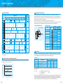
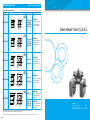
Outline of gear head
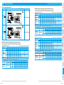
Gear head efficiency
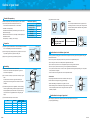
Overhung load and thrust load
Decimal
gear head
Reduction ratio
Model No.
M4GA F
3 3.6 5
6 7.5 9
10 12.5 15 18 20 25 30 36 50 60 75 90 100 120 150 180 200
72 %
61 %
52 %
10
41 %
MX6G B
MX7G B
81 %
MX8G B
81 %
75 %
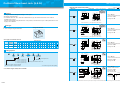
The overhung load is defined as a load applied to the output shaft in the right-angle direction. This load is
generated when the gear head is coupled to the machine using a chain, belt, etc., but not when the gear head is
directly connected to the coupling. As shown in the figure below, the permissible value is determined based on the
load applied to the L/2 position of the output shaft.
The thrust load is defined as a load applied to the output shaft in the axial direction.
Because the overhung load and thrust load significantly affect the life of the bearing, take care not to allow the load
during operation to exceed the permissible overhung load and thrust load shown in the table below.
• Overhung load and thrust load
• Permissible load list
MX9G B
MZ9G B
MY9G B
81 %
75 %
70 %
MR9G B
81 %
70 %
L
2
81 %
L
2
MX7G M
61 %
72 %
MX8G M
L
81 %
42 mm sq. (1.65 inch sq.)
F (Thrust load)
70 mm sq. (2.76 inch sq.)
80 mm sq. (3.15 inch sq.)
MX9G M
60 %
60 %
60 %
45 %
81 %
90 mm sq. (3.54 inch sq.)
MZ9G R
60 %
60 %
60 %
54 %
45 %
81 %
90 mm sq. (3.54 inch sq.)
High torque
type
for C&B motor
MX6G H
MX7G H
81 %
MX8G H
75 %
90 mm sq. (3.54 inch sq.)
70 %
Permissible
Permissible
overhung load
thrust load
N
lb
N
lb
M4GA F
1.5 3.3
20
2
4.4 15
MX6G B(A)
98 10
22
29
3
6.6
MX6G M(A)
49
5
11
MX7G B(A) 196 20
44
39
4
8.8
MX7G M(A)
98 10
22
MX8G B
294 30
66
49
5
11
MX8G M
196 20
44
MX9G B
392 40
88
98 10
22
MX9G M
294 30
66
MZ9G B
588 60 132
147 15
33
MY9G B
MR9G B
147 15
784 80 176
33
MP9G B
MX9G R
392 40
98 10
22
88
147 15
33
MZ9G R
588 60 132
Model
60 mm sq. (2.36 inch sq.)
MX6G M
MX9G R
Size
d
MP9G B
W (Overhung load)
Right-angle
type
MX9G H
MY9G H
81 %
75 %
70 %
65 %
* When the decimal gear head is used, the total efficiency is the product of gear head efficiency and decimal gear
head efficiency.
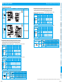
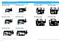
Gear head efficiency and ambient temperature
Torque reduction ratio
Calculate the actual gear head efficiency by multiplying the above-shown gear head efficiency at room temperature
by the torque reduction ratio shown below.
B-436
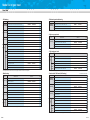
Service factor
Life expectancy of motor varies depending on load fluctuation. To determine the life expectancy, a factor called
service factor, as shown in the table below is used.First choose the appropriate service factor according to the type
of load and multiply the result by the required power to determine the design power.
• Service factor
Type of load
Constant
Light-impact
[%]
120
Medium-impact
Heavy-impact
Service factor
5 hours/day
8 hours/day 24 hours/day
Belt conveyor, One-directional rotation
0.8
1.0
1.5
Start/Stop, Cam-drive
1.2
1.5
2.0
Instant FWD/REV, Instant stop
1.5
2.0
2.5
Frequent medium-impact
2.5
3.0
3.5
The required allowable shaft torque TA of the gear head can be determined based on the service factor and actual
load torque T1:
100
TA = T1 x Sf
80
60
Typical load
–10
0
20
Ambient temperature
40 [˚C]
TA : Allowable torque of gear head (N·m)
T1 : Actual load torque
(N·m)
Sf : Service factor
Use the motor so that the allowable torque TA calculated from the formula above falls within the allowable torque range.
* Though it seems that the motor can be operated even in overload when the service factor is 0.8, note that the
service factor is defined for the allowable torque of the gear head. If the motor is operated in overload, the life of
insulator may be shortened or the motor may be burned out due to an abnormal temperature rise.
B-437