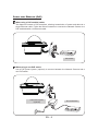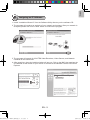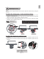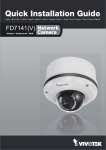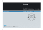
1
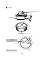
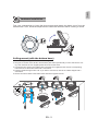
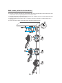
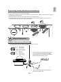
FD8361
2 MP H.264 Day&Night Vandal-proof
P/N:625010100G Ver.1.0
Copyright c 2009 VIVOTEK INC. All rights reserved.
English
Warning Before Installation
Power off the Network Camera as
soon as smoke or unusual odors are
detected.
Refer to your user's manual for the
operating temperature.
Contact your distributor in the event of
occurrence.
Do not place the Network Camera on
unsteady surfaces.
Do not touch the Network Camera
during a lightning storm.
Do not insert sharp or tiny objects
into the Network Camera.
Do not drop the Network Camera.
625010100G_QIG, FD8361_20091221_V.1.0.indd
EN - 1
1
2009/12/21
PM 05:20:54
1
Package Contents
FD8361
Bottom Base
Power Adapter
Alignment Sticker /
Ceiling Hole Template Sticker
Drill hole
Ceiling Hole Template Sticker
L-type Hex Key Wrench / RJ45 Female/Female Coupler / Slica Gel / Screws
Quick Installation Guide /
Warranty Card
Software CD
FD8361
2 MP H.264 Day&Night Vandal-proof
510000210G
P/N:625010100G Ver.1.0
Copyright c 2009 VIVOTEK INC. All rights reserved.
625010100G_QIG, FD8361_20091221_V.1.0.indd
EN - 2
2
2009/12/21
PM 05:20:57
English
2
Physical Description
Inner View
IR LEDs (18 units,
distance 20m)
Light Sensor
Rotation Adjustment
Screw
Tilt Adjustment Screw
Pan Adjustment Screw
NTSC/PAL Video Output
Switch
Vari-focal Lens
(f= 3~9 mm)
SD/SDHC Card Slot
Status LED
Reccessed Reset
Button
625010100G_QIG, FD8361_20091221_V.1.0.indd
Focus Controller
Zoom Controller
BNC Video Output
N.C.
N.C.
N.C.
V
AC24
V
AC24
General I/O Terminal Block
Ethernet 10/100 RJ45 Plug
Audio Out (green)
Microphone In (pink)
Power Cord Socket (black)
Ground
Operating environment: -20° ~ 50°C
When the temparature inside the Network
Camera reaches over 50°C, the fan will operate
automatically; when the temparature inside the
Network Camera drops to 0°C, the heater and fan
will both operate automatically.
Fan
Heater
EN - 3
3
2009/12/21
PM 05:21:06
Outer View
IP66-rated Vandal-proof
Dome Cover
N.C.
N.C.
N.C.
AC24V
AC24V
Camera Base
c
b
a
IP66-rated Vandal-proof
Bottom Base
c
Record the MAC address under
the camera base before installing
the camera.
Network Camera
Model No: FD8361
RoHS
V I
MAC:0002D1083236
CLASS A
a
This device complies with part 15 of the FCC rules. Operation is subject to
the following two conditions:
(1)This device may not cause harmful interference, and
(2) this device must accept any interference received, including interference
that may cause undesired operation.
Pat. 6,930,709
Hole a~c:
Holes to secure the bottom base.
625010100G_QIG, FD8361_20091221_V.1.0.indd
Made in Taiwan
b
EN - 4
4
2009/12/21
PM 05:21:08
English
3
Hardware Installation
First, use a screwdriver to loose the three screws and detach the dome cover from the
camera base. Then, follow the steps below to install the camera to either a ceiling or a wall.
N.C.
N.C.
N.C.
AC24V
AC24V
Ceiling mount (with the bottom base)
1. Attach the supplied alignment sticker to the ceiling.
2. Using the 10 circles on the sticker, drill at least 2 pilot holes symmetrically on each side into the ceiling. Then hammer the four supplied plastic anchors into the holes.
3. Through the four holes on the bottom base, insert the four supplied screws into the corresponding
holes and secure the bottom base with a screwdriver.
4. Feed the cables through hole A or B. If you want to use hole B, remove the rubber stopper with a
screwdriver.
5. Secure the camera base to the bottom base with three supplied screws.
A
1
625010100G_QIG, FD8361_20091221_V.1.0.indd
2
4
B
5
3
EN - 5
5
2009/12/21
PM 05:21:16
Wall mount (with the bottom base)
1. Attach the supplied alignment sticker to the wall.
2. Using the 10 circles on the sticker, drill at least 2 pilot holes symmetrically on each side into the wall.
Then hammer the four supplied plastic anchors into the holes.
3. Using the four holes on the bottom base, insert the four supplied screws to corresponding holes and
secure the bottom base with a screwdriver.
4. Feed the cables through hole A or B. If you want to use hole B, remove the rubber stopper with a
screwdriver.
5. Secure the camera base to the bottom base with three supplied screws.
625010100G_QIG, FD8361_20091221_V.1.0.indd
1
3
2
4
A
B
5
EN - 6
6
2009/12/21
PM 05:21:24
English
Drop-ceiling mount (without the bottom base)
1. Attach the supplied ceiling hole template sticker to the ceiling.
2. Open a hole along the inner circle of the sticker.
3. Using the 3 circles on the sticker, drill 3 pilot holes into the ceiling. Then hammer the three supplied
plastic anchors into the holes.
4. Mount the Network Camera to the ceiling and feed the cables through.
5. Using the three holes on the side of the camera base, insert the three supplied screws into the corresponding holes and secure them with a screwdriver.
5
4
2
1
3
Drill hole
Ceiling Hole Template Sticker
4
Network Deployment
General Connection (without PoE)
1. If you have external devices such as sensors and alarms, make the
connection from the general I/O terminal block.
N.C.
N.C.
N.C.
AC24V
AC24V
N.C.:
N.C.:
N.C.:
AC24V:
AC24V:
No Connector
No Connector
No Connector
Power in AC 24V
Power in AC 24V
GND
DI
DO
+12V
GND:
DI
:
D O :
+12V :
Ground
Digital Input
Digital Output
Power, 12V DC
625010100G_QIG, FD8361_20091221_V.1.0.indd
2. Use the supplied RJ45 female/female coupler
to connect the Network Camera to a switch.
Use a Category 5 Cross Cable when Network
Camera is directly connected to PC.
POWER
COLLISION
1
2
3
4
5
LINK
RECEIVE
PARTITION
N.C.
N.C.
N.C. V
24
AC
24V
AC
3. Connect the power cable from the Network
Camera to a power outlet.
EN - 7
7
2009/12/21
PM 05:21:29
Power over Ethernet (PoE)
When using a PoE-enabled switch
The Network Camera is PoE-compliant, allowing transmission of power and data via a
single Ethernet cable. Follow the below illustration to connect the Network Camera to a
PoE-enabled switch via Ethernet cable.
N.C.
N.C.
N.C.
AC24V
AC24V
POWER
COLLISION
1
2
3
4
5
LINK
RECEIVE
PARTITION
PoE Switch
When using a non-PoE switch
Use a PoE power injector (optional) to connect between the Network Camera and a
non-PoE switch.
625010100G_QIG, FD8361_20091221_V.1.0.indd
N.C.
N.C.
N.C.
AC24V
AC24V
PoE Power Injector
(optional)
Non-PoE Switch
POWER
COLLISION
1
2
3
4
5
LINK
RECEIVE
PARTITION
EN - 8
8
2009/12/21
PM 05:21:31
English
5
Assigning an IP Address
1. Install “Installation Wizard 2” from the Software Utility directory on the software CD.
2. The program will conduct an analysis of your network environment. After your network is
analyzed, please click on the “Next” button to continue the program.
Installation
Wizard 2
3. The program will search for VIVOTEK Video Receivers, Video Servers, and Network
Cameras on the same LAN.
4. After searching, the main installer window will pop up. Click on the MAC that matches the
one labeled on the bottom of your device to connect to the Network Camera via Internet
Explorer.
Network Camera
Model No: FD8361
MAC:0002D1083236
00-02-D1-08-32-36
RoHS
V I
192.168.5.109
FD8361
0002D1083236
CLASS A
This device complies with part 15 of the FCC rules. Operation is subject to
the following two conditions:
(1)This device may not cause harmful interference, and
(2) this device must accept any interference received, including interference
that may cause undesired operation.
Made in Taiwan
Pat. 6,930,709
625010100G_QIG, FD8361_20091221_V.1.0.indd
EN - 9
9
2009/12/21
PM 05:21:33
6
Ready to Use
1. Access the Network Camera from the LAN.
2. Retrieve live video through web browser or recording software.
For further setup, please refer to the user's manual on the software CD.
625010100G_QIG, FD8361_20091221_V.1.0.indd
EN - 10
10
2009/12/21
PM 05:21:34
English
7
Adjusting the Lens
Based on the live image retrieved from the camera, adjust the camera lens by doing the
following:
To adjust the viewing angle -- 3-axis mechanism design
1. Loosen the pan adjustment screw and then turn the lens module left and right. Upon
completion, tighten the screw.
2. Loosen the tilt adjustment screws on both side of the camera and then turn the lens
module up and down. Upon completion, tighten the screws.
3. Loosen the rotation adjustment screw and then turn the lens to adjust the image
orientation. Upon completion, tighten screw.
The sophisticated 3-axis mechanism
design offers very flexible, easy hardware
installation for either ceiling or wall mount.
Rotate the screw
Turn the lens
Loosen
1
Tighten
Loosen 2
Pan 350°
Loosen
Tighten
3
Tighten
Rotate 350°
Tilt 95°
To adjust the zoom factor and focus range
1. Loosen the zoom controller to adjust the zoom factor. Upon completion, tighten the zoom
controller.
2. Loosen the focus controller to adjust the focus range. Upon completion, tighten the focus
controller.
W
N
Tighten
T
8
625010100G_QIG, FD8361_20091221_V.1.0.indd
Loosen
DO NOT over rotate the lens. Doing
so will damage the camera lens
module.
EN - 11
11
2009/12/21
PM 05:21:38
8
Completion
1. Rotate the black cover inside the dome cover to fit the lens shooting direction.
2. Attach the dome cover to the camera.
3. Secure the three dome screws with the supplied screwdriver. Finally, make sure all parts
of the camera are securely installed.
2
625010100G_QIG, FD8361_20091221_V.1.0.indd
1
3
3
3
EN - 12
12
2009/12/21
PM 05:21:42
FD8361
2 MP H.264 Day&Night Vandal-proof
P/N:625010100G Ver.1.0
Copyright c 2009 VIVOTEK INC. All rights reserved.