1
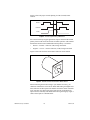
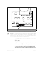
The FlexMotion-6C board will be damaged if the isolated voltage selection
jumpers on the board are set to use the internal voltage source and an external source is
connected directly to these signals on the nuDrive. Be careful to review the configuration
of the isolated voltage jumper section prior to powering any FlexMotion-6C circuits or the
host PC containing the FlexMotion-6C board.
Caution
I/O Terminal Blocks
The I/O connectors are configured differently on different nuDrives,
as described in the following sections.
CX and SX nuDrive Configuration
For CX and SX nuDrives, general-purpose digital I/O lines are provided to
augment the motion signals. The I/O lines are organized into two separate
I/O connectors, with each group using a separate six-position terminal
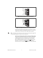
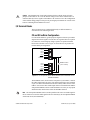
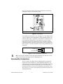
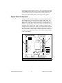
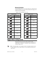
block with removable screws. Figure 11 shows the two six-position I/O
terminal block pin assignments.
I/O 1
I/O 2
I/O 3
I/O 4
Enable
Common
1
2
3
4
5
6
I/O 5
I/O 6
I/O 7
I/O 8
Enable
Common
1
2
3
4
5
6
ENABLE Switch
(ON = Closed)
Figure 11. Pin Assignments for the Two Six-Position I/O Terminal Blocks on the
CX and SX nuDrives
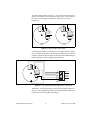
The ENABLE switch, located on the front panel of your nuDrive, controls
the enable signal input. The active-low enable signal input is also available
on pin 5 of each I/O terminal block and can remotely enable all axes in the
nuDrive. You can use either enable input on the I/O terminal blocks OR the
front panel ENABLE switch to enable the nuDrive accessory. E-stop inputs
and the host bus interlock also affect the ENABLE function.
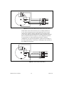
Note The front panel ENABLE switch is wired in parallel to the active-low enable signal of
the I/O connector. To use the enable signal in the I/O connector(s), the front panel ENABLE
switch must be off (not illuminated).
© National Instruments Corporation
13
nuDrive Accessory User Guide