1
Operating Instructions
Touchpoint Pro
MAN0923_Issue 3_04/15
Touchpoint Pro
Operating Instructions
Contents
Section
Page
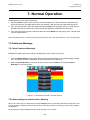
1
Safety and Information8
1.1 How to use this manual
11
1.2 Safety Hazards
12
1.3 Location and Description of Warning Labels
14
1.3.1 Safety Warning Labels
14
1.3.2 Equipment Rating Labels (Hazardous Locations)
15
1.4 Disposal
16
1.4.1 Touchpoint Pro System
16
1.4.2 Packaging
15
1.4.3 Batteries
17
1.5 Restriction of Hazardous Substances (RoHS) Directive
17
1.6 Waste Electrical and Electronic Equipment (WEEE) Directive
17
1.7 Information
18
2
Overview / Introduction19
2.1 Touchpoint Pro
19
2.2 Touchpoint Pro Controller
20
2.3 Remote Touchpoint Pro unit
20
2.4 System Topology
21
2.5 Communication/Power Rail and Ring Network
21
2.6 Input/Output (I/O) modules
22
2.6.1
Available Modules
23
2.7 System Interaction
23
2.8 Sensor Catalogue
24
2.9 Power Supply Options
25
2.9.1
Touchpoint Pro Power Supplies
25
2.9.2
Touchpoint Pro Power Redundancy Module
25
2.9.3
Touchpoint Pro UPS Module with Backup Battery
26
3
Mechanical Installation27
3.1 Siting considerations
27
3.2 Wall Mounted Enclosures
27
3.2.1
Small Wall Mounted Enclosure – Mild Steel
29
3.2.2
Medium Wall Mounted Enclosure – Mild Steel
29
3.2.3
Large Wall Mounted Enclosure – Mild Steel
30
3.3 Hazardous Area Enclosure
31
3.4 Floor Standing Enclosures
32
3.4.1 Floor Standing Cabinet - Front Access
33
3.4.2 Floor Standing Cabinet - Rear Access
35
3.5 19” Rack mounted unit
37
3.6 Panel Mount Controller
37
3.7 Touchpoint Pro Battery Box
39
3.7.1 Siting considerations
39
3.7.2 Installation and Assembly
39
3.7.2.1 Mounting the Touchpoint Pro Battery Box to a wall
39
3.7.3 Touchpoint Pro Battery Box Assembly
41
3.8 Cooling and Ventilation
43
4
Electrical Installation44
4.1 Power Consumption
44
4.2 Power Supply
44
4.2.1 AC Power Input
44
4.2.2 DC Power Input
45
4.2.3 DC Power Output
45
2
MAN0923_Issue 3_04/15
Touchpoint Pro
Operating Instructions
Contents
4.3 Cabling Requirements
4.3.1
Ring Network
4.3.2
Field devices
4.3.3
Power Supplies
4.3.4
Bus interfaces
4.3.5Ethernet
4.3.6 Touchpoint Pro Battery Box
4.4 Cabling Requirements – Additional info for assembly by system integrators
4.4.1
24 Vdc Power - Controller
4.4.2
Internal network connections
4.5 Ring Network Distance Restrictions
4.6 Earthing
4.7 EMC / RFI Considerations
4.8 Electrical Connections
4.8.1
Touchpoint Pro Power Supplies
4.8.1.1
120 W 24 Vdc Power Supply Unit
4.8.1.2
240 W 24 Vdc Power Supply Unit
4.8.1.3
480 W 24 Vdc Power Supply Unit
4.8.2
Power Redundancy Module
4.8.3
UPS and Battery Box
4.8.4
Analogue Input Module 4-20 mA
4.8.5
Analogue Input Module mV Bridge
4.8.6
Digital Input Module
4.8.7
Relay Output Module
4.8.8
Ring Coupling Module
4.8.9 System State Relays
4.8.10 Power Supply Unit Status Inputs
5
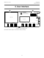
User Interface
5.1 General
5.2 Access Levels
5.3 User Interface Software
5.4 Local Interface (Touchscreen)
5.5 Web Server
5.6 PC Configuration Software
5.7 SD Card
5.8Interfaces
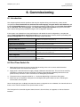
6
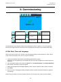
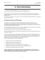
Commissioning
6.1Introduction
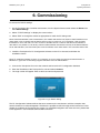
6.2 First Time Switch On
6.3 Set Date, Time and Language
6.4 Program Users and Passwords
6.5 Setup Web Server
6.5.1 TCP/IP Settings
6.5.2 Internet Explorer 8 Settings
6.5.3 Windows Settings
6.6 Setup PC Configuration Software (optional)
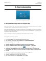
6.7 Verify Default Configuration and Program Tags
6.8 Commission Input / Output Modules
6.9 Channel Configuration
6.9.1 Introduction
6.9.2
Configuring a Channel
6.9.3
Editing a Configured Channel
6.9.4 Removing an I/O Module
3
45
46
46
46
46
46
46
47
47
47
47
48
50
51
51
51
52
53
54
55
57
60
61
62
64
66
66
68
68
68
71
72
72
73
73
73
75
75
75
76
77
78
78
79
79
79
81
82
83
83
84 85
85
MAN0923_Issue 3_04/15
Touchpoint Pro
Operating Instructions
Contents
6.10 Commission Power Supply Unit Status Channels
86
6.11 Redundant Control Centre Board Configuration
86
6.12 Buzzer Activation and Button Password Protection
87
6.13 Touch Panel Configuration
88
6.13.1 Calibrate touch panel
89
6.14 Service Contact Settings
88
6.15 Back up Configuration
88
6.16 Calibrate mV input channels
89
6.17 Calibrate mA input channel loops
90
7
Normal Operation92
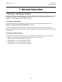
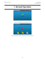
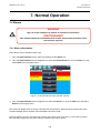
7.1 Safety Function
92
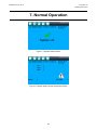
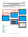
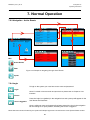
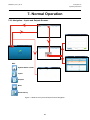
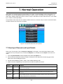
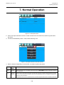
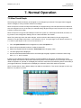
7.2 Overview - Touchscreen Interface
92
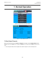
7.2.1
System Status screen
92
7.2.2
Navigation - Inputs and Outputs Screens
94
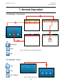
7.2.3
Navigation - Active Events
95
7.2.4Login
95
7.3 Overview – Web Server Interface
96
7.3.1
Start the Web Server
96
7.3.2
System Status Screen
96
7.3.3
Navigation – Inputs and Outputs Screens
98
7.3.4
Navigation – Active Events
99
7.3.5
Navigation – Extras
99
100
7.4 Alarms
7.4.1
View active alarms
100
7.4.2
Acknowledge an active alarm
101
7.4.3
Reset a latched alarm
101
7.5 Faults and Warnings
102
7.5.1
View Faults and Warnings
102
7.5.2
Acknowledge an active Fault or Warning
102
7.5.3
Reset a latched Fault or Warning
103
7.6Inhibit
103
7.7 View Input Channels and Input Details
104
7.8 View Output Channels
105
7.9 View Trend Graph
107
7.10 View Event History
108
7.11 Generate Reports
108
7.12 Access Diagnostic information
109
7.13 Check the capacity of the SD Card
109
7.14 Access Help
109
7.15 System State Relays
109
8
Maintenance
110
8.1 Testing the Touchpoint Pro System
110
8.1.1 Introduction
110
8.1.2 Field Inputs Test
111
8.1.3 Configuration Settings Test
112
8.1.4 Cause and Effect Test
113
8.2 Routine maintenance
114
8.3 Exercise the relays
114
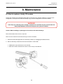
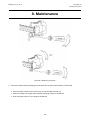
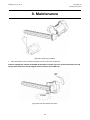
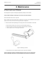
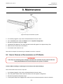
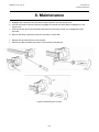
8.4 How to replace a faulty I/O module
115
8.5 How to add a new I/O Module
119
8.6 How to Remove or Decommission an I/O Module
120
8.7 Backup / Restore configuration
122
8.8 Change the SD Card
123
4
MAN0923_Issue 3_04/15
Touchpoint Pro
Operating Instructions
Contents
8.9 Calibrate mV input channels
123
8.10 Touchpoint Pro Battery Box
126
8.10.1 DC-UPS LED Indications
126
8.10.2 Routine maintenance
128
8.10.3 Changing a fuse
128
8.10.4 Replacement Batteries
128
Problem Solving129
9
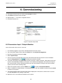
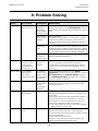
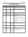
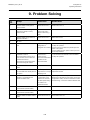
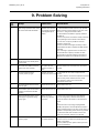
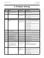
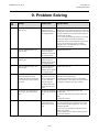
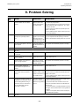
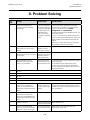
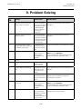
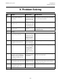
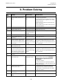
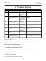
9.1Troubleshooting
129
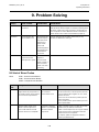
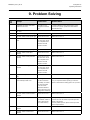
9.2 List of Error Codes
132
9.3 Further Assistance
143
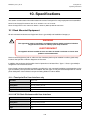
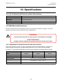
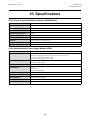
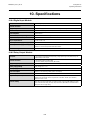
10 Specifications
144
10.1 Rack Mounted Equipment
144
10.1.1 Touchpoint Pro User Interface only
144
10.1.2 19” 5U Rack Enclosure with User Interface
144
10.1.3 19” 5U Remote Unit Enclosure without User Interface
145
10.2 Wall Mounted Enclosures
145
10.2.1 Common Specifications
145
10.2.2 Analogue Input Module mA
146
10.2.3 Analogue Input Module mV Bridge
146
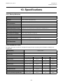
10.3 Floor Standing Enclosures
147
10.3.1 Floor Standing Cabinets Front Access
148
10.3.2 Floor Standing Cabinets Rear Access
148
10.4 Power Supplies and Fuses
148
10.4.1 Power Supply Units (OEM Specifications)
148
10.4.2 DIN Rail (Module Supply and Communication)
149
10.4.3 Ring Coupling Module (RCM)
149
10.4.4 Backplane
149
10.4.5 Power Supply Redundancy Module (RDN Module)
150
10.4.6 Uninterruptible Power Supply Module (UPS)
150
10.4.7 Backup Batteries
151
10.4.8 Cabinet DC Fuses
151
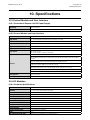
10.5 Control Module and User Interface
152
10.5.1 Controller & Remote Unit DC Input Supply
152
10.5.2 Control Module and User Interface
152
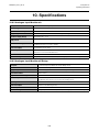
10.6 I/O Modules
152
10.6.1 Common Specifications
152
10.6.2 Analogue Input Module mA
153
10.6.3 Analogue Input Module mV Bridge
153
10.6.4 Digital Input Module
154
10.6.5 Relay Output Module
154
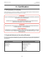
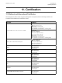
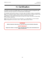
11 Certification
155
11.1 EC declaration of conformity
155
11.2 Applicable National and International Standards
155
11.3 National and International Certificates
156
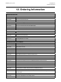
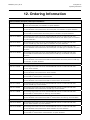
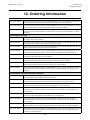
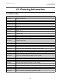
12 Ordering Information158
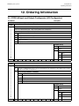
12.1 TPPR-M Input and Output Configurator (I/O Configurator)
158
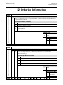
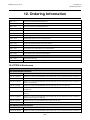
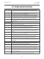
12.2 Touchpoint Pro Control System Part Number Generator
160
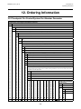
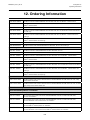
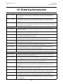
12.3 TPPR-V Controllers and Remote Units
161
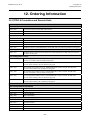
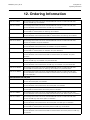
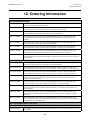
12.4 TPPR-H Enclosures
163
12.5 TPPR-W PSUs
175
13 Honeywell Analytics Product Warranty176
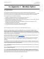
14 Appendix 1 - Modbus Option177
5
MAN0923_Issue 3_04/15
Touchpoint Pro
Operating Instructions
Contents
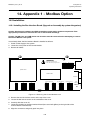
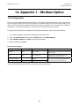
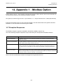
14.1Introduction
177
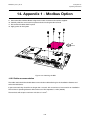
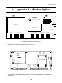
14.2 Installation
178
14.2.1 Installing the Bus Interface Board (Upgrade or OEM Assembly by
system integrators)
178
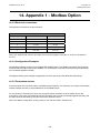
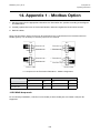
14.2.2 Cable recommendation
179
14.2.3 Electrical connections
180
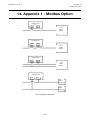
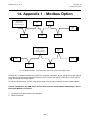
14.2.4 Configuration Examples
180
14.2.5 Termination resistor
180
14.2.6 Multi-drop mode
184
14.3 Configuration
185
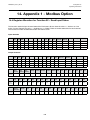
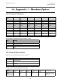
14.4 Register Allocation for Function 02 – Read Input Status
186
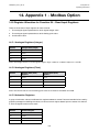
14.5 Register Allocation for Function 04 – Read Input Registers
187
14.5.1 Analogue Registers (Integer)
187
14.5.2 Analogue Registers (Float)
187
14.5.3 Animation Registers
187
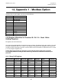
14.6 Register Allocation for Function 03 / 06 – Read / Write Holding Registers
188
14.6.1 Query Poll Registers
188
14.6.2 Query Types available
189
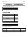
14.6.3 Command Poll Registers
190
14.6.4 Command Types Available
190
14.7 Exception Responses
191
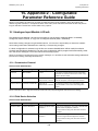
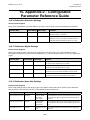
15 Appendix 2 - Configurable Parameter Reference Guide192
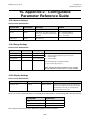
15.1 Analogue Input Module 4-20 mA
192
15.1.1 Commission Channel
192
15.1.2 Field Device Selection
192
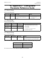
15.1.3 Sensor Settings
193
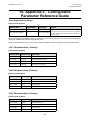
15.1.4 Range Settings
193
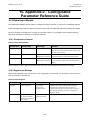
15.1.5 Display Settings
193
15.1.6 Suppression Settings
194
15.1.7 Threshold Alarm 1 Settings
194
15.1.8 Threshold Alarm 2 Settings
194
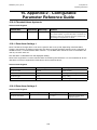
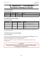
15.1.9 Threshold Alarm 3 Settings
194
15.1.10 Threshold Alarm Hysteresis
195
15.1.11 Short Term Exposure Limit (STEL) Alarm Settings
195
15.1.12 Long Term Exposure Limit (LTEL) Alarm Settings
195
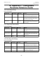
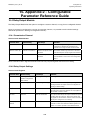
15.1.13 Rate Alarm Settings 1
196
15.1.14 Rate Alarm Settings 2
196
15.1.15 Inhibit Delay Settings
197
15.1.16 Signal Range Fault Settings
197
15.1.17 Gas Range Fault Settings
198
15.1.18 Calibration Reminder Settings
198
15.1.19 Calibration Signal Settings
199
15.1.20 Calibration Span Gas Settings
199
15.1.21 Inhibit Signalling Settings
199
15.1.22 Fault Signalling Settings 1
200
15.1.23 Fault Signalling Settings 2
200
15.1.24 Custom Fault “X” Detail Settings
200
15.2 Analogue Input Module mV Bridge
201
15.2.1 Commission Channel
201
15.2.2 Field Device Selection
201
15.2.3 Sensor Settings
202
15.2.4 Range Settings
202
6
MAN0923_Issue 3_04/15
Touchpoint Pro
Operating Instructions
Contents
15.2.5 Display Settings
202
15.2.6 Suppression Settings
203
15.2.7 Threshold Alarm 1 Settings
203
15.2.8 Threshold Alarm 2 Settings
203
15.2.9 Threshold Alarm 3 Settings
203
15.2.10 Threshold Alarm Hysteresis
204
15.2.11 Rate Alarm Settings 1
204
15.2.12 Rate Alarm Settings 2
204
15.2.13 Inhibit Delay Settings
205
15.2.14 Signal Range Fault Settings
205
15.2.15 Gas Range Fault Settings
205
15.2.16 Calibration Reminder Settings
206
15.2.17 Calibration Signal Settings
206
15.2.18 Calibration Span Gas Settings
206
15.3 Digital Input Module
207
15.3.1 Commission Channel
207
15.3.2 Digital Input Settings
207
15.3.3 Alarm Settings
208
15.3.4 Remote Interaction Settings
208
15.3.5 Remote Group Interaction Settings
208
15.4 Relay Output Module
209
15.4.1 Commission Channel
209
15.4.2 Relay Output Settings
209
15.4.3 Cause and Effect Type Selection
210
15.4.4 Input Channel Pre-selection for Cause and Effect Matrix
210
15.4.5 Cause & Effect Matrix
210
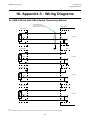
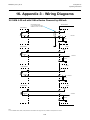
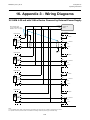
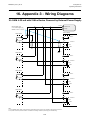
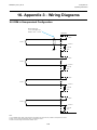
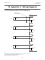
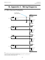
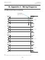
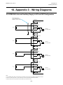
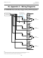
16 Appendix 3 - Wiring Diagrams211
16.1 AIM 4-20 mA with 3 Wire Device Powered by AIM mA
211
16.2 AIM 4-20 mA with 2 Wire Device Powered by AIM mA
212
16.3 AIM 4-20 mA with 3 Wire Device Powered by External Power Supply
213
16.4 AIM 4-20 mA with 2 Wire Device Powered by External Power Supply
214
16.5 DIM in Unsupervised Configuration
215
16.6 DIM in Supervised Open Circuit Configuration
216
16.7 DIM in Supervised Configuration
217
16.8 AIM mV with Sensor connectivity
218
16.9 ROM With Internal Auxiliary Supply in NC and NO Configuration
219
16.10 ROM With External Auxiliary Supply in NC and NO Configuration
220
17 Appendix 4 - Abbreviations221
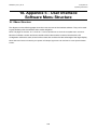
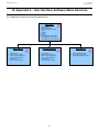
18 Appendix 5 - User Interface Software Menu Structure222
18.1 Menu Structure
222
18.1.1 Screen Navigation Sequence for Local HMI and Web Server
223
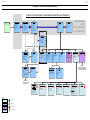
18.1.2 Sequence of System Configuration Screensfor Local Configuration
(and PC Configuration SW)
224
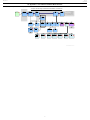
18.1.3 Navigation Sequence for PC Configuration SW-No Web
225
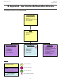
18.1.4 UI Calibration (Local HMI only)
226
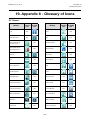
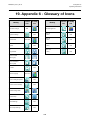
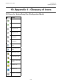
19 Appendix 6 - Glossary of Icons227
19.1 Icons for Touchscreen
227
19.2 Icons for Web Server and PC Configuration Software
229
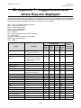
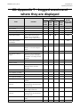
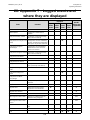
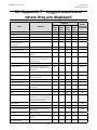
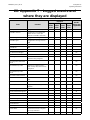
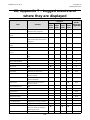
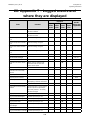
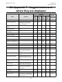
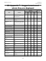
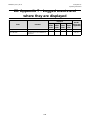
20 Appendix 7 - Logged events and where they are displayed230
7
MAN0923_Issue 3_04/15
Touchpoint Pro
Operating Instructions
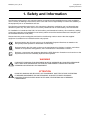
1. Safety and Information
The Equipment referred to in this manual contains components and assemblies that are each certified for
use in a variety of differing environments, and it is the site owner’s responsibility to confirm the suitability of
the equipment prior to its installation and use.
The Equipment assemblies referred to in this manual are collectively certified for use in a flammable gas
detection system only. Any other use is not currently certified and is not authorised by the manufacturer.
For installation in Canada and the USA, for both ordinary and hazardous locations, all connections, cabling,
overcurrent protection and installations must strictly adhere to both the National Electrical Code (NEC) and
the Canadian Electrical Code (CEC).
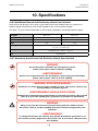
Please check the product rating plate and look for the following marks to ensure that the supplied
equipment is suitable for its intended location and purpose:
Products bearing the CE mark conform to all applicable European Directives as stated on the
Honeywell product specific EC Declaration of Conformity.
Products bearing the CSA mark conform to the requirements for Ordinary Locations, and where
marked on components and apparatus, Zone 2 and Division 2 Hazardous Locations.
Products, components and apparatus bearing the ATEX Explosion Protection mark conform to the
requirements for Zone 2 Potentially Explosive Atmospheres.
WARNING
FOR SAFETY REASONS THIS EQUIPMENT MUST BE OPERATED BY QUALIFIED PERSONNEL
ONLY. READ AND UNDERSTAND THE INSTRUCTION MANUAL COMPLETELY BEFORE
OPERATING OR SERVICING THE EQUIPMENT.
ATTENTION
POUR DES RAISONS DE SÉCURITÉ, CET ÉQUIPEMENT DOIT ÊTRE UTILISÉ, ENTRETENU
ET RÉPARÉ UNIQUEMENT PAR UN PERSONNEL QUALIFIÉ. ÉTUDIER LE MANUEL
D’INSTRUCTIONS EN ENTIER AVANT D’UTILISER, D’ENTRETENIR OU DE RÉPARER
L’ÉQUIPEMENT.
8
MAN0923_Issue 3_04/15
Touchpoint Pro
Operating Instructions
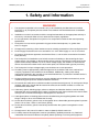
1. Safety and Information
WARNINGS
1. The equipment specified in this manual is only to be installed by the Manufacturer’s trained
personnel, or by competent persons trained in accordance with the Manufacturer’s installation
instructions.
2. Installation must be in accordance with the recognized standards of the appropriate authority in
the country concerned. Refer to local, national and company regulations.
3. Do not operate the Touchpoint Pro system or its components outside of their rated operating
specification.
4. Touchpoint Pro must not be operated in Oxygen enriched atmospheres, i.e. greater than
25% v/v Oxygen.
5. All equipment containing a User Interface must be suitably protected from direct sunlight and rain.
6. Power Supply Fluctuations are not to exceed DC 18 – 32 V SELV Supply or ±10 % of nominal.
7. All versions of Enclosure apparatus are electrical Class 1, and must be connected to Protective
Earth (Ground).
8.
The Touchpoint Pro installation must include a means of isolating or disconnecting the input
voltage supply. The isolation or disconnection device must be conveniently located close to the
system and be clearly labelled. For an AC mains voltage supply, the isolation or disconnection
device must disconnect both the line and neutral poles, but maintain earth (ground) continuity.
9. The Touchpoint Pro input voltage supply must include over-current protection.
10.
All cabling must be appropriately rated and approved in accordance with local, national and
company regulations, and suitable for the installation. Additionally, cabling must satisfy
requirements defined in the manuals of connected field devices, in particular if the field device is
certified for use in a hazardous location.
11. All signal cables and interconnections must be shielded and the shields terminated only at the
unified earth (ground) bus bar situated inside the enclosure
12. All conduits and cable armour shall be bonded to protective earth (ground). To avoid ground loops,
isolating cable entry glands shall be used at the enclosure end where conduits or armour are
earthed at the sensor end.
13. Cable entry glands, blanking plugs, reducers, adaptors and breather devices must be suitably
approved and must not reduce the IP rating or protection levels. Items should not be used if there
is a high risk of mechanical damage to the equipment or enclosure.
14. Cable gland plates or blanking plates must be installed using the supplied gaskets and metal
fixings. Failing to do so will invalidate the IP rating.
15. Access doors and entry points must not be opened when a flammable gas atmosphere is present.
(Class 1 Div.2, Class 1 Zone 2, and Zone 2 [ATEX])
16. Access doors and entry points must be kept closed when the system is energised in normal
operation.
17. All equipment in this manual is rated to +2000 m (6562 ft) altitude maximum.
18. For safety reasons this equipment must be operated by qualified personnel only. Read and
understand the Instruction Manual completely before operating or servicing the equipment.
9
MAN0923_Issue 3_04/15
Touchpoint Pro
Operating Instructions
1. Safety and Information
WARNINGS
19.
Touchpoint Pro systems may contain hazardous live terminals. Appropriate precautions should be
taken during operation, installation, and maintenance and servicing. Specifically, operators must
have appropriate training and experience to be aware of the hazards to which they may be
exposed, and of measures to minimise risk to themselves or other people.
20. The protection provided by the equipment may be impaired if the equipment is used in a manner
not specified or authorised by the manufacturer.
21.
Be aware that extended exposure of a detector element to certain concentrations of combustible
gases and air can introduce stress to the element that may seriously affect its performance, and
therefore recalibration should be carried out or the sensor replaced, or both, after an alarm due to
an indication of a high concentration.
22. When used in a Gas Detection summing up role, the gas reading may be higher than the actual
concentration at any one detector head location, or it may be the actual concentration at one
specific detector head.
Cautions
1. The USB Device port is for Maintenance use only. End users should use only the USB Host port with
a USB Flash drive adaptor, and backup / restore / upgrades should only be performed with the system
in Maintenance mode.
2. Touchpoint Pro power supply units, Ring Coupling Modules and Input / Output Modules have no user
serviceable parts. In the unlikely event of a failure, the power supply unit or module must be replaced
using only manufacturer supplied parts.
3. Do not use sharp objects to operate the touchscreen as this could irreparably damage the User Interface
and adversely affect its IP rating.
4. Use only soft, damp cloths or screen wipes to clean the Touchpoint Pro. Do not use solvents or
abrasives as they will damage the User Interface.
5. Once commissioned, Touchpoint Pro is intended for continuous operation.
10
MAN0923_Issue 3_04/15
Touchpoint Pro
Operating Instructions
1. Safety and Information
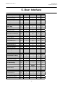
1.1 How to use this manual
The intention of this manual is that it is written in standalone sections so that the user can access only the
relevant information required at any time. It is strongly recommended that the index / bookmarks are used
for easy navigation.
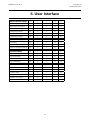
The manual is structured as follows:
Chapter
Title
Topic
1
Safety and Information
Safety, Regulatory Compliance and other important information
2
Overview
An overview of the Touchpoint Pro system and its components
3
Mechanical Installation
Instructions for mechanical installation of Touchpoint Pro units, as well as details for system
integrator customers of how to assemble a system
4
Electrical Installation
Instructions for electrical installation of Touchpoint Pro units, including power supply
calculation, cabling and earthing recommendations, and all wiring information
5
User Interface
A description of the Touchpoint Pro user interface, including menu structure and access
permissions
6
Commissioning
Instructions for first time switch on and configuration of the Touchpoint Pro system
7
Normal Operation
Instructions for normal day-to-day operation of the Touchpoint Pro system
8
Maintenance
Recommended maintenance operations, and details of how to carry out hardware and
firmware upgrades
9
Problem Solving
How to troubleshoot scenarios that may be encountered, and details of error codes and
suggested steps for resolution
10
Specifications
Specifications of all the component parts of Touchpoint Pro
11
Certification
Details of the regulatory approvals of Touchpoint Pro
12
Ordering Information
Part numbers for systems, components and accessories
13
Warranty Statement
Statement of warranty
14
Appendix – Modbus Option
How to install and operate the Modbus interface option
15
Appendix - Configurable
Parameter Reference Guide
Definitions, default values and available ranges of all I/O Module configurable parameters
16
Appendix - Wiring Diagrams Wiring diagrams for common sensor configurations
17
Appendix - Abbreviations
Definitions of abbreviations used in this document
18
Appendix - User Interface
Software Menu Structure
Diagrams showing the structure of the user interface software
19
Appendix - Icons
List of Touchpoint Pro icons and their meaning
20
Appendix - Events
List of Events that are logged by Touchpoint Pro and their meaning
11
MAN0923_Issue 3_04/15
Touchpoint Pro
Operating Instructions
1. Safety and Information
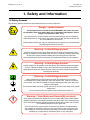
1.2Safety Hazards
The following specific hazards are associated with the use of this equipment:
Danger – Ignition Hazard
The Touchpoint Pro Controller is NOT ATEX/IECEx safe, and it may only
be installed in safe areas where there are no flammable atmospheres, and no
oxygen concentrations >25% v/v O2.
The Touchpoint Pro range includes a wall mounted enclosure that is certified as
ATEX/IECEx Zone 2, Class I Div 2 and Class I (Zone 2) safe, but this enclosure can
only be installed as a remote unit.
ATEX certified components may be used within the Touchpoint Pro, and these bear
the ATEX imprint shown to the left.
Warning – Lethal Voltage present
All power supplies must be hard wired and must include a circuit breaker (RCD /
RCCB), and (close by and unobstructed) a means of manually isolating and locking
out the power supply without breaking the true earth (ground) connection.
Removable plug and socket connection is not permitted under any circumstance.
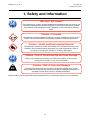
Warning – Lethal Voltage present
Lethal voltage may be present in this equipment when electrical power is applied.
There is a danger of death or injury from electrical shock. Isolate power before
opening electrical access panels. Ensure residual current is fully discharged before
touching live terminals.
Warning – Lethal Voltage present
Lethal voltage may be present both internally and externally to the system.
All installations, including cabinets, racks and remote units, must be connected
to true earth, and must be capable of staying earthed (grounded) when the power
supply is interrupted.
The Protective Earth (Ground) symbol is shown on the left, and it always has a green
background.
Do not confuse it with the chassis earth symbols shown below it.
Warning – Toxic Waste and Harmful By-products
Toxic waste and harmful by-products may accumulate within parts of the system.
Suitable respiratory, eye and skin protection should be worn when servicing these
items. Stringent industrial hygiene precautions should also be taken. Do not allow
non-essential personnel into the work area.
The Touchpoint Pro system and/or its sensors may become contaminated by
the ambient environment in which it or they are used. It is the Customer’s sole
responsibility to ensure that all appropriate safety precautions are taken before
handling any components or transferring them to any other party.
12
MAN0923_Issue 3_04/15
Touchpoint Pro
Operating Instructions
1. Safety and Information
Warning – Eye Hazard
The Touchpoint Pro system contains sealed lead-acid batteries that may pose an eye
hazard if the batteries have become damaged or pressurised. Always wear suitable
eye protection when handling the UPS or batteries, or when clearing up chemical
spills.
Caution – Corrosive
This equipment contains batteries containing corrosive substances that may pose a
health or environmental hazard if improperly handled or carelessly disposed of.
Caution – Health and Environmental Hazards
This equipment contains a number of potentially toxic substances that may pose
a health or environmental hazard if exposed to very high temperatures, VOCs or
corrosives, or if improperly handled or carelessly disposed of.
Caution – Risk of Permanent Eye and body Damage
Always wear suitable eye protection and PPE when installing or removing the
Touchpoint Pro system, or any of its components.
Caution – Risk of Injury and Damage
KG
Touchpoint Pro enclosures are heavy and may become unstable when moved.
Always wear PPE and ensure that mechanical means and sufficient personnel are
available to assist when moving or handling these items.
Please contact your Honeywell authorised representative if you need further advice on any of the above.
13
MAN0923_Issue 3_04/15
Touchpoint Pro
Operating Instructions
1. Safety and Information
1.3 Location and Description of Warning Labels
1.3.1 Safety Warning Labels
Warning labels are mounted in specified locations on the equipment. This is to indicate conditions under
which the user could be subjected to electrical hazards.
WARNING
WARNING
ISOLATE SUPPLIES BEFORE
SERVICING OR MAINTENANCE
HAZARDOUS LIVE CIRCUIT
AVERTISSEMENT
DANGEREUX CIRCUIT DIRECT
AVERTISSEMENT
ISOLER FOURITURES AVANT
DE PROCÉDER Á L’ENTRETIEN
OU LA MAINTENANCE
Figure 2 – Warning Label
Figure 1 – International Warning Label
Figure 3 – Protective Earth (Ground) Point
Figure 4 – Equipment Earth (Ground) Point
This Protective Earth (Ground) Location Point
label is used inside the system and is not normally
visible to the operator.
This Equipment Earth (Ground) Location Point
label is used inside the system and is not normally
visible to the operator.
14
MAN0923_Issue 3_04/15
Touchpoint Pro
Operating Instructions
1. Safety and Information
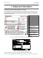
1.3.2 Equipment Rating Labels (Hazardous Locations)
The following labels are fixed in prominent positions on the enclosure and on relevant modules. It is the
user’s responsibility to check individual rating plates before installation and to ensure that specifications
are not exceeded during operation. Exceeding the approved ratings invalidates product certification and
the manufacturers’ warranties.
1
9
2
10
3
4
11
12
5
1.
Manufacturer
2.
Part Number
3.
Description
4.
ID and Serial Number
5.
Modification State
6.
Safety Warning
7.
Ingress Ratings
8.
Manufacturer Details
9.
Equipment Title
10. Limits for Voltage / Power / Ta
6
16
13
11.
CE Mark and Notified Body for
Production Supervision
14
12.
SIRA ATEX / IECEx Certificate
Numbers
13.
ATEX / IECEx Hazardous Area
Certification Details
14.
US/ Canadian Hazardous Location
and Zone Certification Details
7
15
6
Manufacturer’s Master Contract
15. Number and Canadian / US
Performance Identification
8
16.
CSA Monogram Canada and USA
Certified
Figure 5 - Example Remote Wall Mount (Zone 2 Div 2) Rating Label
Figure 6 - Touchpoint Pro AIM mA Rating Label
Note: Similar labels appear on AIM mV, DIM, RCM, ROM Modules and the Backplanes.
Note: The CE mark and Notified Body number 0518 shown on labels does not apply to Type ‘n’ approval.
15
MAN0923_Issue 3_04/15
Touchpoint Pro
Operating Instructions
1. Safety and Information
1.4Disposal
1.4.1 Touchpoint Pro System
The Touchpoint Pro system is constructed from the following materials:
Wall Mounted Enclosure
Powder coated mild steel
Zintec
19” Rack
Powder coated mild steel
I/O Modules
Casing – Polyamide PA 6.6 V0 (UL94), grey
Contents – printed circuit boards
Power Supply Units
Casing – Back case: Aluminum; Top case (with mesh): Steel with Nickel plating
Contents – printed circuit boards
Ring Coupling Module
Casing – Polyamide PA 6.6 V0 (UL94), green
Contents – printed circuit boards
1.4.2 Packaging
Touchpoint Pro outer packaging is made from cardboard. Facilities for recycling are widely available.
Touchpoint Pro inner packaging (used inside the Wall Mounted Enclosure) is made from Stratocell®, a Low
Density Polyethylene (LDPE) foam. The foam can be recycled and used as Stratocell® again where such
recycling facilities exist.
16
MAN0923_Issue 3_04/15
Touchpoint Pro
Operating Instructions
1. Safety and Information
1.4.3 Batteries
Below is a listing of batteries present in the products covered by this manual:
Battery Description
Battery Type
Location
Replaceable
12 V Rechargeable Battery
Valve Regulated Lead Acid
(VRLA) Sealed Battery
Battery backup unit for the
Power Supply (optional)
Yes
Batteries contain various active ingredients which store electrochemical energy and can be dangerous if
they contact your skin.
Removal and Disposal Information:
The symbol below means that according to local laws and regulations the battery installed within your
product should be disposed of separately from household waste. When the battery reaches its end of life,
take it to a collection point designated by local authorities.
1.5Restriction of Hazardous Substances (RoHS) Directive
Touchpoint Pro is compliant with the requirements of the RoHS Directive.
1.6Waste Electrical and Electronic Equipment (WEEE) Directive
This symbol indicates that this product and/or parts of the product may not be treated as
household or municipal waste. Waste electrical products (end of life) should be recovered/
recycled where suitable specialist WEEE disposal facilities exist. For more information about
recycling of this product, contact your local authority, our agent/distributor or the manufacturer.
17
MAN0923_Issue 3_04/15
Touchpoint Pro
Operating Instructions
1. Safety and Information
1.7Information
This manual is for use with the Touchpoint Pro.
The reader of this Operating Manual should ensure that it is appropriate in all details for the exact
equipment to be installed and/or operated. If in doubt, contact Honeywell Analytics for advice.
The following types of notices are used throughout this Operating Manual:
WARNINGS
Identifies a hazardous or unsafe practice which could result in severe injury or death to personnel.
Caution: Identifies a hazardous or unsafe practice which could result in minor injury to personnel, or
product or property damage.
Note: Identifies useful/additional information.
Disclaimer
Every effort has been made to ensure the accuracy of this document; however, Life Safety Distribution AG
can assume no responsibility for any errors or omissions in this document or their consequences.
Life Safety Distribution AG would greatly appreciate being informed of any errors or omissions that may be
found in the content of this document.
For information not covered in this document, or if there is a requirement to send comments/corrections
about this document, please contact Life Safety Distribution AG using the contact details given on the
last page.
Life Safety Distribution AG reserve the right to change or revise the information supplied in this document
without notice and without obligation to notify any person or organization of such revision or change.
If information is required that does not appear in this document, contact the local distributor/agent or Life
Safety Distribution AG
18
MAN0923_Issue 3_04/15
Touchpoint Pro
Operating Instructions
2. Overview / Introduction
2.1Touchpoint Pro
Touchpoint Pro is a control system for Honeywell Analytics’ (and third party) range of sensors, which
provides alarm evaluation and logically connectable relay outputs for alarm annunciation or control
equipment operation.
Any system can be built from just four main building blocks:
1. A control module with colour LCD touch screen User Interface
2. Plug-in Input / Output (I/O) modules
3. A backplane power and communications highway
4. Power Supplies
These basic components can be mounted in cabinets or racks (or a combination) and the I/O modules
freely mixed and matched in any combination. From small-scale systems to large fully integrated gas, fire
and shutdown systems, Touchpoint Pro has the flexibility to meet all your gas and fire safety system control
requirements.
The heart of Touchpoint Pro is the Controller, which includes the User Interface. The User Interface features
a full colour liquid crystal display (LCD) with touch screen, and provides engineers with an intuitive solution
to system set-up and deployment.
Touchpoint Pro System Key Components
1
Remote Unit
Remote Unit
Controller with User Interface
2
Input and Output Modules
mV and mA
Analogue
Input Modules
Relay Output
Module
3
4
Communication / Power Rail
Power Supply Units
Digital Input
Module
120W 24 Vdc
PSU
Figure 2.1 Touchpoint Pro system overview
19
240W 24 Vdc
PSU
Redundancy
Module
480W 24 Vdc
PSU
UPS
Module
MAN0923_Issue 3_04/15
Touchpoint Pro
Operating Instructions
2. Overview / Introduction
2.2Touchpoint Pro Controller
Each Touchpoint Pro system has one Controller, which forms the heart of the system. It contains the Control
Module and the User Interface, and handles the communication for the system.
The Touchpoint Pro Controller can be housed in any of the standard Touchpoint Pro Enclosures or in a
19” rack, where I/O modules, power supplies and the Communication / Power Rail can be included. The
Controller can also be supplied as a front panel for mounting into a custom system.
Within the Controller, the Control Module contains two major components – the Control Centre Board
and the Communication Board. The Control Centre Board (CCB) deals with all functions related to system
operation, as well as the LED indicators and buttons on the front panel, and the master system state relays.
An optional redundant CCB is available. The Communication Board (COB) handles the rest of the user
interfaces – touchscreen, bus output and other external interfaces such as the USB and Ethernet ports.
The Communication Board is completely independent from the Safety Function of the system.
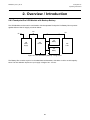
2.3Remote Touchpoint Pro unit
Each Touchpoint Pro system can contain multiple Remote Touchpoint Pro units. The Remote units contain
only I/O modules and the Communication / Power Rail, plus power supplies if desired.
Remote units can be located up to 1 km (cable length) from the Touchpoint Pro Controller, with a maximum
round trip of 3 km (cable length) for the complete system. The only connection required between the
Controller and Remote units is the network cable.
The Remote Touchpoint Pro unit can be housed in any of the standard Touchpoint Pro Enclosures, a 19” rack, or
a suitable third party enclosure.
Touchpoint Pro Controller
Remote Touchpoint Pro Unit
Max 1km
Max 3 km
Remote Touchpoint Pro Unit
Remote Touchpoint Pro Unit
Example:
Distances between units
0.5 km + 0.3 km + 1 km +
0.7 km + 0.4 km
Total round trip
2.9 km
Remote Touchpoint Pro Unit
Fig 2.2 Max allowed cable distances
20
MAN0923_Issue 3_04/15
Touchpoint Pro
Operating Instructions
2. Overview / Introduction
2.4System Topology
Touchpoint Pro can be implemented using a centralised or distributed cabling architecture. With a centralised
architecture, all field devices are cabled back to a central point (so-called “home run”). In a distributed
architecture, field devices are clustered with short cable runs to a control unit (in this case the Touchpoint Pro
Remote unit) and a minimal amount of cabling is required back to the central point (in this case only the Ring
Network cable). The only restrictions on a distributed architecture are the maximum round trip distance of 3
km and the maximum distance between two Touchpoint Pro units (Controller or Remote) of 1 km.
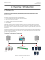
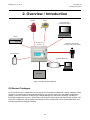
2.5 Communication / Power Rail and Ring Network
The Touchpoint Pro Communication / Power Rail directly provides power and network connection to the I/O
modules, minimising the wiring required. There is a single connection for the 24 Vdc supply, which is then
distributed to the I/O modules. The network cables connect to the Ring Coupling Module, which handles
the communication between the modules and the Control Centre Board. The Communication / Power Rail
is available in three lengths suitable for 5, 7, 9 or 10 I/O modules. The choice of length may be restricted by
the size of the selected power supply option.
Touchpoint Pro Controller
PSU
RCM
Input Modules
Output Modules
DIN Rail
Communication Control Centre
Board (COB)
Board (CCB)
Ring B
Ring A
Redundant Ring Network
Gas Detectors
Actuator Field Devices
Fig 2.3 Touchpoint Pro Controller
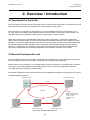
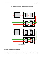
The Ring Network is the communication link between all I/O modules in a Touchpoint Pro system and
the Control Centre Board. The Ring Network is the only connection required between a Touchpoint Pro
Controller (containing the Control Module and User Interface) and Remote Touchpoint Pro units.
The Ring Network is implemented for redundancy as two loops transmitting in opposite directions (Ring A
and Ring B). The network is self-healing since each module only communicates with the one next to it. If
a module fails, the modules after it continue to transmit data in the direction away from the failed module,
while the ones before it transmit in the other direction. Thus the Touchpoint Pro system can immediately
detect and locate a failed module, without affecting the availability of the rest of the system. For a single
Touchpoint Pro Controller, the Ring Network runs between the Communication / Power Rail and the Control
Module. For a system with a Touchpoint Pro Controller and Remote units, the network runs additionally over
data cable between all the units in a system.
Note: The Touchpoint Pro Ring Network does not accommodate spurs.
21
MAN0923_Issue 3_04/15
Touchpoint Pro
Operating Instructions
2. Overview / Introduction
Ring Network
I/O Module 2
I/O Module 1
Touchpoint Pro Controller
I/O Module 3
I/O Module 4
Self-healing Ring Network with Failure at Module 2
I/O Module 2
I/O Module 1
Touchpoint Pro Controller
I/O Module 3
I/O Module 4
Fig 2.4 Ring Network
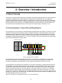
2.6Input / Output (I/O) modules
Various types of I/O modules are available, each containing four channels. A single Touchpoint Pro system
can contain up to 64 input channels (16 input modules) and 128 output channels (32 output modules).
22
MAN0923_Issue 3_04/15
Touchpoint Pro
Operating Instructions
2. Overview / Introduction
2.6.1 Available Modules
Analogue Input Module 4–20 mA (AIM mA)
4-channel Analogue Input Module for 2 or 3 wire 4-20mA detector
signals
Analogue Input Module mV Bridge (AIM mV)
4-channel Analogue Input Module for mV-Bridge signals; powers up to 4
catalytic flammable gas detectors
Digital Input Module (DIM)
4-channel Digital Input Module for switched input devices such as
manually operated push buttons. Can also be used for remote alarm
acknowledge, reset and output inhibit
Relay Output Module (ROM)
4-channel Relay Output Module incorporating 4 SPCO relays; suitable to
activate field mounted annunciators
Note: Communication/Power Rails may be included in the system without any I/O Modules, however there is
a limit of 5 such Communication/Power Rails within the full 3 km loop of the system.
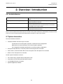
2.7System Interaction
The User Interface consists of:
• Interface software with three ways to access:
Touchscreen for normal system operation, maintenance and configuration
Web Server for remote access to view normal system operation
PC Configuration Software (optional) for convenient system configuration
• Accept and reset buttons on the front panel of the Touchpoint Pro Controller
• Power, Alarm, Fault and Inhibit LEDs on the front panel of the Touchpoint Pro Controller
• Buzzer on the Touchpoint Pro Controller
Further System Interfaces consist of:
• Two master relays, System Failure and System Fault
• Connections for SD Card and USB memory device
• 10/100 Mbps Ethernet connection
• Optional digital bus interface
23
MAN0923_Issue 3_04/15
Touchpoint Pro
Operating Instructions
2. Overview / Introduction
Actuators
Sensors
Laptop Configuration
(PC Configuration Software)
Gateway
Touchpoint Pro
Controller
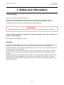
Configuration and Visualisation
(Touchscreen, LEDs, Sounder, Buttons)
Removable Memory
Visualisation (Web Server)
Master Relays
Fig 2.5 Touchpoint Pro Interfaces
2.8 Sensor Catalogue
For convenient sensor configuration, the Touchpoint Pro Controller is loaded with a sensor catalogue, which
contains a complete listing of all Honeywell Analytics’ gas sensors, each with a full default configuration
setting. A user can choose to configure input channel settings from the sensor catalogue, resulting in a
three step configuration process – select channel ID, program channel tags and select sensor and gas. The
rest of the configuration will be loaded automatically. The full configuration can be viewed afterwards, and
individual parameters changed if desired.
24
MAN0923_Issue 3_04/15
Touchpoint Pro
Operating Instructions
2. Overview / Introduction
2.9 Power Supply Options
2.9.1 Touchpoint Pro Power Supplies
The Touchpoint Pro System can be equipped with power supplies of different capacity. The power supplies
are mounted to the DIN-Rail and are available in the following ratings:
120 W (5 A at 24 Vdc)
240 W (10 A at 24 Vdc)
480 W (20 A at 24 Vdc)
The power supplies have status outputs which can be connected to dedicated inputs on the Touchpoint Pro
Controller to give a signal if there is a failure of an individual power supply unit.
2.9.2 Touchpoint Pro Power Redundancy Module (RDN)
The Redundancy Module controls two input DC power supplies, maximum 20 A each. If one supply fails,
the Redundancy Module will switch over to the other supply, maintaining the DC output. Alarm relays are
provided which will open if one of the input supplies fails.
PSU
PSU
Redundancy
Module
Vout
Load
max 20A
Figure 2.6 Power redundancy configuration
25
MAN0923_Issue 3_04/15
Touchpoint Pro
Operating Instructions
2. Overview / Introduction
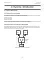
2.9.3 Touchpoint Pro UPS Module with Backup Battery
The UPS Module can be used in combination with the separate Touchpoint Pro Battery Box to protect
against failure of the AC supply, as shown below:
DC
AC
24V
Power
Supply
DC
12V
Battery
24V
DC-UPS
24V
Load
12V
Battery
Figure 2.7 UPS and Battery Backup configuration
The Battery Box contains a pair of 12 V sealed lead acid batteries, with either 12 Ah or 27 Ah capacity.
Note: The UPS Module requires an input supply voltage of 26 - 32 Vdc.
26
MAN0923_Issue 3_04/15
Touchpoint Pro
Operating Instructions
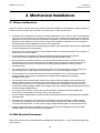
3. Mechanical Installation
3.1 Siting considerations
There is a range of wall floor and rack mounted enclosures available for Touchpoint Pro. When choosing a
location for the Touchpoint Pro (Controller or Remote type), consider the following:
•
Touchpoint Pro is specified for operation in ambient temperatures from -40°C to +65°C (I/O Modules) or
-20°C to +55°C (Touchpoint Pro Controller). However the upper ambient temperature may be reduced
dependant on the type and quantity of installed components. It is the user’s responsibility to check the
equipment rating plates for the true ambient range of the installation. Operation of the unit outside of
this temperature range invalidates the warranty and certification.
• All enclosures and racks have individual Ingress Protection and type ratings. It is the user’s responsibility
to check rating plates for requirements.
• Only Zone 2 Div 2 and remote units can be installed outside in unprotected locations. See ‘Chapter 10
Specifications’ for further details.
• The Touchpoint Pro enclosures should be protected from direct sunlight where exposure could cause the unit temperature to rise beyond the specified operating limits.
•
Ensure that there is sufficient clearance to mount the wall mounted enclosure, and open the door.
A clearance of 100 mm all round plus space for cable entries is required. The door hinge is on the
left side. Beware of proximity to entries, exits and sloping ceilings. Beware of siting in vehicle
movement areas.
• For a Touchpoint Pro Controller, ensure that the screen can be viewed easily and touch screen can
be reached. A touch screen height of approximately 1.5 m is recommended for comfort.
• The Touchpoint Pro wall mounted enclosure should be installed only on a vertical surface avoiding sloping surfaces. Only use the mounting fixtures supplied with the apparatus, and follow installation instructions.
•
The mounting surface should be flat, and strong enough to bear the weight of the Touchpoint Pro system. Solid brick type construction is recommended. Drywall / plasterboard, dry lined or timber
framed type construction is not considered to be a suitable structural material. Take account of the
contents and external cabling in addition to the weight of the wall mounted enclosure itself (check maximum
enclosure weights detailed below). • If more than one enclosure is to be used, ensure that there is sufficient clearance between the enclosures for cable glands, mounting, cooling, door opening etc.
• It is the installer’s responsibility to ensure that the unit temperature does not rise beyond the specified
operating limits.
• Touchpoint Pro conforms to the requirements of European and other standards for EMC and RFI. It should not be installed in close proximity to the antennae of high power radio, radar and satellite communication equipment, or in the vicinity of high voltage switching gear or overhead power lines.
• All signal cables should be protected from stray or induced current, especially if you are re-using
existing cables with a new Touchpoint Pro installation.
3.2Wall Mounted Enclosures
There are a range of wall mounted enclosures available for Touchpoint Pro - small, medium and large mild
steel versions.
27
MAN0923_Issue 3_04/15
Touchpoint Pro
Operating Instructions
3. Mechanical Installation
Correct
Incorrect
Figure 3.1 Touchpoint Pro wall mounting brackets orientation
Caution: The Touchpoint Pro enclosure is heavy (refer to table of typical weights, single person lift is
not recommended). Before lifting the enclosure, consider and implement control measures to reduce
the risk of injury. Refer to local safety regulations.
Caution: The Touchpoint Pro wall mounting brackets must always be installed in a vertical orientation
as shown.
Fixing bolts should be of minimum diameter 8 mm, to a depth of minimum 50 mm.
Caution: It is the installer’s responsibility to select the appropriate fixings taking into account the
structure of the mounting surface and the weight of the enclosure.
The typical weights of the wall mounted enclosures are shown in the table below. Please be aware that the
weight may vary depending on the options selected.
Description
Approximate
Weight in kg
600 x 600 x 300 WM steel enclosure Local
37
600 x 600 x 300 WM steel enclosure Remote
37
800 x 600 x 300 WM steel enclosure Local
46
800 x 600 x 300 WM steel enclosure Remote
46
1200 x 800 x 300 WM steel enclosure
81
28
MAN0923_Issue 3_04/15
Touchpoint Pro
Operating Instructions
3. Mechanical Installation
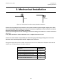
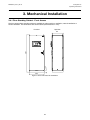
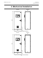
3.2.1 Small Wall Mounted Enclosure – Mild Steel
The dimensions of the small wall mounted unit (Controller or Remote) are shown below (all dimensions in
mm):
R4,5 TYP
600
645
681
R7,5 TYP
560
600
300
387
Figure 3.2 Touchpoint Pro Small Wall Mounted Enclosure - Mild Steel
3.2.2 Medium Wall Mounted Enclosure – Mild Steel
881
845
800
The dimensions of the medium wall mounted unit (Controller or Remote) are shown below (all dimensions in
mm):
R4,5 TYP
R7,5 TYP
560
600
300
388
Figure 3.3 Touchpoint Pro Medium Wall Mounted Enclosure - Mild Steel
29
MAN0923_Issue 3_04/15
Touchpoint Pro
Operating Instructions
3. Mechanical Installation
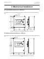
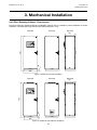
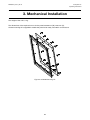
3.2.3 Large Wall Mounted Enclosure - Mild Steel
The dimensions of the large wall mounted unit (Controller or Remote) are shown below (all dimensions in
mm):
Figure 3.4 Touchpoint Pro Large Wall Mounted Enclosure - Mild Steel
30
MAN0923_Issue 3_04/15
Touchpoint Pro
Operating Instructions
3. Mechanical Installation
3.3 Hazardous Area Enclosure
Caution: The Touchpoint Pro enclosure is heavy (refer to table of typical weights, single person lift is
not recommended). Before lifting the enclosure, consider and implement control measures to reduce
the risk of injury. Refer to local safety regulations.
The Touchpoint Pro range includes a wall mounted enclosure which is certified for use in hazardous areas/
locations (ATEX/IECEx Zone 2, Class I Div 2, and Class I (Zone 2)). This enclosure can only be used as a
remote unit, no controller option is available.
510
580
780
325
Ø11
560
590
Figure 3.5 Touchpoint Pro Hazardous Area Enclosure
Fixing bolts should be of minimum diameter 8 mm, to a depth of minimum 50 mm.
Caution: It is the installer’s responsibility to select the appropriate fixings taking into account the
structure of the mounting surface and the weight of the enclosure.
The typical weight of the hazardous area enclosure is shown in the table below. Please be aware that the
weight may vary depending on the options selected.
Description
Approximate Weight in kg
Hazardous Area Enclosure
42
31
MAN0923_Issue 3_04/15
Touchpoint Pro
Operating Instructions
3. Mechanical Installation
3.4 Floor Standing Enclosures
Caution: The Touchpoint Pro enclosure is heavy (refer to table of typical weights). Before lifting the
enclosure, consider and implement control measures to reduce the risk of injury. Refer to local safety
regulations.
Caution: To prevent the floor standing enclosure toppling over, it must be mechanically secured in
place, either bolted through the plinth to the floor, or bolted to a suitable wall structure.
Caution: Do not block any vents if fitted
The typical weights of the floor standing enclosures are shown in the table below. Please be aware that the
weight may vary depending on the options selected.
Description
Approximate
Weight in kg
FS cabinet 2000 x 800 x 600 Front Access No ventilation
201
FS cabinet 2000 x 800 x 600 Front Access Natural ventilation
201
FS cabinet 2000 x 800 x 600 Front Access Forced ventilation
201
FS cabinet 2000 x 800 x 600 Rear Access No ventilation
201
FS cabinet 2000 x 800 x 600 Rear Access Natural ventilation
201
FS cabinet 2000 x 800 x 600 Rear Access Forced ventilation
201
32
MAN0923_Issue 3_04/15
Touchpoint Pro
Operating Instructions
3. Mechanical Installation
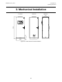
3.4.1 Floor Standing Cabinet - Front Access
The front access floor standing cabinet is available in options with no ventilation, natural ventilation or
forced ventilation. The dimensions are shown below (all dimensions in mm):
Front View
Right View
100
2121
611
PLINTH
802
Figure 3.6 Front Access No Ventilation
33
MAN0923_Issue 3_04/15
Touchpoint Pro
Operating Instructions
3. Mechanical Installation
Right View
611
100
2143
Front View
PLINTH
802
Figure 3.7 Front Access Natural Ventilation
Right View
611
100
2143
Front View
PLINTH
802
Figure 3.8 Front Access Forced Ventilation
34
MAN0923_Issue 3_04/15
Touchpoint Pro
Operating Instructions
3. Mechanical Installation
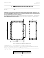
3.4.2 Floor Standing Cabinet - Rear Access
The rear access floor standing cabinet is available in options with no ventilation, natural ventilation or forced
ventilation. The dimensions are shown below (all dimensions in mm):
Rear View
Right View
611
100
2121
Front View
PLINTH
PLINTH
802
Figure 3.9 Rear Access No Ventilation
Rear View
100
2143
Front View
PLINTH
PLINTH
802
Figure 3.10 Rear Access Natural Ventilation
35
Right View
611
MAN0923_Issue 3_04/15
Touchpoint Pro
Operating Instructions
3. Mechanical Installation
Rear View
100
2143
Front View
PLINTH
PLINTH
802
Figure 3.11 Rear Access Forced Ventilation
36
Right View
611
MAN0923_Issue 3_04/15
Touchpoint Pro
Operating Instructions
3. Mechanical Installation
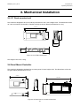
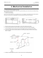
3.5 19” Rack mounted unit
This module is designed to fit into an industry standard 19” rack, with a height of 5U. The dimensions of the
19” rack mounted unit (Controller or Remote version) are shown below (all dimensions in mm):
483 mm
222 mm
145 mm
462.1 mm
110 mm
110 mm
85,5 mm
135 mm
Figure 3.12 19” Rack dimensions
The weight of the unit is 10 kg.
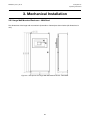
3.6Panel Mount Controller
This module is designed to be fitted into a custom panel. It has a height of 5U. The dimensions of the unit
are given below (all dimensions in mm):
358 mm
144.3 mm
222 mm
332.7 mm
67 mm
78 mm
Figure 3.13 Panel mount controller dimensions
37
MAN0923_Issue 3_04/15
Touchpoint Pro
Operating Instructions
3. Mechanical Installation
The weight of the unit is 1 kg.
The dimensions of the required cut out for the panel are 368 mm (W) x 232 mm (H).
A bezel mounting kit is supplied to enable the panel to be neatly mounted in an enclosure.
Figure 3.14 Bezel Mounting Kit
38
MAN0923_Issue 3_04/15
Touchpoint Pro
Operating Instructions
3. Mechanical Installation
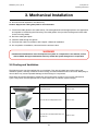
3.7 Touchpoint Pro Battery Box
Note: the following safety symbols are used on or within the Touchpoint Pro Battery Box:
Keep away from
Children
No naked Flames
Warning
Warning
Electric Shock
Read Instructions
Wear Eye Protection
3.7.1 Siting considerations
When choosing a location for the Touchpoint Pro Battery Box, consider the following:
• The Touchpoint Pro Battery Box is specified for operation in ambient temperatures from -20°C to +45°C.
Operation of the unit outside of this temperature range invalidates the warranty and certification.
• The Touchpoint Pro Battery Box must be installed in a Pollution Degree 2 environment as defined by IEC 61010-1 (CSA-C22.2 No 61010, ANSI/ISA 61010-1(82.02.01)), i.e. an environment such as an office or
control room.
• The Touchpoint Pro Battery Box is designed for permanent connection to the Touchpoint Pro System
UPS for continuous operation. The maximum cable length between the Touchpoint Pro Battery Box and
the Touchpoint Pro System UPS is 5 m. Wire size must be 4 mm2.
• The Touchpoint Pro Battery Box should be installed only on a vertical surface avoiding sloping surfaces.
Only use the mounting brackets supplied with the apparatus, and follow installation instructions.
•
The mounting surface should be flat, and strong enough to bear the weight of the Touchpoint Pro system. Drywall / plasterboard, dry lined or timber framed type construction is not considered to be a
suitable structural material, unless strengthened with additional supports or braces and/or special fixings. Take account of the contents and external cabling in addition to the weight of the unit itself.
• The Touchpoint Pro Battery Box should have a clearance of 200 mm to either side, and there should be no heat sources below or adjacent to the unit.
• Ensure access to disconnecting device (switch inside the enclosure)
3.7.2 Installation and Assembly
Due to regulations on shipping batteries, which are classified as hazardous goods, it is not possible to
ship the Touchpoint Pro Battery Box as a complete assembly. It is necessary to fit the batteries into the
enclosure, and fit the connecting cables supplied. For safety reasons, it is recommended that the 17 Kg
batteries are installed after mounting the housing on the wall.
Caution: The batteries within the Touchpoint Pro Battery Box have a limited storage life. Please
ensure that the Battery Box is connected and charged within 3 months of delivery.
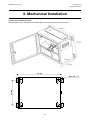
3.7.2.1 Mounting the Touchpoint Pro Battery Box to a wall
Caution: The assembled Touchpoint Pro Battery Box is heavy (>25 kg or >15 kg, single person lift is
not recommended). Before lifting the enclosure, consider and implement control measures to reduce
the risk of injury. Refer to local safety regulations.
39
MAN0923_Issue 3_04/15
Touchpoint Pro
Operating Instructions
3. Mechanical Installation
Caution: Do not block the vents
The dimensions of the Touchpoint Pro Battery Box and mounting points are shown below.
40
MAN0923_Issue 3_04/15
Touchpoint Pro
Operating Instructions
3. Mechanical Installation
1. Insert mounting brackets into mounting points. Tighten the M6 bolts to a torque of 6 Nm.
2. Select a suitable mounting position, taking into account the siting considerations above.
3. Mark and drill four holes corresponding to the mounting hole positions.
4. Secure the Battery Box enclosure in place. The mounting holes are 10 mm in diameter. Fixing bolts
should be minimum diameter 8 mm, to a depth of minimum 50 mm.
Caution: It is the installer’s responsibility to select the appropriate fixings taking into account the
structure of the mounting surface and the weight of the enclosure.
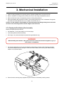
3.7.3 Touchpoint Pro Battery Box Assembly
Identify all required parts as follows:
• Two batteries - 12 Ah size (small) or 27 Ah size (large)
• Connecting cable and fuse assembly
• Kit of lugs, nuts, bolts and washers (used with large batteries only)
WARNING
When handling the batteries, take great care not to connect the terminals together, e.g. by a
tool such as a screwdriver.
1. For the large batteries only, fit a lug (supplied) to each battery terminal using the fixings supplied.
The correct sequence for the fixings is – bolt, flat washer, battery terminal, lug, flat washer, spring
washer, nut, as shown below:
2. Ensure that the securing strap supplied is open and clear of the battery seating surface
41
MAN0923_Issue 3_04/15
Touchpoint Pro
Operating Instructions
3. Mechanical Installation
3. Insert the first battery and slide to the right.
Note: The battery mounting plate is offset. Fit the right hand battery first to avoid the second battery being
restricted by the enclosure.
4. Insert the second battery.
Note: Ensure that the batteries are orientated as shown in the diagram, large batteries with the terminals at
the centre of the enclosure, small batteries with the terminals at the front of the enclosure.
5. Place the securing strap around the batteries, connect the buckle and pull it tight.
6. Connect the Red wire from the box terminal to the positive terminal of the left hand battery.
7. Connect the Black wire from the box terminal to the negative terminal of the right hand battery.
8. Connect the cable and fuse assembly between the remaining two battery terminals, red to positive,
black to negative.
9. Identify the required cable entry points. Unscrew and remove the cable gland plate.
42
MAN0923_Issue 3_04/15
Touchpoint Pro
Operating Instructions
3. Mechanical Installation
10.Drill out the hole required for the cable entry.
Caution: Support the cable gland plate to avoid distortion.
11.Fit and lock cable glands to the cable entries. The cable glands should be appropriate to the application
and capable of maintaining the IP20 rating. The cable glands must provide anchorage and stress relief
for the incoming cables .
12.Re-fit the cable gland plate .
13.Feed the cable through the glands.
14.Terminate the cable in accordance with Chapter 4 Electrical Installation.
15.On completion of installation, close and lock the enclosure door.
WARNING
Unauthorised modification of the Touchpoint Pro system or components is not allowed, as this
will invalidate the legal certifications and may render the system dangerous or inoperable.
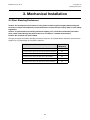
3.8 Cooling and Ventilation
The following items may be supplied with your purchase. They are an integral part of the cooling and
ventilation system, and they contribute to the IP rating, and should therefore not be removed. Attempting to
remove them may cause irreparable damage to the housings or components.
These items should be checked for cleanliness, dust and function as part of your normal maintenance
cycle. Faulty items must be replaced with an exact match item to maintain system integrity.
Description
Part Number
Roof Exhaust Unit
TPPR-V-1996
Door Inlet Vent and Replaceable Filter
TPPR-V-1997
Door Inlet Fan and Replaceable Filter 24V
DC Filter Fan
TPPR-V-1999
43
MAN0923_Issue 3_04/15
Touchpoint Pro
Operating Instructions
4. Electrical Installation
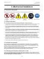
WARNING
Installation must be in accordance with the recognized standards of the appropriate authority
in the country concerned. Refer to local, national and company regulations.
4.1Power Consumption
The power consumption of your system was calculated when it was ordered. Please refer to the Certificate
of Conformity supplied, or the rating plate for the power consumption.
4.2 Power Supply
WARNING
All power supplies must be hard wired and must include a circuit breaker (RCD / RCCB), and
(close by and unobstructed) a means of manually isolating and locking out the power supply
without breaking the true earth (ground) connection.
Removable plug and socket connection is not permitted under any circumstance.
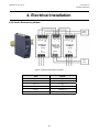
4.2.1 AC Power Input
AC Power input (if used) must be single phase, 100 -- 240 Vac, 50/60 Hz.
The mains supply requires an overcurrent protection rated in accordance with the rating plate on the
specific system. The supply must be a fixed installation, i.e. not plug and socket. The supply must be
able to be isolated by means of a switch or circuit breaker, which must be suitably located, easily reached
and clearly marked as the Touchpoint Pro disconnect device. The wiring used between the isolator and
Touchpoint Pro must be appropriately rated and approved.
44
MAN0923_Issue 3_04/15
Touchpoint Pro
Operating Instructions
4. Electrical Installation
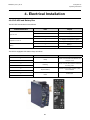
4.2.2 DC Power Input
Caution: External DC Power input (if used) must conform to the Input Supply Voltage specification
given in Chapter 10, and must not be located inside the Touchpoint Pro wall mounted enclosure.
The voltage supply requires an overcurrent protection rated in accordance with the rating plate on the
specific system.
The supply must be able to be isolated by means of a switch or circuit breaker, which must be suitably
located, easily reached and clearly marked as the Touchpoint Pro disconnect device.
The wiring used between the isolator and Touchpoint Pro must be appropriately rated and approved.
Ensure that the power supply is able to maintain sufficient voltage level for the connected field devices.
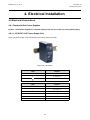
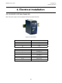
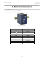
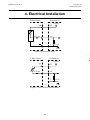
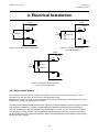
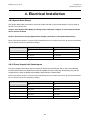
4.2.3 DC Power Output
Touchpoint Pro power output can be adjusted to between 24 Vdc and 28 Vdc (default 24 Vdc).
Touchpoint Pro power supplies include a DC OK relay, which is closed when the output voltage reaches the
adjusted output voltage level, and opens when the output voltage dips more than 10% below the adjusted
output voltage level.
The DC OK Relay has a maximum rating of 60 Vdc 0.3 A, 30 Vdc 1 A or 30 Vac 0.5 A resistive load and a
minimum permissible load of 1 mA at 5 Vdc.
Note: If the UPS Module with battery backup option is being used, ensure that the power supply is adjusted
to at least 26 Vdc to ensure sufficient charging of the battery.
Note: If the Power Redundancy Module is being used, ensure that both power supplies are set to the same
output voltage.
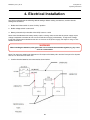
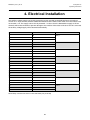
4.3 Cabling Requirements
WARNING
All cabling must be appropriately rated and approved in accordance with local, national and
company regulations. Additionally, cabling must satisfy requirements defined in the manuals of
connected field devices, in particular if the field device is certified for use in a hazardous location.
All cabling should meet local, national and site regulations, and be suitable for the operating environment.
Cable should be appropriately rated and approved. Bootlace ferrules must be used on all terminations.
For installation in Canada and the USA, for both ordinary and hazardous locations, all connections, cabling,
overcurrent protection and installations must strictly adhere to both the National Electrical Code (NEC) and
the Canadian Electrical Code (CEC).
45
MAN0923_Issue 3_04/15
Touchpoint Pro
Operating Instructions
4. Electrical Installation
4.3.1 Ring Network
The external ring network cabling should be shielded twisted pair cable. The terminals will accept a
maximum wire size of 1.5 mm2.
4.3.2 Field devices
Field device cabling should be appropriate to the area classification, and in accordance with the device
manufacturer’s recommendations. Refer to local and national regulations where appropriate, and the field
device manual. All sensor field cables must be screened in order to ensure correct operation of the system
and to meet European Standards for RFI and EMC.
Ensure that the maximum loop resistance is not exceeded, as specified by the device manufacturer.
Take account of voltage drops due to line resistance to ensure that the correct voltage level is present at the
field device, as specified by the device manufacturer.
The I/O modules will accept wire sizes to a maximum of 2.5 mm².
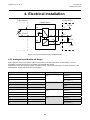
4.3.3 Power Supplies
Power supplies can be in the range 100 - 240 Vac, 50/60 Hz, single phase, or 24 Vdc nominal (18 - 32 Vdc).
Use approved supply wiring rated in accordance with the rating plate on the specific system, in accordance
with local and national regulations. The Touchpoint Pro power supplies will accept wire sizes in the range
0.5 - 6 mm2 (solid wire), 0.5 - 4 mm2 (stranded wire) or 20 - 10 AWG.
4.3.4 Bus interfaces
Please refer to the appropriate appendix.
4.3.5 Ethernet
Ethernet cable must be CAT5e or CAT6 Ethernet cable terminated to TIA/EIA-568B standard. The cable
should have shielded RJ45 plugs with the shield of the cable connected to the metal body (shield) of the
connector plug. The cable length should not exceed 100 m. The Ethernet cable should be fitted through a
gland.
4.3.6 Touchpoint Pro Battery Box
The cable between the Touchpoint Pro System UPS and the Touchpoint Pro Battery Box must be 4 mm2,
UL/CSA approved wiring material, tri-rated (105 °C). The maximum cable length between the Battery Box
and the UPS is 5 m. Bootlace ferrules must be used on all terminations.
46
MAN0923_Issue 3_04/15
Touchpoint Pro
Operating Instructions
4. Electrical Installation
4.4 Cabling Requirements – Additional information for assembly by
system integrators
4.4.1 24 Vdc Power - Controller
For the 24 Vdc power cabling the following power cabling specification is required:
• 2-wire cable
• Diameter appropriate to the current load (TB1 on the Control Module will accept a maximum wire size of 1.5 mm². The power connector to the DIN rail will accept a maximum wire size of 6 mm²)
•Shielded
4.4.2 Internal network connections
Please refer to the Ring Network cable recommendations given above.
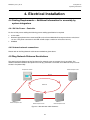
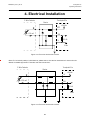
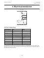
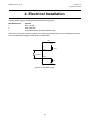
4.5Ring Network Distance Restrictions
The total round trip distance of the Touchpoint Pro network must not exceed 3 km (1.86 miles). The
distance between individual Touchpoint Pro units (e.g. between a Controller and a Remote Unit) must not
exceed 1 km (0.62 miles).
Touchpoint Pro Controller
Remote Touchpoint Pro Unit
Max 1km
Max 3 km
Remote Touchpoint Pro Unit
Remote Touchpoint Pro Unit
Remote Touchpoint Pro Unit
Figure 4.1 Max allowed cable distances
47
MAN0923_Issue 3_04/15
Touchpoint Pro
Operating Instructions
4. Electrical Installation
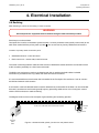
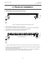
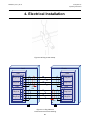
4.6 Earthing
Note: Earthing is known as Grounding in some countries.
WARNING
All Touchpoint Pro equipment must be earthed using the earth terminals provided.
Earth loops must be avoided.
Touchpoint Pro must be connected to protective earth. Connect protective earth (usually mains earth) to the
. Do not remove any factory fitted earth connections.
earth stud marked with the primary earth symbol
Location of primary earth connection point:
• Standard enclosure – lower left corner
• Rack mount unit – reverse side, lower left corner
The screen of the Ring Network cable and the screens of field device cables should be connected to earth
at the controller, preferably to a clean instrument earth.
The Wall mount enclosures contain a pre-fitted screen bar for earthing the field cables.A suitable
termination is provided for the ring cables and earth terminals for all others.
It is recommended that an earth screen bar be installed in the Touchpoint Pro enclosure / rack to connect
the field and network cable screens.
If armoured or steel wire braided cable is used for field devices, and earthed in the field, it is recommended
that care is exercised to avoid earth (ground) loops by preventing cable armour from coming into contact
with the TPPR enclosure or cable screening.
The diagrams below show some examples of good earthing and screening practice:
Three Core Cable with Screen Earthed at Contoller
Junction
Box
Sensor
P
Incoming
Client
Earth
Figure 4.2 Screened cable, plastic junction box and plastic sensor
48
MAN0923_Issue 3_04/15
Touchpoint Pro
Operating Instructions
4. Electrical Installation
• Instrument Earth is preferred to connect the cable screen
• Risk is that screen is connected at both ends = earth loops
Three Core Cable with Screen Earthed at Contoller
Junction
Box
Sensor
P
Incoming
Client
Earth
Figure 4.3 Screened cable, metal junction box and/or sensor
• Instrument Earth is preferred to connect the cable screen
• Care must be taken to isolate the screen at the junction box, e.g. terminate it in a spare terminal
• The metal sensor / junction box must be connected to Protective Earth
• Risk is that screen is connected at both ends = earth loops
Armour
Screen
Three Core Cable with Screen and Armour with Screen Earthed at Controller
and Armour Earthed in Field
Junction
Box
Sensor
P
Incoming
Client
Earth
Figure 4.4 Screened cable with armour (wire or braid) with plastic junction box and plastic sensor
• The armour must be connected to Protective Earth at the sensor, and the screen should be connected to
the enclosure’s common earth (ground) rail.
• Care must be exercised to prevent contact between cable armour and cable screen, and between
cable armour and the enclosure in order to prevent ground loops occurring.
49
MAN0923_Issue 3_04/15
Touchpoint Pro
Operating Instructions
4. Electrical Installation
Armour
Screen
Junction
Box
Three Core Cable with Screen and Armour with Screen Earthed at Controller
and Armour Earthed in Field
Sensor
P
Incoming
Client
Earth
Figure 4.5 Screened cable with armour (wire or braid) with metal junction box and/or sensor
• The armour must be connected to Protective Earth and the screen should be connected to the
Touchpoint Pro enclosure’s common earth (ground) rail
• The metal sensor/junction box must be connected to Protective Earth
• The armour would typically be connected through a metal cable gland to a metal JB or controller enclosure, but great care must be taken to avoid ground loops by preventing the armour coming into
contact with either the enclosure or the cable screening.
4.7EMC / RFI Considerations
For installations in Europe, all electrical equipment connected to the system should comply with the EMC
Directive 2004/108/EC. For non-European installations, electrical equipment connected to the system
should comply with applicable national or international EMC standards.
All external and field cables connected to the Touchpoint Pro system must be screened in order to ensure
correct operation of the system and to meet European Standards for RFI and EMC. The cable screen
should be properly terminated to earth at one end only (the Touchpoint Pro side) to avoid earth loops.
All screens should be terminated at the instrument earth bar provided in the enclosure.
External cabling associated with the Touchpoint Pro system should be isolated from other equipment
cabling, in particular any high voltage or high current cabling.
50
MAN0923_Issue 3_04/15
Touchpoint Pro
Operating Instructions
4. Electrical Installation
4.8 Electrical Connections
4.8.1 Touchpoint Pro Power Supplies
Caution - TPPR power supplies are supplied already wired. Do not modify any factory fitted cabling
4.8.1.1 120 W DC 24 V Power Supply Unit
Note: The power supply units are equipped with spring-clamp terminals.
Figure 4.6 120 W PSU
Label
Purpose
N
AC Supply Neutral
L
AC Supply Line
Earth
Label
Purpose
+
DC Output +V
+
DC Output +V
-
DC Output -V
-
DC Output -V
DC OK
Relay Contact
DC OK
Relay Contact
51
MAN0923_Issue 3_04/15
Touchpoint Pro
Operating Instructions
4. Electrical Installation
4.8.1.2 240 W DC 24 V Power Supply Unit
Note: The power supply units are equipped with spring-clamp terminals.
Figure 4.7 240 W PSU
Label
Purpose
N
AC Supply Neutral
L
AC Supply Line
Earth
Label
Purpose
+
DC Output +V
+
DC Output +V
-
DC Output -V
-
DC Output -V
DC OK
Relay Contact
DC OK
Relay Contact
52
MAN0923_Issue 3_04/15
Touchpoint Pro
Operating Instructions
4. Electrical Installation
4.8.1.3 480 W DC 24 V Power Supply Unit
Note: The power supply units are equipped with spring-clamp terminals.
Figure 4.8 480 W PSU
Label
Purpose
N
AC Supply Neutral
L
AC Supply Line
Earth
Label
Purpose
+
DC Output +V
+
DC Output +V
-
DC Output -V
-
DC Output -V
DC OK
Relay Contact
DC OK
Relay Contact
53
MAN0923_Issue 3_04/15
Touchpoint Pro
Operating Instructions
4. Electrical Installation
4.8.2 Power Redundancy Module
Failure
Monitor
Input Input
1
2
24V, 20A DCOK
L
Power
Supply
Redundancy
Module
AC
N PE
Output
24V, 20A DCOK
Power
Supply
L
AC
N PE
20A
Load
Figure 4.9 Power Redundancy Module
Label
Purpose
Input 1 +
DC Supply 1 +V
Input 1 -
DC Supply 1 -V
Input 2 +
DC Supply 2 +V
Input 2 -
DC Supply 2 -V
Output +
DC Output +V
Output -
DC Output -V
54
MAN0923_Issue 3_04/15
Touchpoint Pro
Operating Instructions
4. Electrical Installation
4.8.3 DC-UPS and Battery Box
The DC-UPS connections are as follows:
Terminal Identification
Label
Purpose
+
DC Supply +V
-
DC Supply -V
-
DC Supply -V (spare)
+
+V Supply to Touchpoint Pro system
-
-V Supply to Touchpoint Pro system
+
Battery +
-
Battery -
Label
Purpose
Ready
Contact is closed when both batteries are
charged, all OK
Buffering
Contact is closed when UPS has switched
to battery power
Replace Battery
Contact is closed when a battery quality
fault is detected
Input DC 24 V
Output DC 24 V 20 A
Battery
The UPS is equipped with status relays as follows:
Terminal Identification
1
2
3
4
5
6
7
8
Inhibit
55
DO NOT USE
MAN0923_Issue 3_04/15
Touchpoint Pro
Operating Instructions
4. Electrical Installation
The UPS is shipped with the following default settings. Before making connections, confirm that the
settings are as follows:
1. Buffer time limiter switch is set to “infinity” position
2. Buffer voltage switch is set to 24V
3. Battery size switch (on the side of the UPS) is set to >10 Ah
Note: If the UPS Module with battery backup option is being used, ensure that the power supply output
voltage is adjusted to at least 26 Vdc to ensure sufficient charging of the battery. To adjust the voltage,
locate the potentiometer labelled 24-28 Vdc on the front of the power supply, and adjust it using a cross
headed screwdriver.
WARNING
When handling the batteries, take great care not to connect the terminals together, e.g. by a tool
such as a screwdriver.
Note: The maximum cable length between the Touchpoint Pro Battery Box and the Touchpoint Pro System
UPS is 5 m. Wire size must be 4 mm2.
1. Confirm that the batteries are connected as shown below:
56
MAN0923_Issue 3_04/15
Touchpoint Pro
Operating Instructions
4. Electrical Installation
2. Before making connections, ensure that the isolator switch is in the OFF (down) position
3. Connect the incoming cable from the UPS as follows:
UPS
Battery Box
Terminal Identification
Terminal Identification
Purpose
Battery +
1
DC Voltage +
Battery -
3
DC Voltage -
Note: The isolator is designed to be located in the centre of the DIN rail, do not move it from this location.
4. Connect the Touchpoint Pro Battery box to protective earth. An earth stud (M8) is provided for this
purpose. Refer to local or national codes of practice for equipotential bonding. Honeywell Analytics recommends a minimum wire size of 6 mm2 (10 AWG).
4.8.4 Analogue Input Module 4-20 mA
Note: The Analogue Input Module mA operates in current sink mode only.
Note: Channel wiring is from left to right for terminals on the top and bottom of the module. It is not
possible to move a plug from top to bottom of a module after wiring.
Please ensure correct wiring by system verification tests. See Commissioning, First Time Switch On, and
Maintenance, Testing the Touchpoint Pro System
The Analogue Input Module mA (AIM mA) accepts 4-20 mA current source signals from field devices (the
module operates in current sink mode only).
The module can supply 18-32 Vdc (24 Vdc nominal) to the field devices at a maximum current of 1 A per
channel, with the additional limitation that the total current drawn from the module must not exceed 2 A at
65 °C ambient or 4 A at 55 °C ambient.
Terminal Identification
Label
Channel
Field device
1
+V
Input 1
+24 Vdc
2
SIG
4 - 20 mA signal
3
-V
0 Vdc
4
+V
5
SIG
4 - 20 mA signal
6
-V
0 Vdc
7
+V
8
SIG
4 - 20 mA signal
9
-V
0 Vdc
10
+V
11
SIG
4 - 20 mA signal
12
-V
0 V dc
Input 2
Input 3
Input 4
57
+24 Vdc
+24 Vdc
+24 Vdc
MAN0923_Issue 3_04/15
Touchpoint Pro
Operating Instructions
4. Electrical Installation
Touchpoint Pro
3 Wire Detector
+24 Vdc
+V
SIG
4-20 mA
-V
101 Ω
0 Vdc
Figure 4.10 Three wire device
2 Wire Detector
Touchpoint Pro
+24 Vdc
+
+V
4-20 mA
SIG
-V
101 Ω
0 Vdc
Figure 4.11 Two wire loop powered device
58
MAN0923_Issue 3_04/15
Touchpoint Pro
Operating Instructions
4. Electrical Installation
2 Wire Detector
Barrier
Touchpoint Pro
+24 Vdc
+V
4-20 mA
SIG
-V
101 Ω
0 Vdc
Figure 4.12 Two wire device with a barrier
Note: For intrinsically safe (I.S.) field devices, please refer to the device manufacturer’s instructions for
details of suitable approved I.S. barriers and interconnections.
2 Wire Detector
Barrier
Touchpoint Pro
+24 Vdc
+V
4-20 mA
SIG
-V
101 Ω
0 Vdc
Figure 4.13 Two wire device with a barrier
59
MAN0923_Issue 3_04/15
Touchpoint Pro
Operating Instructions
4. Electrical Installation
2 Wire Detector
Touchpoint Pro
Isolated Barrier
+24 Vdc
+ve
+V
4-20 mA
SIG
+vs
-ve
-vs
-V
101 Ω
0 Vdc
Figure 4.14 Two wire device with a isolated barrier
4.8.5 Analogue Input Module mV Bridge
Note: Channel wiring is from left to right for terminals on the top and bottom of the module. It is not
possible to move a plug from top to bottom of a module after wiring.
Please ensure correct wiring by system verification tests. See Commissioning, First Time Switch On, and
Maintenance, Testing the Touchpoint Pro System
Terminal Identification
Label
Channel
Field device
1
S
Input 1
Sensitive (+)
2
01
Signal
3
NS
Non-sensitive (-)
4
S
5
01
Signal
6
NS
Non-sensitive (-)
7
S
8
01
Signal
9
NS
Non-sensitive (-)
10
S
11
01
Signal
12
NS
Non-sensitive (-)
Input 2
Input 3
Input 4
60
Sensitive (+)
Sensitive (+)
Sensitive (+)
MAN0923_Issue 3_04/15
Touchpoint Pro
Operating Instructions
4. Electrical Installation
Catalytic Detector
Touchpoint Pro
+
S
S
01
S
NS
_
NS
Figure 4.15 Catalytic detector
4.8.6 Digital Input Module
Note: Channel wiring is from left to right for terminals on the top and bottom of the module. It is not
possible to move a plug from top to bottom of a module after wiring.
Please ensure correct wiring by system verification tests. See Commissioning, First Time Switch On, and
Maintenance, Testing the Touchpoint Pro System.
DIMs have two modes of operation. A DIM channel may be configured to generate an alarm, fault or
warning signal when activated.
Alternatively, a DIM channel may be configured to provide remote control of a selected group of one or
more input / output channels. The DIM may be used to remotely reset, inhibit, or acknowledge the selected
channels. When used for inhibit, repeated activation toggles the inhibit state of the selected channels.
Terminal Identification
Label
Channel
1
+
Input 1
2
3
-
4
+
Input 2
5
6
-
7
+
Input 3
8
9
-
10
+
Input 4
11
12
-
61
MAN0923_Issue 3_04/15
Touchpoint Pro
Operating Instructions
4. Electrical Installation
TPPR
TPPR
+24 Vdc
+24 Vdc
1 KΩ
+
REOL
SWITCH
1 KΩ
SWITCH
10 KΩ
-
75 Ω
75 Ω
0 Vdc
0 Vdc
Figure 4.16 Unsupervised configuration
Figure 4.17 Supervised for open
circuit configuration
TPPR
+24 Vdc
+
1 KΩ
RINL
REOL
10 KΩ
2.7 KΩ
SWITCH
75 Ω
0 Vdc
Figure 4.18 Supervised for open and
short circuit configuration
4.8.7 Relay Output Module
Note: Channel wiring is from left to right for terminals on the top and bottom of the module. It is not
possible to move a plug from top to bottom of a module after wiring.
Please ensure correct wiring by system verification tests. See Commissioning, First Time Switch On, and
Maintenance, Testing the Touchpoint Pro System
The Relay Output Module (ROM) provides relay outputs to switch field devices such as sounders, beacons
and actuators. In addition, an auxiliary voltage supply is available to provide power to such devices.
The relay contacts have a recommended range of application ≥ 12 Vdc, 10 mA. The maximum contact
current rating is 5 A per channel, with the additional limitation that the maximum contact current rating
for the module is 8 A. An overcurrent protection device should be fitted to prevent higher current flowing
through the relay contacts.
62
MAN0923_Issue 3_04/15
Touchpoint Pro
Operating Instructions
4. Electrical Installation
The auxiliary voltage supply can provide 18-32 Vdc (24 Vdc nominal) to the field devices at a maximum
current of 1.5 A per channel, with the additional limitation that the total current drawn from the module must
not exceed 1.5 A. The supply is short circuit protected – if a short circuit is detected the supply to all four
channels will be disconnected to prevent damage to the module. If the cause of the short circuit is removed,
the auxiliary voltage supply will be restored automatically.
Terminal Identification
Label
Channel
1
NO
Relay 1
2
NC
3
C
4
NO
5
NC
6
C
7
NO
8
NC
9
C
10
NO
11
NC
12
C
Relay 2
Relay 3
Relay 4
13
V Aux 1
14
+V
15
-V
16
V Aux 2
17
+V
18
-V
19
V Aux 3
20
+V
21
-V
22
V Aux 4
23
+V
24
-V
Note: Relay contacts are shown in the shelf state (not powered)
63
MAN0923_Issue 3_04/15
Touchpoint Pro
Operating Instructions
4. Electrical Installation
Touchpoint Pro
+24 Vdc
VAux+
VAux0 Vdc
NO
NC
C
Figure 4.19 ROM connection
4.8.8 Ring Coupling Module
Terminal Identification
Label
Channel
1
+
Ring A In
2
Drain
3
-
4
+
5
Drain
6
-
7
+
8
Drain
9
-
10
+
11
Drain
12
-
Ring B Out
Ring B in
Ring A Out
The ring cable must have the drain wire terminated at the Ring Coupling Module and Control Module drain
terminals. The ring screen must be connected to the instrument bar at the Ring A Out and Ring B In side of
the cable with the clamps provided.
64
MAN0923_Issue 3_04/15
Touchpoint Pro
Operating Instructions
4. Electrical Installation
Figure 4.20 Ring screen clamp
Local
Remote
CMA
+
+
Ring B in
Drain
RCM
+
Ring A in
+
Ring B out
Drain
Ring A out
+
+
Ring B out
Drain
Screen
Bar
Ring A in
Screen
Bar
Figure 4.21 Ring Network
connections and screen earthing
65
+
Ring A out
+
Ring B in
Drain
MAN0923_Issue 3_04/15
Touchpoint Pro
Operating Instructions
4. Electrical Installation
4.8.9 System State Relays
The System State Relay connections are found at TB4 and TB5 on the Control Module. They are rated at
30 Vdc 3 A or 250 Vac 3 A.
Caution: If the System State Relays are being used to switch AC voltages, an overcurrent protection
device must be included
Caution: Isolate all incoming supplies before making connections to the System State Relays
Note: It may be necessary to remove the Control Module Cover to make connections to the Control Module.
Do not remove any factory fitted earth cabling
Terminal
System Failure Relay
System Fault Relay
TB4
TB5
1
SIS_Fail_COM
SIS_Fault_COM
2
SIS_Fail_NO
SIS_Fault_NO
3
Screen_TB4
Screen_TB5
4.8.10 Power Supply Unit Status Inputs
The Power Supply Units Status Input connections can be found at TB8 and TB9 on the Control Module.
The PSU Status Inputs are Digital Input channels available for PSU monitoring. Alternatively, they can be
configured to be used as Global Acknowledge, Global Reset or Global Inhibit.
Note: It may be necessary to remove the Control Module Cover to make connections to the Control Module.
Do not remove any factory fitted earth cabling.
Terminal
System Failure Relay
System Fault Relay
TB8
TB9
1
PSU1_Stat 1
PSU3_Stat 1
2
PSU1_Stat 2
PSU3_Stat 2
3
PSU2_Stat 1
PSU4_Stat 1
4
PSU2_Stat 2
PSU4_Stat 2
5
Screen_TB8
Screen_TB9
66
MAN0923_Issue 3_04/15
Touchpoint Pro
Operating Instructions
4. Electrical Installation
The PSU Status Inputs are supplied with the following configuration.
PSU Status Input 1 2 3 4 Function
PSU – DC OK
UPS – BAT RDY
UPS – BAT RPL
Temperature Sensor (Forced Ventilation Only)
If the UPS or the forced ventilation options are not being used, those inputs can be configured by the user
to act as Global Acknowledge, Global Reset or Global Inhibit.
TPPR
+24 Vdc
Stat 1
1.0 KΩ
PSU Status
Stat 2
75 Ω
0 Vdc
Figure 4.21 PSU Status Input
67
MAN0923_Issue 3_04/15
Touchpoint Pro
Operating Instructions
5. User Interface
5.1 General
System interfaces consist of:
• Interface software with three ways to access
Touchscreen for normal system operation, maintenance and configuration
Licensed Web Server for remote access to view normal system operation
Licensed PC Configuration Software (optional) for convenient system configuration
• Accept and reset buttons on the front panel of the Touchpoint Pro Controller
• Power, Alarm, Fault and Inhibit LEDs on the front panel of the Touchpoint Pro Controller
• Buzzer on the Touchpoint Pro Controller
Further Interfaces consist of:
• Two master relays, System Failure and System Fault
• Connections for SD Card and USB memory device
• 10/100 Mbps Ethernet connection
• Optional digital bus interface
The interface software has two distinct modes of operation – Configuration Mode and Visualisation Mode,
Within each mode, access to certain functions is restricted by the use of password protected access
levels. There are four hierarchical access levels - View is available to all users while Operator, Maintenance
Engineer and Administrator are password protected. Each user can be assigned one access level.
Access to certain functions is also restricted via the Web Server for safety reasons.
5.2 Access Levels
The table below details the access levels for the User Interface. The highest level of password protected
access is Administrator, then Maintenance Engineer, then Operator. Broadly speaking, the Administrator
can commission modules and configure channels, the Maintenance Engineer can edit channel configuration
and do calibration, and the Operator can interact with the system during normal day-to-day operation such
as acknowledging and resetting events. The table also shows which functions are not available via the Web
Server for safety reasons (for example, Calibration).
Touchpoint Pro is supplied with a default Administrator level account. For security reasons this will be
attached to the system touchscreen. When the system is configured, at least one new Administrator
account should be created. The default Administrator should then log out and then log back in as the new
Administrator, and should then delete the default Administrator account to prevent unauthorized access.
The Administrator can create other users with Administrator level access or lower and the Maintenance
68
MAN0923_Issue 3_04/15
Touchpoint Pro
Operating Instructions
5. User Interface
Engineer can create users with Engineer level access or lower.
Caution: Forgotten or deleted passwords cannot be recovered. It is therefore advisable to have two
Administrators so that one can replace the passwords of any other users.
Note: Only Administrators can end another user’s active session, even if it has timed out.
Note: The user login times out after 20 minutes of inactivity.
Screen Name
Web
Administrator Maintenance Operator
Engineer
View
System Status
Active Events
Y
Y
Y
Y
Inputs
Y
Y
Y
Y
Outputs
Y
Y
Y
Y
Input Detail
Y
Y
Y
Y
Trend
Y
Y
Y
Y
Y
Y
Y
Y
Trend Configuration
Security
Calibration
No
Y
Y
N
N
Span Adjust
No
Y
Y
N
N
Zero Adjust
No
Y
Y
N
N
Extras
Y
Y
Y
Y
Event History
Y
Y
Y
Y
SD Card
Y
Y
Y
Y
Help
Y
Y
Y
Y
Service Contact
Y
Y
Y
Y
About
Y
Y
Y
Y
Report
Y
Y
Y
Y
Y
Y
N
N
Diagnostics
Screen Name
No
Web
Administrator Maintenance Operator
Engineer
View
Global Settings
No
Y
Y
N
N
Service Contact Settings
No
Y
Y
N
N
TCP/IP Settings
No
Y
Y
N
N
Modbus Settings
No
Y
Y
N
N
Panel Configuration
No
Y
Y
N
N
Regional Settings
No
Y
Y
N
N
Software Update
No
Y
Y
N
N
Sensor Catalogue Update
No
Y
Y
N
N
69
MAN0923_Issue 3_04/15
Touchpoint Pro
Operating Instructions
5. User Interface
System Configuration
No
Y
Y
N
N
Channel Name Settings
No
Y
Y
N
N
View Channel Configuration
No
Y
Y
N
N
CCB Management
No
Y
N
N
N
CCB Configuration
No
Y
N
N
N
User Management
No
Y
Y
N
N
System Setup
No
Y
Y
N
N
Channel Pop-Up
No
Y
N
N
N
Channel Source Data
No
Y
N
N
N
Commission Channel
No
Y
N
N
N
Decommission Channel Pop-Up
No
Y
N
N
N
Module Pop-Up
No
Y
N
N
N
Commission Module
No
Y
N
N
N
Replace Module
No
Y
N
N
N
Replace Module Pop-Up
No
Y
N
N
N
Remove Module Pop-Up
No
Y
N
N
N
Network Scan Pop-Up
No
Y
N
N
N
Field Device Selection
No
Y
N
N
N
Sensor Settings
No
Y
N
N
N
Range Settings
No
Y
N
N
N
Display Settings
No
Y
N
N
N
Suppression Settings
No
Y
N
N
N
Threshold Alarm 1 Settings
No
Y
Y
N
N
Threshold Alarm 2 Settings
No
Y
Y
N
N
Threshold Alarm 3 Settings
No
Y
Y
N
N
Threshold Alarm Hysteresis
No
Y
Y
N
N
STEL Alarm Settings
No
Y
Y
N
N
Screen Name
Web
Administrator Maintenance Operator
Engineer
View
LTEL Alarm Settings
No
Y
Y
N
N
Rate Alarm Settings 1
No
Y
Y
N
N
Rate Alarm Settings 2
No
Y
Y
N
N
Rate Alarm Settings 2
No
Y
Y
N
N
Inhibit Delay Settings
No
Y
Y
N
N
Signal Range Fault Settings
No
Y
Y
N
N
Gas Range Fault Settings
No
Y
Y
N
N
70
MAN0923_Issue 3_04/15
Touchpoint Pro
Operating Instructions
5. User Interface
Calibration Reminder Settings
No
Y
Y
N
N
Calibration Signal Settings
No
Y
Y
N
N
Calibration Span Gas Settings
No
Y
Y
N
N
Inhibit Signalling Settings
No
Y
Y
N
N
Fault Signalling Settings 1
No
Y
Y
N
N
Custom Fault X Detail Settings
No
Y
Y
N
N
Fault Signalling Settings 2
No
Y
Y
N
N
Digital Input Settings
No
Y
Y
N
N
Alarm Settings
No
Y
Y
N
N
Remote Interaction Settings
No
Y
Y
N
N
Remote Group Interaction Settings
No
Y
Y
N
N
Relay Output Settings
No
Y
Y
N
N
Relay Output Settings
No
Y
Y
N
N
Relay Timing Settings
No
Y
Y
N
N
Input Channel Pre-Selection
No
Y
Y
N
N
Cause & Effect Matrix
No
Y
Y
N
N
SysInteract. Acknowledge
Y
Y
Y
N
SysInteract. Reset
Y
Y
Y
N
SysInteract. Inhibit
Y
Y
N
N
SysInteract. Clear Inhibit
Y
Y
N
N
System Interaction
SysInteract. Force Output
No
Y
Y
Y
N
SysInteract. Clear Force Output
No
Y
Y
N
N
71
MAN0923_Issue 3_04/15
Touchpoint Pro
Operating Instructions
5. User Interface
5.3 User Interface Software
The User Interface Software is accessible in three different ways - by local touchscreen at the Touchpoint
Pro Controller, by Web Server, and by the optional PC Configuration Software. A detailed menu structure of
the software is given in the Appendix - User Interface Software Menu Structure.
Touchpoint Pro does not need a user licence but, for security reasons, the optional PC Config and Web
Server software do.
Please contact your local Honeywell supplier or distributor to obtain a 12-month user licence. They will
need your Company details, a valid e-mail address, and the serial number of the Touchpoint Pro system.
In return, they will e-mail you the licence token and details on how an authorised Honeywell Engineer can
install it in the system, and details on how to activate the licence on a maximum of five PCs.
You will be notified shortly before the expiry of your licence, and you will have a short licence extension in
which to renew the licence token, if you want to.
Please note that expired licences do not stop Touchpoint Pro from working. They will merely stop
you operating it remotely, and you will have to operate it from the touchscreen instead.
Please save your licence token carefully in case of a PC or system malfunction. While replacement
licences can be reissued or transferred to other PCs within the licence period, lost tokens cannot be
replaced and you will have to purchase a new 12-month one.
When renewing/transferring your licence, you must use (or supply) the same e-mail address that you used
for the original licence. Failing to do so will automatically bill you for a completely new licence.
5.4Local Interface (Touchscreen)
The touchscreen is a resistive type, which can be activated using a finger or a stylus. All interactions are
single tap.
Caution: Do not use sharp objects as damage could be caused to the screen
5.5Web Server
The Web Server is an external interface that provides web clients with data from the Touchpoint Pro
System. This facility allows remote access to Touchpoint Pro to view live status, and analyse event history.
It is also possible to acknowledge, inhibit and reset I/O channels. Calibration and configuration are not
available over the Web Server.
The Web Server supports 5 concurrent web clients, however it does not restrict further users from
connecting. System performance may be degraded in this case.
Note: The Web Server is compatible with Internet Explorer version 8 . Please refer to Chapter 6,
Commissioning for the necessary settings. The following browsers are also supported:
72
MAN0923_Issue 3_04/15
Touchpoint Pro
Operating Instructions
5. User Interface
• Internet explorer 6.0 to 8.0
• Chrome up to V38
• Safari
• Chrome up to V38 on Android devices
5.6PC Configuration Software
The optional PC Configuration Software is optimised for the larger screen of a PC, instead of the local
touchscreen. The menu and navigation are as detailed in the section “Menu Structure” however multiple
screens are combined, reducing the overall commissioning time.
Note: the PC Configuration Software is compatible with Windows 7. Please refer to Chapter 6,
Commissioning for the necessary settings.
5.7SD Card
The SD card is used to store the event history of the system. Touchpoint Pro logs all events and all changes
to input readings. A notification will be given when the SD card is 80% full. If the card is not replaced, a
further notification will be given when it is full, and when data is being overwritten.
Note: A list of the events that are logged is given in Appendix 7 - Events
Caution: The SD Card must remain inserted during normal system operation. When the card is full it
should be replaced immediately
5.8Interfaces
The Control Module has several communication interfaces:
• 10/100 Mbps Ethernet port for connection to a local network, to enable the Web Server function and optional PC Configuration Software
• Connections for the optional dual RS485 Modbus RTU interface
• A USB port for connection to a USB flash drive, which can be used to save reports, backup
and restore configuration, and update software, firmware and the sensor catalogue
Note: The USB Device port is not EMC safe, and is to be used for maintenance mode only. The USB Host
port can take a USB flash drive, which can be left in place provided that it does not foul the cables or
cabinet door.
73
MAN0923_Issue 3_04/15
Touchpoint Pro
Operating Instructions
5. User Interface
WARNING!
SD Memory
Card
Remove top and bottom Plugs
of TB9, TB8, before opening the cover.
5
4
3
2
1
TOP TB9
Screen_TB9
PSU4_Stat 2
PSU4_Stat 1
PSU3_Stat 2
PSU3_Stat 1
BOTTOM TB8
5 Screen_TB8
4 PSU2_Stat 2
3 PSU2_Stat 1
2 PSU1_Stat 2
1 PSU1_Stat 1
Interfaces
System Label
Ethernet
Product Label
USB HOST
Figure 5.1 Control Module cover
Note: Please read the chapter “User Interface” before proceeding
74
Drain_TB6
USB
DEVICE
Made in
XX
2400D1370
TB7
1 2 3 4 5
4 5
A2_OUT
B2_OUT
Drain_TB7
RS-485 Interface 2
TB6
1 2 3
A2_IN
B2_IN
RS-485 Interface 1
B1_OUT
SIS_Fault_NO
Screen_TB5
TB5
1 2 3
SIS_Fault_COM
TB4
1 2 3
SIS_Fail_COM
Drain TB3
Ring AI-
Ring BO-
Ring BO+
TB3
1 2 3 4 5
Ring AI+
Ring BI-
Drain TB2
Ring BI+
Ring AO+
TB2
2 3 4 5
A1_IN
B1_IN
A1_OUT
System State Relays
Ring Network
1
Ring AO-
24V DC
0V
TB1
1 2
SIS_Fail_NO
Screen_TB4
Power Supply
MAN0923_Issue 3_04/15
Touchpoint Pro
Operating Instructions
6. Commissioning
6.1 Introduction
This chapter explains several operations that may be required during commissioning. Users should
complete the First Time Switch On, Set Date Time and Language, Program Users and Passwords, and
if required Setup Web Server. If the PC Configuration Software is being used, complete First Time Switch
On and Set Date, Time and Language, then Setup PC Configuration Software using the touchscreen,
then continue through the procedures using the PC Configuration Software.
If the system was ordered from Honeywell Analytics with default channel configurations, complete the
section Verify Configuration and Program Tags for the Analogue Input channels, before proceeding with
Channel Configuration for the Digital Input and Relay Output channels.
First Time Switch On
Checks that are required on first power up
Set Date, Time and Language
How to set the real time clock and the display language
Program Users and Passwords
How to set up users and access levels
Setup Web Server
How to connect to the web server interface
Setup PC Configuration Software
How to connect to Touchpoint Pro using the PC Configuration Software
Verify Default Configuration and Program Tags
For systems ordered with a default configuration, how to check the
configuration and set site specific tags
Module Configuration
How to configure input / output modules
Channel Configuration
How to configure individual input / output channels and program the cause
and effect matrix
6.2 First Time Switch On
1. Before applying power to the unit, ensure that the wiring to the unit is correct and all electrical
connections are in accordance with Section 4
2. Apply power. Check that the DC supply voltage is between 18 and 32 Vdc. This can be conveniently
checked for example at the Vaux terminals of a Relay Output Module (preferably furthest from the
power source) or at the V+ and V- terminals of an Analogue Input Module
3. The system start up sequence lasts for 3 - 10 minutes depending on the size of the system
4. When start up is completed, Touchpoint Pro will display the System Status screen, indicating the
current status of the system
Note: If Analogue Input mV Bridge channels have been configured but not calibrated, the channels will be in
Inhibit, which will be indicated on the System Status screen.
The Touchpoint Pro Controller System Status Screen is shown below, as it appears on the touchscreen
interface.
75
MAN0923_Issue 3_04/15
Touchpoint Pro
Operating Instructions
6. Commissioning
Login
Home
Extras
Go to Inputs
User is logged in
Active Events Screen
(no active events)
Active Events Screen
(with active events)
Figure 6.1
A full explanation of the aspects used in Normal Operation is given in chapter 7. For Commissioning,
primarily the Login and Extras icons (found in the navigation bar at the top of the screen) will be used.
6.3 Set Date, Time and Language
Note: In the event of power loss, the date, time and language settings will be retained for 3 days. After a
longer time interval please check and re-program if necessary.
1. Login with the default Administrator level details supplied with the system.
Press the Login icon (padlock) in the navigation bar and a prompt will appear for the User Name and Password.
2. From the System Status screen select the Extras icon then Global Settings, then Regional Settings
3. Set the date, time and time zone as required
4. Select the language required (English (default), French, German, Spanish. Italian, Dutch or Russian)
5.Press Save
6. If the time zone or language has been changed, the User Interface software will reboot to apply the
new settings
Note: During the restart of the User Interface software, the Touchpoint Pro system remains available
76
MAN0923_Issue 3_04/15
Touchpoint Pro
Operating Instructions
6. Commissioning
7. Otherwise, use Back and Home to return to the System Status screen
Note: Touchpoint Pro does not adjust automatically for daylight savings time.
Note: If the date and time are changed to a time in the past (for example ending daylight savings time),
Touchpoint Pro will retain the backup of previous data but this backed up data will not be available in the
generated reports.
In the current version there is no provision to check or get the data back and generate the report, though the
data is available in backup.
6.4Program Users and Passwords
The Touchpoint Pro is supplied with a default Administrator login and password attached to the
touchscreen. For security reasons at least one new Administrator account should be created during
commissioning, and the default account should then be deleted. Two Administrator accounts are safer than
one as lost passwords cannot be recovered.
A Honeywell authorised engineer can rescue a locked-out Administrator, but this requires an on-site Service
call and installation of a special token and one-time pass phrase.
Note: Administrator level access is required to create an Administrator level user.
Note: User names and passwords are case sensitive. Operator level users cannot change passwords via PC
Configuration software.
A maximum number of 20 users can be added to the Touchpoint Pro system. An Administrator level user
can create other Administrator and lower level users. An Engineer level user can create other Engineer and
lower level users. It is recommended that, when no longer required, the default user “Touchpoint Pro” is
deleted or has the password changed to prevent unauthorised access.
The following rules apply to user names and passwords:
• The user name must be 4 to 20 characters long
• The password cannot contain the user name
• The password must be 8 to 10 characters long
• The password must contain a mix of letters, numbers and symbols
• The password cannot contain a string of three or more repeated characters
• Passwords with repeated characters may be rejected
Caution: Touchpoint Pro allows login by the same user from different access points (local User
Interface, Web Server etc.). To maintain traceability of system operation and changes, ensure good
discipline is maintained with regard to security of login details.
77
MAN0923_Issue 3_04/15
Touchpoint Pro
Operating Instructions
6. Commissioning
1. If not already logged in, login with a valid engineer or administrator level user name
2. From the System Status screen select the Extras icon then System Configuration
3. Re-enter the password and press Login
4.Select User Management
, and fill in the new user name, password and 5. To add a new user, select the Add User icon
access level. See the Chapter “User Interface” for details of the available access levels
6.Press Add to add the new user
7.Press Back and Home to return to the System Status screen
6.5Setup Web Server
Note: Engineer level access is required
To connect via Web Server, the Touchpoint Pro must be connected to a network. The Touchpoint Pro
Ethernet port is 10/100 Mbps. Ethernet cable must be CAT5e or CAT6 Ethernet cable terminated to
TIA/EIA-568B standard. The cable should have shielded RJ45 plugs with the shield of the cable connected
to the metal body (shield) of the connector plug. The cable length should not exceed 100 m.
Note: Web Server performance will depend on the network infrastructure
Note: The Web Server is optimised for a screen of 1024x768 pixels. For optimum viewing on other screens,
it may be necessary to view full screen and turn off the Internet Explorer status bar.
6.5.1 TCP/IP Settings
Note: Ping service should not be turned off, ports should not be disabled. Pop-ups should be allowed, and/
or Touchpoint Pro should be white-listed.
To access the TCP/IP settings:
1. From the System Status screen select the Extras icon then Global Settings
2. Select “TCP/IP Settings” to display the current values
3. Select “Edit” to change the values as appropriate to the network
4. To access the Web Server from a remote PC connected to the network, navigate to https://
<IP Address>
Note: The Web Server can only be accessed after the Touchpoint Pro system has completed its start up
sequence
Note: If the Subnet Mask is set to 255.255.0.0, this means that the first two bytes of the IP Address must
match both in the controller and the device that is trying to connect to it. For example, if the controller
IP Address is set to 192.168.1.2 it can connect to another device or network that has an IP Address of
192.168.xxx.yyy (where xxx can be any whole number between 0 and 255 inclusive and yyy can be whole
number between 1 and 254 inclusive ).
78
MAN0923_Issue 3_04/15
Touchpoint Pro
Operating Instructions
6. Commissioning
6.5.2 Internet Explorer Settings
To avoid any issues with file downloads, it is necessary to configure some of the Internet Explorer settings
on the PC that is being used:
1. Open Internet Explorer
2. Select Tools -> Internet Options ->Security->Local Intranet->Custom level->Downloads
3. Click on the “Enable” button under “Automatic prompting for file downloads” and under “File download”
4. Select “OK” to return to Internet Options
5. From Tools -> Internet Options select Advanced->Browsing
6. Check the box beside “Display a notification about every script error”
7. Check the box beside “Notify when downloads complete”
8. Select “Apply” to confirm the settings
9. From Tools -> Internet Options select General -> Browsing History -> Settings
10.Under “Check for newer versions of stored pages” click on the “Automatically” button
11.Select “OK” to return to Internet Options
12.Select “Apply” to confirm the settings and “OK” to close the window
6.5.3 Windows Settings
Touchpoint Pro generates reports which can be viewed in Microsoft Excel. To ensure reports are generated
and opened correctly please check the file opening settings in Windows on the PC that is being used:
Windows 7
Windows 7 users will only encounter an issue if the “Always ask before opening this type of file” box
has previously been unchecked. In this case there will be no option to Open or Save the file that is being
downloaded; instead the previous choice will be done automatically. The option to “Confirm open after
download” can only be re-enabled by editing the Windows registry. It is recommended to consult your
company’s IT Support for assistance.
6.6Setup PC Configuration Software (optional)
Note: Engineer level access is required
To connect a PC to Touchpoint Pro via the Ethernet port, the TCP/IP settings in the Touchpoint Pro and the
PC must be configured appropriately.
Note: PC Screen Resolution is limited to 1024 x 768. Other resolutions may show a grey patch, which
does not affect the software operation. Ping service should not be turned off, ports should not be disabled.
Pop-ups should be allowed, and/or Touchpoint Pro should be white-listed.
79
MAN0923_Issue 3_04/15
Touchpoint Pro
Operating Instructions
6. Commissioning
To access the TCP/IP settings:
1. On the Touchpoint Pro Controller touchscreen, from the System Status screen select the Extras icon then Global Settings
2. Select “TCP/IP Settings” to display the current values
3. Select “Edit” to change the values as appropriate to match the PC being used
Note: If the Subnet Mask is set to 255.255.0.0, this means that the first two bytes of the IP Address must
match both in the controller and the device that is trying to connect to it. For example, if the controller
IP Address is set to 192.168.1.2 it can connect to another device or network that has an IP Address of
192.168.xxx.xxx (where xxx can be any whole number between 0 and 255 inclusive). If the Subnet Mask is
set to 255.255.255.0, the first three bytes of the IP Address must match both in the controller and the PC.
4. Install the Touchpoint Pro PC Configuration Software on the PC to be used, and follow the
installation routine
Note: To install the software correctly, it is necessary to run the setup program as an administrator. in
Windows 7, right click on the setup program and select “Run as administrator”.
5. Connect the Touchpoint Pro unit to the network and launch the PC Configuration Software
6. Enter the IP address of the Touchpoint Pro unit and select Connect
7. The Login screen will appear. Enter a valid user name and password
Figure 6.2 Login Details Dialog
The PC Configuration Software follows the same screens as the touchscreen, with the exception that
several screens are combined together. Therefore it is possible to follow through all the instructions in this
chapter to configure the Touchpoint Pro system. For a detailed navigation and menu structure, please refer
to the Appendix - User Interface Software Menu Structure.
80
MAN0923_Issue 3_04/15
Touchpoint Pro
Operating Instructions
6. Commissioning
Figure 6.3 PC Configuration Interface
6.7Verify Default Configuration and Program Tags
Note: Read this section ONLY if your system has been programmed by Honeywell Analytics with the default
configuration during manufacture. Otherwise proceed to section 6.8
If the system has been delivered with a default configuration, then all Analogue Input channels (mA and mV)
have been configured. This section explains how to verify that the channel configuration is correct, and how
to program any tags that are required.
Note: It is necessary to configure any Digital Input channels and all Output channels
Note: Engineer level access is required
1. If not already logged in, login with a valid engineer level user name
2. From the System Status screen select the Extras icon then System Configuration
3. Re-enter the password and press Login
4.Select System Setup
5. The screen will show a list of all installed I/O modules and Control Centre Board(s)
6. Press the + beside each module to expand and show the four channels of that module
7. Select the required channel, press the Menu icon
and select View Configuration
8. Use the Next and Previous buttons to step through the configuration settings and verify that they are as expected. If any settings are incorrect, please refer to the section “Editing a configured channel”
9.Press Exit
10.Select the channel again, press the Menu icon and select Edit Configuration
11.From the menu window select Channel Name Settings
12.The screen will show the current location tag and custom ID
13.Enter the required values in the field New Value and press Send
81
MAN0923_Issue 3_04/15
Touchpoint Pro
Operating Instructions
6. Commissioning
14.The system will return the new value, press Accept to confirm
15.Press Exit and close the menu window
16.Repeat steps 7 – 15 for each configured channel
17. Proceed to section 6.8
Figure 6.4 System Setup Data
6.8 Commission Input / Output Modules
Note: Administrator level access is required
1. If not already logged in, login with a valid administrator level user name
2. From the System Status screen select the Extras icon then System Configuration
3. Re-enter the password and press Login
4.Select System Setup
5. If this is a first time configuration, the system will indicate that the Ring network must be initialised. Press the Ring Network icon
6.
The screen will display the System Setup tree list of all Input / Output modules , PSU Status Inputs and
Control Centre Board(s) installed on the system. The modules are displayed in the order left to right on
the communication / power rail (looking at the rail), and in the direction of Ring A round the complete system (if remote units are being used)
to initialise the network manually
7. Select the required module, press the Menu icon
and select Commission Module
8. Select a module ID number between 1 and 48 (the default is the next available number) and press Send to send it to the system
9. The system will then return the value, which will be displayed on the screen. Confirm that it is correct
and press Accept for the setting to take effect
10.Repeat for all un-commissioned modules on the system
82
MAN0923_Issue 3_04/15
Touchpoint Pro
Operating Instructions
6. Commissioning
Note: After network initialisation, the Input / Output modules are shown according to their physical
order on the Ring A network (clockwise). As soon as the module ID is assigned (Input / Output module
is commissioned), the Input / Output modules will be sorted according to the assigned module ID (M01,
M02, etc.). If there is a combination of commissioned and un-commissioned Input / Output modules on the
network, the commissioned modules are shown below the un-commissioned modules.
Note: The LEDs on the module will indicate flashing green when the module is un-commissioned and solid
green after commissioning
Note: It is good practice to command the Control Centre Board to remove modules before physically
removing them, even if you consider the module(s) to be unserviceable or beyond repair. (The Remove
Module button is directly underneath the Commission Module button; just touch the ID of the module you
want to remove, and then touch Remove Module. Confirm the ID is correct, and then touch Yes to carry out
the action. The removal is added to the event log and a red alarm icon is shown in the menu bar.)
Note: If the Ring Network does not initialise please refer to Chapter 9 - Problem Solving.
6.9Channel Configuration
Note: Administrator level access is required to commission a channel, but Engineer level access can be
used to edit many of the parameters. Please refer to User Interface, Access Levels for details.
6.9.1 Introduction
Individual channels can be configured in several ways – either from the built in sensor catalogue (for
Analogue Input modules only), by completing a full custom configuration, or by copying a previously
configured channel. When the sensor catalogue or the copy function is used, only the Channel ID and the
tags must be programmed. The rest of the configuration is populated automatically.
Note: If a channel is configured from the sensor catalogue or copied from another channel, it is possible to
edit individual settings afterwards (see section “Editing a Configured Channel”).
The configuration software populates the parameters with appropriate default values. To change any
parameter, enter the new value and press Send to send it to the system. The system will then return the
value, which will be displayed on the screen, and the user must press Accept for the setting to take effect.
This is to allow the user to verify that the correct value has reached the system.
New values can be entered in various ways:
• Free text (e.g. location tag)
• Numeric keypad
• Check / uncheck a box (e.g. to toggle an alarm between latching and non-latching)
• Select an option by checking a radio button
• Select from a list of available options (e.g. channel number)
The configuration is designed to be simple to follow on the screen. However Appendix 2 should be used as
a reference for detailed definitions of all the parameters, as well as the default settings and available ranges.
Caution: It is important to understand the definition of a parameter to avoid unexpected or potentially
unsafe behaviour of the system. Please refer to the detailed definitions in the appendix regarding the
meaning of a parameter.
83
MAN0923_Issue 3_04/15
Touchpoint Pro
Operating Instructions
6. Commissioning
6.9.2 Configuring a Channel
Note: Have the configuration information to hand
Note: When you enter the System Setup menu, a configuration timeout is active separate to the user login
timeout. If no values are sent to the system for 20 minutes, you will be logged out of configuration. If a first
time channel configuration has not been completed, all changes will be erased and the channel will be
decommissioned.
To configure an individual channel:
1. If not already logged in, login with a valid administrator level user name
2. From the System Status screen select the Extras icon then System Configuration
3. Re-enter the password and press Login
4.Select System Setup
5. The screen will show the system setup tree listing of all installed I/O modules, PSU Status Inputs and
Control Centre Board(s)
6. Press the + beside each module to expand and show the four channels of that module
7. Select the required channel, press the Menu icon and select Commission Channel
Caution: The I/O Module will be set into Configuration State if configuration is attempted for any of
its channels (either Commission Channel or Edit Configuration). Configuration State means that all
commissioned channels on the I/O Module are set into Inhibit state – input channels will not trigger
any alarms and output channels will not execute any actions.
There are several ways by which a channel can be configured:
Analogue Input channels only
•
Select from Sensor Catalogue (Basic): All relevant configuration parameters are loaded automatically from the Sensor Catalogue for the selected field device and sensor.
• Select from Sensor Catalogue (Extended): All relevant configuration parameters are loaded automatically from the Sensor Catalogue for the selected field device and sensor. The user has to run through the full configuration sequence in order to verify or modify each proposed parameter value.
All channels
•
Copy from a Configured Channel: All relevant configuration parameters are loaded automatically from a previously configured channel of the same type.
•
Configure a Custom Channel: The user enters all configuration parameters.
8. Select the required configuration method, and follow the on-screen instructions. Refer to the Appendix - Configurable Parameter Reference Guide for detailed information.
84
MAN0923_Issue 3_04/15
Touchpoint Pro
Operating Instructions
6. Commissioning
6.9.3 Editing a Configured Channel
Note: When you enter the System Setup menu, a configuration timeout is active separate to the user login
timeout. If no values are sent to the system for 20 minutes, you will be logged out of configuration. Any
changes that have already been sent to the system will be retained, but any that have been made on screen
but not yet sent to the system will be lost. It may be necessary to return to the System Setup screen and set
the module to normal state.
To edit an already configured channel:
1. If not already logged in, login with a valid administrator level user name
2. From the System Status screen select the Extras icon then System Configuration
3. Re-enter the password and press Login
4.Select System Setup
5. The screen will show the system setup tree listing of all installed I/O modules and Control
Centre Board(s)
6. Press the + beside each module to expand and show the four channels of that module
7. Select the required channel, press the Menu icon and select Edit Configuration
8. Select the screen that you want to edit (refer to the previous sections)
9. Enter the required values in the field New Value and press Send
10.The system will return the new value, press Accept to confirm
11.If required, select another screen to edit, otherwise close the menu window
6.9.4 Removing an I/O Module
It is good engineering practice to remove modules from the software before physically removing them from
the Touchpoint Pro, even if you consider the module(s) to be unserviceable or beyond repair.
To remove a module:
1. If not already logged in, login with a valid administrator level user name
2. From the System Status screen select the Extras icon then System Configuration
3. Re-enter the password and press Login
4.Select System Setup
5. The screen will show the system setup tree listing of all installed I/O modules and Control Centre
Board(s)
6. Select the required channel, press the Menu icon and select Edit Configuration
7. Select Remove Module, and confirm by selecting Yes,
8.Press OK.
9. If required, select another screen to edit, otherwise close the menu window
85
MAN0923_Issue 3_04/15
Touchpoint Pro
Operating Instructions
6. Commissioning
6.10 Commission Power Supply Unit Status Channels
Note: The PSU Status Inputs do not need to be used to monitor the power supplies if this function is not
required. They can also be configured to be used as Global Acknowledge, Global Reset or Global Inhibit.
1. If not already logged in, login with a valid administrator level user name
2. From the System Status screen select the Extras icon then System Configuration
3. Re-enter the password and press Login
4. Select System Setup
5. The screen will show the system setup tree listing of all installed I/O modules, PSU Status Inputs and
Control Centre Board(s)
6. Select a Power Supply Unit Status channel, press the Menu icon and select Commission Channel
7. Select the required parameters usijng the table below
Parameter Name
Default Setting
Value Range
Comment
Power Supply Unit Tag
PSU 1 Alarm
PSU 2 Alarm
PSU 3 Alarm
PSU 4 Alarm
30 characters
Event Type
Alarm
Alarm, Fault, Warning
Channel Type
Normal PSU
Ack Global, Reset Global, Inhibit Global
Default State
NO for Standard /
NC for Safe
Normally Closed (NC),
Normally Open (NO)
Input Latch
Non-Latching
Non-Latching, Latching
6.11 Redundant Control Centre Board Configuration
To access the Control Centre Board configuration:
1. If not already logged in, login with a valid administrator level user name
2. From the System Status screen select the Extras icon then System Configuration
3. Re-enter the password and press Login
4.Select CCB Management then CCB Configuration
Access Level: Administrator
Parameter Name
Default Setting
Value Range
Comment
CCB Redundancy
Mode
Single CCB
Single CCB / Dual CCB
Only needs to be changed if a redundant CCB has been
added or removed
86
MAN0923_Issue 3_04/15
Touchpoint Pro
Operating Instructions
6. Commissioning
6.12 Buzzer Activation and Button Password Protection
The Touchpoint Pro buzzer can be configured to determine under which conditions it activates. There is also
a facility to password protect the Accept and Reset buttons on the Touchpoint Pro front panel.
1. If not already logged in, login with a valid administrator level user name
2. From the System Status screen select the Extras icon then System Configuration
3. Re-enter the password and press Login
4. Select CCB Management then CCB Configuration
Access Level: Administrator
Parameter Name
Default Setting
Value Range
Comment
Buzzer Activation
Threshold Alarms Only
Buzzer Off, Threshold Alarms Only, All
Alarms Only, All Events (All Alarms,
Faults, Inhibits and Warnings)
Determines the activation condition
for the buzzer
Password Protection for
Accept Button
Disabled
Enabled / Disabled
If enabled, Operator level access
is required to acknowledge active
events using the Accept button on the
front panel
Password Protection for
Reset Button
Enabled
Enabled / Disabled
If enabled, Operator level access is
required to reset active events using
the Reset button on the front panel
6.13 Touch Panel Configuration
To access the panel configuration:
1. If not already logged in, login with a valid engineer level user name
2. From the System Status screen select the Extras icon then Global Settings
3.Select Panel Configuration
Access Level: Engineer
Parameter Name
Default Setting
Value Range
Comment
Backlight Duration
15 minutes
10 seconds to 60 minutes This is the time that the backlight will remain on after the
/ Always On
touchscreen is idle.
If a new event occurs, the backlight will come on and will
remain on as long as the event remains unacknowledged
Purpose of the
System Label
“Gas Monitoring
System”
30 characters
This text is displayed on the System Status screen
87
MAN0923_Issue 3_04/15
Touchpoint Pro
Operating Instructions
6. Commissioning
6.13.1 Calibrate touch panel
Calibrate the touch panel if the screen is not responding as expected. Calibration of the touch panel is
located in the Panel Configuration screen.
1. If not already logged in, login with a valid engineer level user name
2. From the System Status screen select the Extras icon then Global Settings
3.Select Panel Configuration
4.Select Calibrate Touch Panel and follow the instructions on screen
Note: If a user is logged out due to inactivity while the system is in the touch panel calibration screen, it will
not return to the System Status screen. Communication via PC Configuration or Web Server software is
not possible. Complete the touch panel calibration first, then the system will automatically navigate to the
System Status screen.
6.14 Service Contact Settings
To set the Help settings:
1. If not already logged in, login with a valid engineer level user name
2. From the System Status screen select the Extras icon then Global Settings
3.Select Service Contact Settings
4. Update the settings with your local service support contact details
6.15 Back up Configuration
Note: Engineer access level is required
It is recommended to back up the Touchpoint Pro system configuration once it is completed.
Note: Touchpoint Pro will prompt for a configuration back up after any configuration parameter is changed.
Note: The USB Device port is not EMC safe and is for maintenance use only.
To back up the configuration:
1. Ensure that the SD Card is inserted in the Control Module USB Host Port
2. If not already logged in, login with a valid engineer level user name
3. From the System Status screen select the Extras icon then System Configuration
4. Re-enter the password and press Login
88
MAN0923_Issue 3_04/15
Touchpoint Pro
Operating Instructions
6. Commissioning
5.Select CCB Management and click on Configuration Backup
6. The system will display a message “The configuration backup process might take a few minutes.
The Local UI is not accessible during this time. Do you want to proceed?”
7. Once the action is confirmed, the configuration backup process starts and a progress message is displayed. The backup may take several minutes depending on the system size
8. The Configuration backup file is stored on the SD Card in “\\Hard Disk\\Touchpoint Pro
Configuration\\Touchpoint ProConfig.bin”
Note: Touchpoint Pro always uses the same filename for configuration backups, therefore it is recommended
that a dated copy of the backup file is kept in another location
6.16 Calibrate mV input channels
WARNING
Channel calibration is compulsory after changing the bead current of an AIM mV channel, and
the channel stays in Inhibit until this is done.
Caution: Gas readings may be generated during this procedure. Disable or inhibit any operations or
actions that may result from gas readings before starting this test
Note: Engineer level access is required
Note: If you wish to enable a calibration reminder for the channel, please edit this setting before starting calibration (see Commissioning, Editing a Configured Channel and Configurable Parameter Reference Guide,
Calibration Reminder Settings)
For catalytic bead type detectors, the Touchpoint Pro Analogue Input Module forms part of the measuring
circuit. Therefore all commissioned mV channels remain in Inhibit state until they are calibrated.
Touchpoint Pro monitors the ageing of catalytic bead detectors and can provide a warning when a sensor
should be replaced. Please select First Span when calibrating a new or replacement sensor for the first
time, and Span for all calibrations thereafter. When the sensitivity of the sensor has dropped below 50% of
the original value, a “Sensor Lifetime Expired” warning will be generated during calibration.
Caution: If First Span is not used, the system will compare the sensitivity of the sensor to the default
value of 50 mV. This may result in the “Sensor Lifetime Expired” warning being generated prematurely
or not at all.
To calibrate a mV input channel, please follow the procedure below in combination with the relevant
instructions in the sensor manual.
89
MAN0923_Issue 3_04/15
Touchpoint Pro
Operating Instructions
6. Commissioning
1. If not already logged in, login with a valid engineer level user name
2. From the System Status screen select the Inputs icon
then select the channel to be calibrated
3.Select Calibration from the popup menu
4.Select Zero Adjust, and when ready press OK and apply clean air to the sensor
5. View the gas reading until it is stable, and then press Accept
6. Confirm that the gas reading is zero, and press Save then OK
7.Select First Span
8. Enter the concentration of the span gas and press Accept
9. When ready press OK and apply gas to the sensor
10.View the gas reading until it is stable, and then press Accept
11.Confirm that the gas reading is correct, and press Save then OK
12.Remove the span gas from the sensor, and confirm that the gas reading has returned to zero
13.Select Clear Inhibit to remove the inhibit from the channel
6.17 Calibrate mA input channel loops
WARNING
Where the sensor / transmitter has the facility, the mA loop should always be calibrated at the
Touchpoint Pro controller by forcing signal levels at the sensor / transmitter. Any gas calibration
required must be carried out at the field device according to the manufacturer’s instructions.
The Touchpoint Pro controller calibration should not be used to adjust for deficiencies in
the sensor / transmitter gas calibration. Failure to observe this can result in significant
accuracy errors.
Caution: Ensure that any executive action is inhibited before starting this test
Note: Engineer level access is required
Note: If the sensor is an Oxygen sensor that is not being used with a transmitter that has a force mA
function, the zero gas should be 100% v/v Nitrogen, and the span gas should normally be air at 20.9% v/v
Oxygen. The Touchpoint Pro controller calibration should not be used to correct deficiencies in the sensor
calibration; instead carry out a gas calibration at the sensor according to the manufacturer’s instructions.
Note: If you wish to enable a calibration reminder for the channel, please edit this setting before starting
calibration (see Commissioning, Editing a Configured Channel and Configurable Parameter Reference
Guide, Calibration Reminder Settings)
To calibrate the mA loop of an input channel, please follow the procedure below in combination with the
relevant instructions in the sensor manual.
90
MAN0923_Issue 3_04/15
Touchpoint Pro
Operating Instructions
6. Commissioning
1. If not already logged in, login with a valid engineer level user name
2. From the System Status screen select the Inputs icon
then select the channel to be calibrated
3.Select Calibration from the popup menu
4.Press Inhibit to inhibit the channel
5. Select Zero Adjust, and when ready press OK
6. Generate a zero signal at the sensor, preferably by forcing the output to 4 mA
7. View the signal reading until it is stable, and then press Accept
8. Confirm that the reading is zero, and press Save then OK
9.Select Span Adjust
10.Enter the equivalent concentration of span gas that can be generated by the sensor
(preferably 100 %FSD, 20 mA) and press Accept
11.When ready press OK and generate an equivalent gas reading at the sensor, preferably by forcing the output to 20 mA
12.View the signal reading until it is stable, and then press Accept
13.Confirm that the reading is correct, and press Save then OK
14.Return the sensor to normal operation, and confirm that the signal has returned to zero
15.Select Clear inhibit to remove the inhibit from the channelNote: Please read the chapter
“User Interface” before proceeding.
91
MAN0923_Issue 3_04/15
Touchpoint Pro
Operating Instructions
7. Normal Operation
7.1 Safety Function
During normal operation:
• The Touchpoint Pro system will collect data every 250 ms from all of the Input/Output modules on the
Ring Network
• The Cause and Effect matrix will be evaluated every 250 ms, and commands sent accordingly to the
appropriate output channels. System response time is ≤1 s
• Any change in status of an I/O channel will be reported to the User Interface and logged in the event
history
• Any occurrence of any of the events listed in Appendix 7 will be reported to the User Interface and
logged in the event history
• Any fault or inhibit within the system will activate the System Fault relay
• Any failure of the safety function e.g. due to major fault or power loss will activate the System
Failure relay
WARNING
High ‘off-scale’ readings may indicate an explosive concentration.
AVERTISSEMENT
Des résultats dépassant considérablement l’échelle peuvent être indicateurs d’une
concentration explosive.
7.2 Overview - Touchscreen Interface
7.2.1 System Status screen
The System Status screen provides a summary of the status of the Touchpoint Pro system as follows:
• Green tick – system OK, all input and output channels are in a Normal state
• Red bell – one or more input channels is in Alarm
• Yellow triangle - one or more channels is in Fault
• Orange triangle - one or more channels is in Inhibit
• Grey triangle - one or more channels is in Warning
92
MAN0923_Issue 3_04/15
Touchpoint Pro
Operating Instructions
7. Normal Operation
Figure 7.1 System Status Screen
Figure 7.2 System Status Screen with Active Events
93
MAN0923_Issue 3_04/15
Touchpoint Pro
Operating Instructions
7. Normal Operation
7.2.2 Navigation - Inputs and Outputs Screens
The icons in the navigation bar are used to navigate through the User Interface Software.
KEY
System Status screen
Inputs
Outputs
Back
Figure 7.3 Examples of Input/Output screens
94
MAN0923_Issue 3_04/15
Touchpoint Pro
Operating Instructions
7. Normal Operation
7.2.3 Navigation - Active Events
KEY
Active Events
Filter
Figure 7.4 Example of navigating through Active Events
Inputs
7.2.4 Login
To login to the system you must have a user name and password.
Login
Note: For details of access levels and permissions please refer to Chapter 5 User
Interface.
Extras
User is logged in
Press the Login icon (padlock) in the navigation bar and a prompt will appear for the
User Name and Password.
Once a valid user name and password has been entered, the icon in the navigation
bar will change to an open padlock, indicating that a user is logged in.
Note: After 20 minutes of inactivity, the system will always logout the user and return to the System Status screen.
95
MAN0923_Issue 3_04/15
Touchpoint Pro
Operating Instructions
7. Normal Operation
7.3 Overview – Web Server Interface
The Web Server displays live information from the Touchpoint Pro system. With the appropriate access level
permissions, events can be acknowledged and reset and event history can be analysed. Please refer to
Chapter 5 – User interface, Access Levels for details.
7.3.1 Start the Web Server
To use the Web Server, the Touchpoint Pro system must be connected to a network, please refer to
Chapter 6 - Commissioning, Setup Web Server for details.
To access the Touchpoint Pro system from a remote PC connected to the same network, open a web
browser and navigate to http://<IP Address> (where IP address is the address of the Touchpoint Pro system
on the network).
7.3.2 System Status Screen
The System Status screen provides a summary of the status of the Touchpoint Pro system as follows:
• Green tick – system OK, all input and output channels are in a Normal state
• Red bell – one or more input channels is in Alarm
• Yellow triangle - one or more channels is in Fault
• Orange triangle - one or more channels is in Inhibit
• Grey triangle - one or more channels is in Warning
96
MAN0923_Issue 3_04/15
Touchpoint Pro
Operating Instructions
7. Normal Operation
Figure 7.5 Web Server System Status Screen
Figure 7.6 Web Server System Status Screen with Active Events
97
MAN0923_Issue 3_04/15
Touchpoint Pro
Operating Instructions
7. Normal Operation
7.3.3 Navigation – Inputs and Outputs Screens
KEY
System Status screen
Inputs
Outputs
Back
Event History
Figure 7.7 Web Server Input and Output Screen Navigation
98
MAN0923_Issue 3_04/15
Touchpoint Pro
Operating Instructions
7. Normal Operation
7.3.4 Navigation – Active Events
KEY
Active Events
Inputs
Figure 7.8 Web Server Active Event Navigation
Filter
7.3.5 Navigation – Extras
KEY
Extras
Login
User is logged in
Figure 7.9 Web Server Extras
99
MAN0923_Issue 3_04/15
Touchpoint Pro
Operating Instructions
7. Normal Operation
7.4 Alarms
WARNING
High ‘off-scale’ readings may indicate an explosive concentration.
AVERTISSEMENT
Des résultats dépassant considérablement l’échelle peuvent être indicateurs d’une
concentration explosive.
7.4.1 View active alarms
Active alarms can be viewed in three ways:
1. From the System Status screen, select the flashing red bell Alarm icon
2. From the System Status screen navigation bar, select the Active Events icon, then the Filter icon and select Alarm from the popup menu
Figure 7.10 Active Events Screen with filter options
3. From the System Status screen navigation bar, select the Inputs icon, then the Filter icon and select Alarm from the popup menu
The screen will display a list of all input channels with active Alarms, starting with the most recent event.
Unacknowledged alarms will flash, acknowledged ones will be solid
Note: the display will show the channel ID, location tag and the time of the alarm. If more than one alarm
level has been triggered on the same channel, all alarm levels will be shown.
100
MAN0923_Issue 3_04/15
Touchpoint Pro
Operating Instructions
7. Normal Operation
7.4.2 Acknowledge an active alarm
Note: The system can be configured so that the Accept button is password protected and requires a user
to login (minimum Operator access level) via the touchscreen. See Commissioning, Buzzer Activation and
Button Password Protection.
Note: Accept and Acknowledge have the same meaning in this context.
An active alarm can be acknowledged in three ways:
1. Press the Accept button on the front panel of the Touchpoint Pro Controller. This will acknowledge ALL active events, including faults and warnings
2. From the Inputs screen, select the channel and press Acknowledge from the popup menu. Note: Operator access level is required. This will acknowledge all active events for the channel
3. From the Active Events screen, select the alarm and select Acknowledge from the popup menu. This will acknowledge only the selected alarm
When an alarm is acknowledged the buzzer will be silenced and the alarm will stop flashing.
Note: The Accept button on the front panel of the Touchpoint Pro must be pressed for > 0.5 s to take effect.
Note: If a Relay Output channel has the Alarm Update function enabled, the alarm will be ignored for the
Cause and Effect matrix once it is acknowledged.
7.4.3 Reset a latched alarm
Note: Operator access level is required (optional, see Commissioning, Buzzer Activation and Button
Password Protection).
Caution: The Touchpoint Pro system is designed to alert the user to potentially dangerous events
and to trigger protective measures. It is the responsibility of the Operator to ensure that the site
emergency response procedures are initiated before accepting alarms, and that the danger has been
investigated and cleared before resetting the alarms.
Alarms cannot be reset until the gas concentration is below the threshold limit. An STEL Alarm can be reset
if the current value of the time weighted average is below the alarm threshold.
Caution: Resetting an LTEL Alarm has the effect of clearing the time weighted average calculation
and starting again. An LTEL Alarm can only be reset if the current gas reading is below the alarm
threshold.
101
MAN0923_Issue 3_04/15
Touchpoint Pro
Operating Instructions
7. Normal Operation
A latched alarm can be reset in three ways:
1. Press the Reset button on the front panel of the Touchpoint Pro. This will reset ALL latched alarms,
faults and warnings, provided that the event has cleared. It will also reset any latched relay outputs
2. From the Inputs screen, select the channel and select Reset from the popup menu. This will reset all latched events for the channel, provided that the input signal has returned to Normal status
3. From the Active Events screen, select the alarm and select Reset from the popup menu. This will reset only the selected alarm
Note: The Reset button on the front panel of the Touchpoint Pro must be pressed for > 0.5 s to take effect.
7.5Faults and Warnings
7.5.1 View Faults and Warnings
Detailed information about active Faults and Warnings can be viewed in two ways:
1. From the System Status screen, select either the Fault yellow triangle icon, or the Warning grey triangle icon. The screen will show a filtered list of only the active Faults or Warnings.
2. Select the Active Events icon to show all active events, then the Filter icon and select Fault or Warning from the popup menu
Figure 7.11 Active Events Screen with filter options
7.5.2 Acknowledge an active Fault or Warning
Note: The system can be configured so that the Accept button is password protected and requires a user
to login (minimum Operator access level) via the touchscreen. See Commissioning, Control Centre Board
Configuration.
Note: Accept and Acknowledge have the same meaning in this context.
102
MAN0923_Issue 3_04/15
Touchpoint Pro
Operating Instructions
7. Normal Operation
An active fault or warning can be acknowledged in three ways:
1. Press the Accept button on the front panel of the Touchpoint Pro. This will acknowledge ALL active events
2. From the Inputs or Outputs screen select the individual channel and select Acknowledge from the popup menu. This will acknowledge all active events for the channel
Note: Operator access level is required.
3. From the Active Events screen, select the fault or warning and select Acknowledge from the popup menu. This will acknowledge only the selected fault or warning
When a fault or warning is acknowledged the channel, LED and icon will stop flashing.
Note: The Accept button on the front panel of the Touchpoint Pro must be pressed for > 0.5 s to take effect.
7.5.3 Reset a latched Fault or Warning
Note: Operator access level is required.
A latched fault or warning can be reset in three ways:
1. Press the Reset button on the front panel of the Touchpoint Pro. This will reset ALL latched alarms, faults and warnings, provided that the event has cleared. It will also reset any latched relay outputs
2. From the Inputs or Outputs screen, select the channel and select Reset from the popup menu. This will reset all latched events for the channel, provided that the input signal has returned to Normal status
3. From the Active Events screen, select the fault or warning and select Reset from the popup menu.
This will reset only the selected fault or warning
Note: The Reset button on the front panel of the Touchpoint Pro must be pressed for > 0.5 s to be effective.
7.6 Inhibit
Note: Engineer access level is required.
Both input and output channels can be inhibited.
1. From the System Status screen navigation bar, select the Inputs icon and if appropriate the Outputs icon
2. Select the required channel and select Inhibit from the popup menu
3. To clear an inhibit, select the required channel and select Clear Inhibit from the popup menu
Note: An auto-inhibit cannot be cleared manually. Auto-inhibits occur for example when a mV input channel
has been configured but not yet calibrated, when a transmitter is signalling Inhibit, or when an Inhibit delay
time is running. Please refer to Chapter 9 Problem Solving for details.
103
MAN0923_Issue 3_04/15
Touchpoint Pro
Operating Instructions
7. Normal Operation
Note: When you manually place an Output Relay into ‘Inhibit’, it holds the Relay in the current state. I.e. if
the Relay is in a Normal (Healthy) state at the time of ‘inhibit’ it stays in that state and, if the Relay is in an
Alarm (Non- Healthy) state at the time of ‘inhibit’ it stays in that state. An Alarm state cannot be ‘over-ridden’
by an ‘inhibit’ of the output Relay.
It is possible to have more than one inhibit condition active on a channel, and you have to resolve all inhibit
conditions before the inhibit can be cleared.
Figure 7.12 Inputs Screen with menu options
7.7 View Input Channels and Input Details
Note: In the Touchscreen view, the Inputs and Outputs icons toggle – from the System Status screen
navigation bar only the Inputs icon is visible, the Outputs icon is visible from the Inputs screen and vice
versa.
1. From the System Status screen navigation bar, select the Inputs icon
2. A list of all input channels is shown in order of channel ID. The channel ID, location tag, gas name, status and current reading are shown
3. The list can be filtered by status – Alarm, Fault, Inhibit, Warning or All
4. Select a channel. Depending on access level, a number of options are shown
Function
Access Level
Comment
Inhibit
Engineer
Inhibits the channel. On an inhibited channel, this option is Clear Inhibit. See Normal Operation,
Inhibit for more information.
Calibration
Engineer
Option to calibrate the channel. See Commissioning, Calibration for more information.
Trend Graph
View
Shows the trend graph for the channel. See Normal Operation, View Trend Graph for more
information
Input Details
View
Shows detailed information about the channel including Custom ID, sensor and gas name, gas
reading, configured alarms and alarm levels
View Signal
Administrator
Shows the raw signal being received on the channel
104
MAN0923_Issue 3_04/15
Touchpoint Pro
Operating Instructions
7. Normal Operation
Figure 7.13 Inputs Screen with menu options
Figure 7.14 Input Details Screen
7.8 View Output Channels
Note: In the Touchscreen view, the Inputs and Outputs icons toggle – from the System Status screen
navigation bar only the Inputs icon is visible, the Outputs icon is visible from the Inputs screen and vice
versa.
1. From the System Status screen navigation bar, select the Inputs icon, then the Outputs icon
105
MAN0923_Issue 3_04/15
Touchpoint Pro
Operating Instructions
7. Normal Operation
Figure 7.15 Outputs Screen
2. A list of all output channels is shown in order of channel ID. The channel ID, location tag and status
are shown
3. The list can be filtered by status – Fault, Inhibit, Warning or All
Figure 7.16 Outputs Screen with filter options
4. Select a channel. Depending on access level, a number of options are shown
Function
Access
Level
Comment
Inhibit
Engineer
Inhibits the channel. On an inhibited channel, this option is Clear Inhibit. See Normal Operation, Inhibit for
more information.
Force
Operator / Option to force a relay output channel to its active state, or force an analogue output channel to a set mA
Engineer level. On a forced channel, this option is Clear Force. See Maintenance Ch. 8.1 Testing the Touchpoint Pro
System for more information.
Note: Operator level access is required to Force a channel. Engineer level access is required to Clear Force.
106
MAN0923_Issue 3_04/15
Touchpoint Pro
Operating Instructions
7. Normal Operation
7.9 View Trend Graph
The trend graph shows the history of the signal on an analogue input channel. The signal value is logged
when it changes, or every one hour if there is no change.
Note: Touchpoint Pro does not adjust automatically for daylight savings time. Be aware that if the date and
time are changed to a time in the past, (for example ending daylight savings time) Touchpoint Pro will retain
a backup of the previous data.
Note: Touchpoint Pro logs the trend data point when the system is in Field Inputs Test Mode, but does not
log it when in the Configuration Settings Test or Cause and Effect Test modes.
Note: The system logs when the value changes, with a resolution determined by the gas range of the
channel. For a gas range of less than 10, the resolution is 0.01, for a gas range of 10 to 99 the resolution is
0.1, and for a gas range of 100 or more, the resolution is 1.
1. From the System Status screen navigation bar, select the Inputs icon
2. A list of all input channels is shown in order of channel ID
3. Select the required channel, and select Trend Graph from the popup menu
4. The trend graph will be displayed
5. Use the forward and backward arrows to scroll through the graph. Expand or reduce the axes using
the X+, X-, Y+ and Y- buttons
If there are more data points than the number of pixels available on the screen, Touchpoint Pro will by
default display the maximum value within each set of points. This is the MaxLine. (For example, if one pixel
needs to represent 12 seconds, it will display the maximum value that occurred during those 12 seconds.) If
you toggle to MinLine, Touchpoint Pro will display the minimum value within each set of points.
Note: The Web Server will by default display both MaxLine and MinLine. This can be changed to show only
MaxLine, only MinLine or both.
Figure 7.17 Trend Graph Screen
107
MAN0923_Issue 3_04/15
Touchpoint Pro
Operating Instructions
7. Normal Operation
7.10 View Event History
The event history for the complete system can be viewed in date order (latest first). The history can be
filtered by Alarm, Fault, Inhibit, Warning, All or by selecting a date range.
To access event history, from the System Status screen navigation bar select Extras, then Event History
or in the Web Server directly select the Event History icon.
Note: The event history time stamp is accurate to within 5 seconds.
Note: Touchpoint Pro does not adjust automatically for daylight savings time. Be aware that if the date and
time are changed to a time in the past, (for example ending daylight savings time) Touchpoint Pro will retain
a backup of the previous data.
7.11 Generate Reports
Several reports can be generated from the Touchpoint Pro system. Reports can be saved to a memory
device or printed. The report is generated as a Comma Separated Value (.csv) file.
• Trending for a specific channel, date range is selectable
• Channel events for a specific channel, date range is selectable
• Configuration for a specific channel
• All events within a selectable date range
• Calibration Report
• System Configuration Report
To access reports:
1. From the System Status screen navigation bar select Extras, then Report
2. Select the type of report required, and if applicable select the channel required
Note: The Save/Print option is disabled until a channel is selected.
3. Select required start and end dates and times
4.Select Save or Print as required
Note: The Web Server will automatically open the report in Microsoft Excel (if installed) or in a text editor.
Microsoft Excel 2003 is limited to a maximum of 65,526 entries. If the report is larger than this a message
“file not loaded completely” may be generated. Microsoft Excel 2010 has a much larger capacity which
should be sufficient for all Touchpoint Pro generated reports.
Note: Touchpoint Pro does not adjust automatically for daylight savings time. Be aware that if the date and
time are changed to a time in the past, (for example ending daylight savings time) Touchpoint Pro will retain
a backup of the previous data.
108
MAN0923_Issue 3_04/15
Touchpoint Pro
Operating Instructions
7. Normal Operation
7.12 Access Diagnostic information
Note: Engineer access level is required
The Diagnostics screen gives information about the firmware versions of system components, and details of
the status and any errors. This information could be required by Honeywell Analytics to assist with technical
support. The Diagnostics screen also provides access to the Touchpoint Pro system test modes (see “Testing
the Touchpoint Pro System”).
To access Diagnostics, from the System Status screen navigation bar select Extras, then Diagnostics.
The Diagnostics screen also provides access to a drop-down menu that offers the following tests:
•
•
•
•
LED Panel Test
Field Inputs Test
Configuration Settings Test
Cause and Effect Test
Further information can be found in ‘Testing the Touchpoint Pro System’.
7.13 Check the capacity of the SD Card
From the System Status screen navigation bar, select Extras, then SD Card. This will show the capacity
and remaining space on the inserted SD Card. For details of how to change the card, please see
Maintenance.
7.14 Access Help
From the System Status screen navigation bar, select Extras, then Help. This help screen will show Date of
last configuration change, Configuration version, Previous user with About & Service contact option.
The configuration version increments every time parameters are written to the Touchpoint Pro system,
including during calibration. The configuration version can be used as a check against unauthorised
modification of the system.
Select About to view software and firmware versions.
Select Service Contact for details of how to access technical support.
7.15 System State Relays
The Control Module has two System State relays, rated at 30 Vdc 3 A or 250 Vac 3 A, which activate under
the following conditions:
• The System Fault relay activates if there is any active fault or inhibit in the system.
• The System Failure relay activates if the safety function of the system is not operating, for example due
to a major fault, power loss, or test mode operation.
Note: If the redundant CCB needs to take over from the Master CCB, this is not considered to be a system
failure, and the system failure relay will remain in normal state.
Note: During start-up, the system failure relay will be active until the CCB is available (approximately
3 minutes).
109
MAN0923_Issue 3_04/15
Touchpoint Pro
Operating Instructions
8. Maintenance
This chapter describes how to perform common maintenance operations and upgrades.
The required frequency of inspection and maintenance will depend on local site conditions and will need to
be established through experience. Please refer to IEC/EN 60079-29-2 or other local or national regulations
for guidance on establishing an appropriate maintenance routine.
WARNING
If the relays are switching mains voltages, hazardous live terminals may be present within the
Relay Output Module even if the Touchpoint Pro system is isolated.
8.1 Testing the Touchpoint Pro System
The UI navigation menu structure can be found in the MS Visio™ file on the CD.
8.1.1 Introduction
The Touchpoint Pro system has four test modes available, which together enable a full test of the system.
The test modes are:
1. LED Panel Test -- tests that all of the panel LEDs are working.
2. Field Inputs Test – test all input channel devices without affecting any outputs. Gas test, force mA,
confirmation of correct device connection etc.
3. Configuration Settings Test – force the Touchpoint Pro input channels to specific levels and view the corresponding states, threshold alarm levels, over-range, warning/fault etc.
4. Cause and Effect Test (carried out from the output channel menu) – force the Touchpoint Pro input
channels to specific states to test that the correct output channels are activated.
WARNING
In all four test modes, the Touchpoint Pro system is not operational as a safety system and
any field device inputs will be ignored.
Caution: During the Cause and Effect Test, outputs will be generated and relays will be activated.
To avoid any unwanted activation of output devices (e.g. emergency deluge) disconnect them before
starting the test.
When any of the test modes is active, the System Failure relay will activate to indicate that the safety
function of the system is not operating. In addition, a “Test Mode” Fault will be shown as an Active Event on
the User Interface, which cannot be reset.
Once a test mode is active, the system will remain in test mode until the test is exited. The only exception is
in the case of a power cycle of the Touchpoint Pro system, when it will restart in normal mode. Cause and
Effect Test inputs can be forced and cleared from any output in that Test.
Note: After 20 minutes of inactivity the system will always logout the user and return to the System Status
screen, however it is still running in test mode.
110
MAN0923_Issue 3_04/15
Touchpoint Pro
Operating Instructions
8. Maintenance
The optional PC Configuration Software cannot be used while a test mode is active.
All events generated while the system is in test mode will be logged in the event history. Therefore a record
of the testing can be generated once it is complete (see Normal Operation, Generate Reports).
8.1.2 Field Inputs Test
Note: Engineer access level is required.
During this test, all field device inputs will be displayed by the Touchpoint Pro system, but the Cause and
Effect matrix will not be evaluated. No outputs will be generated.
The purpose of this test is to check that the input field devices are connected to the correct input channel of
the Touchpoint Pro system. Typically, this can be done either by applying gas to the sensor in the field or by
forcing the mA output of the sensor to a given value. The gas concentration and alarm states raised for the
channel can be viewed on the touchscreen or the Web Server.
To use the Field Inputs Test mode:
1. If not already logged in, login with a valid engineer level user name
2. From the System Status screen select the Extras icon then Diagnostics
3. Press the Menu icon
and select Field Inputs Test
4. The system will ask you to confirm, press Yes to proceed
5. The system will display a confirmation message, click on OK and you will be automatically navigated
to the Active Events screen
6. Proceed with the test of the field devices. To see more detailed information at any time, select the
channel of interest and select Input Details from the popup menu
Note: If the test is done from the Active Events screen, the channel of interest will be shown as soon as
its state changes, e.g. a threshold alarm is generated. Alternatively, you may wish to work from the Inputs
screen (return to System Status screen and select Inputs) by scrolling down to the channel of interest
7. When the test is complete, return to the System Status screen and select the Extras icon then
Diagnostics
8. Press the Menu icon
and select Stop Field Inputs Test
9. The system will show a confirmation message that it has returned to normal operation
WARNING
Ensure that the system is returned to normal operation once testing is complete.
111
MAN0923_Issue 3_04/15
Touchpoint Pro
Operating Instructions
8. Maintenance
8.1.3 Configuration Settings Test
Note: Engineer access level is required
During this test, all field device inputs will be ignored by the Touchpoint Pro system. The Cause and Effect
matrix will not be evaluated. No outputs will be generated.
The purpose of this test is to check that input channels are configured correctly, including alarm, warning,
fault thresholds etc. The gas concentration and alarm states raised for the channel as a consequence of
forcing the input to a given value can be viewed on the touchscreen or the Web Server.
To use the Configuration Settings Test mode:
1. If not already logged in, login with a valid engineer level user name
2. From the System Status screen select the Extras icon then Diagnostics
3. Press the Menu icon
and select Configuration Settings Test
4. The system will ask you to confirm, press Yes to proceed
5. The system will display a confirmation message, click on OK and you will be automatically navigated
to the Inputs screen
6. Select the channel to be tested and select Input Details from the popup menu
7. From the Input Details screen, press the Menu icon
and select Force Value
8. Enter the gas concentration that you want to simulate. This can include over and under range values
9. The system will return to the Input Details screen, where it will show the simulated gas value as well as
any corresponding active events (e.g. Alarm 1)
10.When ready, press the Menu icon
and select Clear Force
11.Repeat steps 7-10 as required to complete the channel test
12.Return to the Inputs screen and repeat steps 6-10 for the next channel
13.When the test is complete, return to the System Status screen and select the Extras icon then
Diagnostics
14.Press the Menu icon
and select Stop Configuration Settings Test
15.The system will show a confirmation message that it has returned to normal operation
WARNING
Ensure that the system is returned to normal operation once testing is complete.
112
MAN0923_Issue 3_04/15
Touchpoint Pro
Operating Instructions
8. Maintenance
8.1.4Cause and Effect Test
Note: Engineer access level is required.
During this test, all field device inputs will be ignored by the Touchpoint Pro system. The Cause and Effect
matrix will be evaluated based on simulated input states and outputs will be generated.
Caution: During the Cause and Effect Test, outputs will be generated and relays will be activated. To
avoid any unwanted activation of output devices (e.g. emergency deluge) disconnect them before
starting the test.
This test has two purposes:
1. To verify that Cause and Effect matrix configuration is correct by forcing the state of the input channels
to various combinations. The activated/de-activated output channels corresponding to the forced state
of input channels can be viewed on the touchscreen or the Web Server.
2.
To check that the output channels are configured correctly, including delay on/off times etc. By forcing
the state of the output channel to either activate or de-activate the corresponding change in state of
the output device after application of delay on/off times can be viewed on the touchscreen or the
Web Server.
To use the Cause and Effect Test mode:
1. If not already logged in, login with a valid engineer level user name
2. From the System Status screen select the Extras icon then Diagnostics
3. Press the Menu icon
and select Cause and Effect Test
4. The system will ask you to confirm, press Yes to proceed
5. The system will display a confirmation message, click on OK and you will be automatically navigated
to the Outputs screen
6. Select the channel to be tested and select Output Details from the popup menu
7. Press the Menu icon
(test 1 described above)
and select Force Input States to do a full test of the Cause and Effect matrix
8. The system will display a matrix of all the input channels that are linked to the output channel
being tested
9. Select the input channel states that you wish to simulate, and click on Force. The cells corresponding
to the forced states will be coloured
10.The system will return to the Outputs screen where the results of the forced input states can be viewed
11.When ready, return to the Output Details screen, press the Menu icon
and select Clear Force
12.Repeat steps 6-11 for the next channel
13.To force the output relays (test 2, described above) select the channel to be tested and select
Output Details from the popup menu
113
MAN0923_Issue 3_04/15
Touchpoint Pro
Operating Instructions
8. Maintenance
14.Press the Menu icon
and select Force from the popup menu. The output will now be activated and
the result can be verified
15.When ready, select the channel again, and select Clear Force from the popup menu
16.Repeat steps 13-15 for the next channel
17.When the test is complete, return to the System Status screen and select the Extras icon then
Diagnostics
18.Press the Menu icon
and select Stop Cause and Effect Test
19.The system will show a confirmation message that it has returned to normal operation
WARNING
Ensure that the system is returned to normal operation once testing is complete.
8.2 Routine maintenance
• Visually inspect all cabling
• Check for perishing or loose connections
• Clean the screen of the Touchpoint Pro Controller with a soft cloth and mild detergent
• Check for dust contamination (particularly for rack mount units)
• Periodically exercise the relays to confirm functionality
• Check the condition of the enclosure for corrosion, deterioration of door seals, blocked ventilation seals,
loose fixings and other damage that could impair the safety and operation of the equipment.
Caution: Do not use solvent to clean any part of the Touchpoint Pro system
8.3 Exercise the relays
Note: Operator level access is required to Force a channel. Engineer level access is required to Clear Force.
Caution: Disable any operations or actions that may result from relay activation before starting this test
Relay output channels can be tested by forcing the relays to an active state:
1. If not already logged in, login with a valid engineer level user name
2. From the System Status screen select the Inputs icon then the Outputs icon
3. Select the channel to be tested, and select Force from the popup menu
4. When ready, select the channel again, and select Clear Force from the popup menu
5. Repeat steps 3 and 4 for all relay output channels
114
MAN0923_Issue 3_04/15
Touchpoint Pro
Operating Instructions
8. Maintenance
8.4 How to replace a faulty I/O module
A faulty I/O module can be replaced with another of the same type, without needing to re-program the
configuration. Touchpoint Pro will automatically copy over the configuration to the new module.
WARNING
If the relays are switching mains voltages, hazardous live terminals may be present within the
Relay Output Module even if the Touchpoint Pro system is isolated.
Caution: When installing or replacing an I/O module, avoid static discharge
Note: Administrator level access is required
Note: The new module must be the same type as the old module.
1. Disconnect the field equipment from the faulty module, by unplugging the field terminals
2. Remove the faulty module from the Communication / Power Rail
•
Release the clip at the bottom of the module
•
Ease the module outwards and unhook it from the top of the DIN rail
115
MAN0923_Issue 3_04/15
Touchpoint Pro
Operating Instructions
8. Maintenance
30°
Figure 8.1 Detaching a module
3. Fit a new module of the required type to the same slot on the Communication / Power Rail:
• Ensure that the module is the correct way up with the label towards you
• Hold the module at an angle with the plastic side (top) closest to the DIN rail
• Hook the plastic side on to the edge of the DIN rail
116
MAN0923_Issue 3_04/15
Touchpoint Pro
Operating Instructions
8. Maintenance
Figure 8.2 Attaching a module
• Push the bottom of the module into place so that it clips onto the DIN rail.
Caution: Clipping the module to the DIN rail should not require any force. If the module does not clip
easily, check that it is correctly aligned to the connector on the DIN rail.
30
o
Click
Figure 8.3 Clip the module into place
117
MAN0923_Issue 3_04/15
Touchpoint Pro
Operating Instructions
8. Maintenance
4. Re-connect the field equipment by plugging the field terminals into the new module
5. If not already logged in, login with a valid administrator level user name
6. From the System Status screen select the Extras icon then System Configuration
7. Re-enter the password and press Login
8. Initialise the Ring Network. Both the newly inserted module and the old module (in a faulty state) will appear in the System Setup Tree
9. Highlight the old module which has been removed, and select Replace Module from the popup menu
10.A list of compatible modules will be shown, including the newly added module
11.Select the new module and a confirmation screen will be shown
12.Select Replace to proceed
13.The configuration information will be automatically loaded into the new module
Note: This procedure should only be done to remove a faulty module from the system. The removed module
cannot be used in another system unless its state is set back to Unconfigured.
Note: A new AIM mV module will require calibration.
118
MAN0923_Issue 3_04/15
Touchpoint Pro
Operating Instructions
8. Maintenance
8.5 How to add a new I/O Module
The Touchpoint Pro system can easily be expanded by adding new I/O modules.
Caution: When installing or replacing an I/O module, avoid static discharge
Note: Administrator level access is required
Note: A module which has previously been configured in one system cannot be added to another system,
unless it was correctly removed from the original system’s configuration.
1. Fit a new module of the required type to an empty slot on the Communication / Power Rail:
• Ensure that the module is the correct way up with the label towards you
• Hold the module at an angle with the plastic side (top) closest to the DIN rail
• Hook the plastic side on to the edge of the DIN rail
Figure 8.4 Attaching a module
• Push the bottom of the module into place so that it clips onto the DIN rail.
Caution: Clipping the module to the DIN rail should not require any force. If the module
does not clip easily, check that it is correctly aligned to the connector on the DIN rail.
119
MAN0923_Issue 3_04/15
Touchpoint Pro
Operating Instructions
8. Maintenance
30
o
Click
Figure 8.5 Clip the module into place
2. If not already logged in, login with a valid administrator level user name
3. From the Home screen select the Extras icon then System Configuration
4. Re-enter the password and press Login
5. Initialise the Ring Network. The newly inserted module will appear in the System Setup Tree
6. Select the new module and commission it
7. Commission each channel in turn
Note: See the chapter Commissioning for detailed instructions if required
8.6 How to Remove or Decommission an I/O Module
WARNING
If the relays are switching mains voltages, hazardous live terminals may be present within the
Relay Output Module even if the Touchpoint Pro system is isolated.
Caution: When installing or replacing an I/O module, avoid static discharge
Note: Administrator level access is required
1. If not already logged in, login with a valid administrator level user name
2. From the System Status screen select the Extras icon then System Configuration
3. Re-enter the password and press Login
4. In the System Setup Tree, highlight the module to be removed and expand to show its channels
120
MAN0923_Issue 3_04/15
Touchpoint Pro
Operating Instructions
8. Maintenance
5. Highlight each channel in turn and select “Decommission” from the popup menu
6. Once all channels are decommissioned. highlight the module and select Remove Module from the popup menu
7. If still connected, disconnect the field equipment from the faulty module, by unplugging the field terminals
8. Remove the faulty module from the Communication / Power Rail
• Release the clip at the bottom of the module
• Ease the module outwards and unhook it from the top of the DIN rail
Figure 8.6 Detaching the module
121
MAN0923_Issue 3_04/15
Touchpoint Pro
Operating Instructions
8. Maintenance
8.7 Backup / Restore configuration
Note: Engineer access level is required to back up the configuration. Administrator access level is required
to restore configuration.
Note: The Touchpoint Pro system remains available during this procedure.
It is recommended to back up the Touchpoint Pro system configuration once it is completed, and following
any changes to the setup or software.
Note: The SD Card fitted in the Touchpoint Pro Controller is used for logging event history. When the SD
Card is removed, data is logged in internal memory. To avoid potential loss of event history data, please
minimise the length of time that the SD Card is removed from the system.
Note: When the command “Eject SD Card” is used, the event history data is flushed from the internal
memory to the SD Card. To ensure that event history is maintained on one SD Card and minimise loss of
event history data during updates, please eject the SD Card from the Touchpoint Pro, copy any required
files and replace it in the system as soon as possible. If a different SD Card is
used, some event history data may be saved to the second card, and will no longer be accessible from the
Touchpoint Pro.
To back up the configuration:
1. Ensure that the SD Card memory device is inserted in the Control Module
2. If not already logged in, login with a valid engineer level user name
3. From the System Status screen select the Extras icon then System Configuration
4. Re-enter the password and press Login
5.Select CCB Management and click on Configuration Backup
6. Select the required drive
7. The system will display a message “The configuration backup process might take a few minutes.
The User Interface is not accessible during this time. Do you want to proceed?” Please ensure that
source drive is always connected during the operation.
8. Once the action is confirmed, the configuration backup process starts and a progress message is displayed. The backup may take several minutes depending on the system size
9. The Configuration backup file is stored on the memory device in:
\SD Card Drive\TPPR Configuration\TPPR_Config_SystemID.bin
To restore the configuration:
1. Make sure that the backup SD Card is inserted in the Control Module SD Card socket with the
configuration backup file saved in:
\Hard Disk\\TPPR Configuration\TPPR_Config_SystemID.bin
2. If not already logged in, login with a valid administrator level user name
3. From the System Status screen select the Extras icon then System Configuration
4. Re-enter the password and press Login
122
MAN0923_Issue 3_04/15
Touchpoint Pro
Operating Instructions
8. Maintenance
5.Select CCB Management and click on Configuration Restore
6. The system will display a message “Present configuration in CCB will be replaced, do you want
to continue?”
7. Once the action is confirmed, the configuration restoration process starts and a progress message is displayed. The process may take several minutes depending on the system size
8. Once the configuration is restored, it is recommended that a configuration report is created to verify
the settings
8.8 Change the SD Card
Note: The system will provide a notification when the SD card is 80% full. You then have the option of
replacing the card with a new one, or cutting and pasting the card contents into a desktop folder and
reusing the same card.
This procedure does not need a password and can be carried out by any trained operator.
To change the SD Card you will need an unlocked and empty SD card formatted for Windows.
1. From the System Status screen, select Extras, then SD Card
2.Select Eject SD Card
3. When prompted, remove the SD Card and immediately insert a replacement card
Note: Touchpoint Pro has a temporary internal memory so no data is lost during card replacement
4. Return to the Extras screen and select SD Card again. Confirm that the SD Card shows status “Inserted” and usage below 80%
8.9 Calibrate mV input channels
Catalytic sensors should be calibrated periodically according to the manufacturer’s recommendations.
Note: Engineer level access is required
Note: If you wish to enable a calibration reminder for the channel, please edit this setting before starting
calibration (see Commissioning, Editing a Configured Channel and Configurable Parameter Reference
Guide, Calibration Reminder Settings)
Touchpoint Pro tracks and monitors the ageing of catalytic bead detectors and can provide a warning when
a sensor should be replaced. Select First Span when calibrating a new or replacement sensor for the first
time, and Span for all calibrations thereafter. When the sensitivity of the sensor has dropped below 50% of
the original value, a “Sensor Lifetime Expired” warning will be generated.
Caution: If First Span is not used, the system will compare the sensitivity of the sensor to the
default value of 50 mV. This may result in the “Sensor Lifetime Expired” warning being generated
prematurely or not at all.
To calibrate a mV input channel, please follow the procedure below in combination with the relevant
instructions in the sensor manual.
123
MAN0923_Issue 3_04/15
Touchpoint Pro
Operating Instructions
8. Maintenance
1. If not already logged in, login with a valid engineer level user name
2. From the System Status screen select the Inputs icon then select the channel to be calibrated
3. From the popup menu, select Inhibit to inhibit the channel
Figure 8.7 Inputs Screen with menu options
4.Select Calibration from the popup menu
Figure 8.8 Calibration Screen
5.Select Zero Adjust, and when ready press OK and apply clean air to the sensor
6. View the reading until it is stable, and then press Accept
124
MAN0923_Issue 3_04/15
Touchpoint Pro
Operating Instructions
8. Maintenance
Figure 8.9 Zero Calibration Screen
7. Confirm that the gas reading is zero, and press Save then OK
Figure 8.10 Zero Calibration Confirmation
8.Select Span Adjust
9. Enter the concentration of the span gas and press Accept
Figure 8.11 Enter Span Gas Concentration
125
MAN0923_Issue 3_04/15
Touchpoint Pro
Operating Instructions
8. Maintenance
10.When ready press OK and apply gas to the sensor
Figure 8.12 Apply Span Gas
11.View the reading until it is stable, and then press Accept
12.Confirm that the gas reading is correct, and press Save then OK
13.Remove the span gas from the sensor, and confirm that the gas reading has returned to zero
14.Select Clear Inhibit to remove the inhibit from the channel
8.10 Touchpoint Pro Battery Box
8.10.1 DC-UPS LED Indications
The DC-UPS module has a range of LEDs that indicate UPS system states, as listed both on the DC-US
module cover, and in the table below. These LEDs should be checked regularly and before isolating the
battery or mains power supplies.
Note: TPPR batteries are replaced as a pair, ‘Battery Center Tap’ is not used, and individual status is not
shown.
126
MAN0923_Issue 3_04/15
Touchpoint Pro
Operating Instructions
8. Maintenance
LED
Status
Flashing Sequence (1 = On)
1
0
1
0
Green
Good
1
0
1
0
1
0
1
0
Yellow
Check
1
0
1
0
1
0
Red
Fault
1
Indication
Ready
Charging
Refreshing
Buffering
Overload
Replace batteries
Buffertime expired
Inhibit active
Check wiring and fuse
Check Input Voltage
0
1
Check Temperature (not used)
0
Key:
Battery Size
Sets the charging current, This should be >10Ah for the TPPR 12Ah or 27Ah batteries, which
gives a charging current of 3.0A
Buffering
The input voltage is below the transfer threshold level, and the TPPR is running on battery power
(buffering). See Buffertime below.
Buffertime
A DC-UPS supplying nominal DC 24V @20A should provide power for ≈15 mins with 12Ah
batteries, and ≈30 mins with 27Ah batteries
Buffertime expired
Output has switched off due to the setting on the buffertime limiter, or buffering has stopped
because of battery discharge protection. This signal will be displayed for 15 minutes.
Buffertime Limiter
Sets how long the UPS will supply power. Usually set to infinity (∞), which allows the system to
run until power is restored or until the batteries discharge below working limits
Buffer Voltage
Sets the nominal output voltage. For the TPPR this is set to DC 24V
Charging
The battery capacity is below 85% and the batteries are charging
Inhibit active
Indicates that buffering ability is disabled (charging of batteries will continue) or that a buffering
event was aborted due to the inhibit function
Input Voltage
Input voltage is lower than the selected Buffer voltage + 1.0V, or higher than the input
over-voltage protection (OVP) level
Overload
Indicates if the output current is higher than specified values or if the unit has shut down during
hiccup mode
Ready
The battery charge is above 85%, no wiring failure is recognized, input voltage is sufficient and
inhibit signal is not active
Replace batteries
Indicates that the batteries have failed the battery health check, and that both batteries should
be replaced as soon as possible
Caution: Before carrying out any work, ensure that the isolator switch is in the OFF (down) position
127
MAN0923_Issue 3_04/15
Touchpoint Pro
Operating Instructions
8. Maintenance
8.10.2 Routine maintenance
• Visually inspect the Touchpoint Pro Battery Box and all cabling
• Check for physical security, cable damage, or loose connections
• Periodically check that the vents have not become obstructed. If necessary, vacuum to remove
any debris
WARNING
The sealed batteries contain lead and acid. Treat all damaged batteries and leaks as hazardous
spills, and dispose of the battery and contents as hazardous waste.
8.10.3 Changing a fuse
Caution: To comply with regulatory requirements, only use the specified replacement fuse.
1. Ensure that the isolator switch is in the OFF (down) position
2. Undo the fuse holder by pushing the two sides together and twisting to release
3. Remove the blown fuse and insert a replacement of type Bussman 20 A Fast Acting 1.25”
Type ABC-20-R
4. Push the two sides of the fuse holder together and twist to lock in place
5. Return the isolator switch to the ON (up) position
8.10.4 Replacement Batteries
Caution: Batteries should be load-tested at frequent intervals and replaced if they cannot hold a
stable current under load.
Caution: To comply with regulatory requirements, only use the specified batteries.
Replace faulty batteries with:
• FIAMM 12 V 12 Ah FG21202 (part number TPPR-V-0406) or
• FIAMM 12 V 27 Ah FG22703 (part number TPPR-V-0405)
Caution: Batteries must be replaced as a pair.
128
MAN0923_Issue 3_04/15
Touchpoint Pro
Operating Instructions
9. Problem Solving
This section explains how to deal with problems that may be encountered when using Touchpoint Pro.
If a problem persists please contact Honeywell Analytics for advice, using the contact details given on the
last page of this manual.
9.1 Troubleshooting
Category
Fault / Problem
Possible Cause
Remedial Action
User Interface
(touchscreen)
Lost Admin password
User error
A Honeywell authorised engineer can rescue a locked-out
Administrator, but this requires an on-site Service call and
installation of a special token and one-time pass phrase.
User Interface
(touchscreen)
Screen has locked up
Internal
communication
issue
On the front panel, press the Accept and Reset buttons together
for 10 s, which will restart the Communication Board.
User Interface
(touchscreen)
Screen does not work
as expected
Screen calibration
Calibrate the touchscreen. To do this:
1. Login
2. Select Extras>Global Settings>Panel Configuration>Calibrate
Touch Panel
3. Follow the instructions using a stylus or similar.
4. When done, use the Back button to exit.
Note: You may get a fault light if you leave the touchscreen
calibration selected and unused for a period of time. Continue with
the calibration to clear the fault.
User Interface
Web browser already
open’ error message
Windows
CTRL+ALT+DEL>Start Task Manager>Processes>[Chrome.
limitation: Browser exe]>End Process (or your [browser.exe] of choice.) Close Task
does not fully shut Manager and relaunch your browser.
down on exit, or
other instances
remain open on
exit
Configuration
Unexpected timeout
during configuration
When you enter
the System
Setup menu,
a 20 minute
configuration
timeout is active
separate to the
user login timeout
Inhibit Mode
Cannot clear Inhibit
from a Channel
It is possible
Ensure all Inhibits are cleared.
to have more
than one inhibit
condition active on
a channel, and you
have to resolve all
inhibit conditions
before the inhibit
can be cleared
I / O channels
Channel / alarm is
not functioning as
expected
Some parameters
may be defined in
a different way
To avoid this timeout, send a value to the Touchpoint Pro system
within the 20 minute period.
If the timeout has occurred, it may be necessary to set the module
back to Normal state. Navigate to the System Setup screen, select
the module and from the popup menu select Normal state.
If this was a first time configuration, all data will have been deleted
and the channel decommissioned. If you were editing a channel,
any data not sent to the Touchpoint Pro system will be lost.
Check the definitions of parameters in Commissioning, Channel
Configuration and verify settings accordingly.
129
MAN0923_Issue 3_04/15
Touchpoint Pro
Operating Instructions
9. Problem Solving
Category
Fault / Problem
Possible Cause
Remedial Action
I / O channels
Cannot clear Auto
Inhibit from channel
System has exited
configuration
unexpectedly,
leaving module in
configuration state
Go to System Configuration, then System Setup. Select one
channel of the module, and select Edit Configuration. Close the
popup windows and the module will automatically return to Normal
state.
AIM mV channel
has not yet been
calibrated
Calibrate the channel.
(For catalytic bead type detectors, the Touchpoint Pro controller
is necessary to complete the measuring circuit. Therefore all
commissioned mV channels remain in Inhibit state until they are
calibrated.)
Inhibit Delay is
active
Wait for the Inhibit Delay time to elapse. (If the Power-On Delay or
Fault Recovery Delay is enabled, the system will remain in Inhibit for
a period defined by the Inhibit Delay Time.) Please refer to Appendix
2 – Configurable Parameter Reference Guide for further details
Sensor /
Transmitter is
signalling Inhibit
The Sensor / Transmitter may be in a start up sequence, or may
have been inhibited for maintenance
mA input channel There is a discrepancy
between the sensor
reading and the
value displayed by
Touchpoint Pro
The mA loop
requires
calibration
Touchpoint Pro converts the 4-20 mA signal it receives from the
sensor to a gas reading. If the discrepancy is significant,
re-calibrate the 4-20 mA loop by forcing the sensor output to
4 mA then 20 mA, see Commissioning, Calibrating a mA input
channel
mA input channel Error “Calibration
Signal Too High”
occurs when
calibrating the mA loop
The parameter
“Maximum Span
Signal” has been
exceeded (default
value 20 mA)
Edit the configuration of the channel – Go to System
Configuration, then System Setup. Select the channel and select
Edit Configuration. Under Calibration Settings, change the
value Maximum Span Signal. Alternatively, use a lower forced
mA value to calibrate the channel.
mA Input channel Fluctuating input signal HART
communication
with the
corresponding
field device
HART communication with the field device may appear as a
fluctuation on the incoming signal. This will clear when HART
communication ceases.
Modbus
No Modbus
Communication
Check the wiring between the Control Module terminal blocks TB6
and TB7 and the host computer system port. Try swapping over
TDA and TDB.
Check that the serial communication configuration parameters of
the host computer system and Touchpoint Pro are the same.
Ensure that the bus is correctly terminated. If this is the case
remove the bus terminators and retry communication.
Consider adding network bias resistors. Please refer to Appendix
1 - Modbus Operation for further details
Modbus
Communication data
errors
Check the data signal wiring is not routed near sources of
electrical noise. Check for earth loops. Ensure that the bus is
correctly terminated. If this is the case remove the bus terminators
and retry communication.
Consider adding network bias resistors.
If possible use an oscilloscope to examine the signals on the
highway and take appropriate corrective action.
130
MAN0923_Issue 3_04/15
Touchpoint Pro
Operating Instructions
9. Problem Solving
Category
Fault / Problem
Possible Cause
Remedial Action
Modbus
No response from
Touchpoint Pro
Module
configuration
Module is still
showing as present
and available for
configuration in the
System Setup
PC Configuration
No PC Configuration
SW connection
Check IP settings, check proper cable connections. The PC should
be connected to the Ethernet port of the Touchpoint Pro Control
Module.
System
System does not start
Check power supply / wiring, check fuses. Check RCD and UPS/
Battery Backup if fitted.
System
Ring communication
faults observed
Check the Active Events screen for details of the location of the
connection break.
or
Check the LEDs on each Ring Coupling Module (RCM) in the
system. The LED flashes to indicate that data is being received,
therefore if an LED is not lit, there is a problem in the preceding
section of the ring network.
Check the address parameter used in requests issued by the
host computer system matches the address allocated to the slave
node. In multi-drop systems check that all nodes have a unique
address.
Module has not
been properly
removed from the
system
Follow the instructions to remove a module from the system, see
Maintenance, How to Remove or Decommission an I/O Module
LEDs on the Ring coupling module indicate the presence of an
incoming signal and they do not take into account the quality of
the incoming signal.
Check the cables and connections in the area where the fault is
indicated.
System
The Event History file is The event history
Please use the PC Configuration Software to view the Event
too large to be viewed file has become too History, or contact your local service representative who will be
large for the local
able to receive the file by e-mail and process it for you
system memory to
process it
System
The system is
consistently reporting
CCB communication
failure
There is a small
chance that the
CCB has failed
If the problem cannot be remedied by a power cycle, schedule
maintenance to fit a redundant CCB, or to replace the master
CCB. Please contact your local service representative for further
assistance
Ring Oscillation
Fault
Ring faults are present
or have occurred on
the system when
commissioning a
module or ring circuit.
This may occur
when all modules
are unconfigured,
some modules are
unconfigured, or
some modules
are foreign
(unrecognised)
modules
Remedial action:
1. Take the unconfigured or foreign modules out of the system
2. Clear the ring fault from the system
3. Insert the unconfigured or foreign module back in the system
and continue with commissioning.
131
MAN0923_Issue 3_04/15
Touchpoint Pro
Operating Instructions
9. Problem Solving
Category
Fault / Problem
Possible Cause
Remedial Action
Web Server
No Web Server
connection
Web Server
Communication with
the Controller is lost
The Touchpoint Pro Check the Touchpoint Pro Controller (touchscreen) for any
Controller requires instruction or detailed error message
some action to be
performed (e.g.
system restart,
restore CCB
functionality) before
normal Web Server
communication
can resume
Web Server
Slow / intermittent
response from the
Touchpoint Pro system
The Web Server
supports 5
concurrent web
clients, however it
does not restrict
further users from
connecting
Check TCP/IP settings, check if the PC network adapter is enabled,
check that the PC wireless adapter is off before connecting to the
Web Server, check proper cable connections. The Ethernet port
of the Touchpoint Pro Control Module should be connected to a
network. Please refer to cable recommendations (chapter 4).
Reduce the number of web clients to five or less
9.2 List of Error Codes
Note: CCB – Control Centre Board
COB – Communication Board
UDID – Unique Device Identifier
Error
Code
Message
Possible Cause
Remedial Action
2
Operation failed; invalid frame
length. Please retry the operation. If
the problem persists, please contact
your local service representative
The Control Module
has an internal
communication issue
1. Please retry the operation.
2. If still unsuccessful, on the front panel, press the
Accept and Reset buttons together for 10 s, which
will restart the COB.
3. If the error has not cleared, if possible cycle the
power to the system.
4. If the problem persists, please contact your local
service representative.
3
Operation failed; invalid source
address. Please verify that the
current COB software and CCB
firmware revisions are compatible
A software or firmware
update is not compatible
with other installed
components
1. Refer to the Help screen to confirm the currently
installed version of software and firmware.
2. Refer to the Touchpoint Pro users support website
to verify that the current COB software and CCB
firmware revisions are compatible.
3. If required, update the appropriate software /
firmware (see Maintenance).
132
MAN0923_Issue 3_04/15
Touchpoint Pro
Operating Instructions
9. Problem Solving
Error
Code
Message
Possible Cause
Remedial Action
4
I/O Module parameter write failed;
UDID does not match
The CCB may not
recognise the module
type
1. Please initialise the ring network and try again.
2. If the error persists, update the CCB firmware
(see Maintenance).
5
Not used
6
Operation failed; invalid channel type Please refer to error 2
Please refer to error 2
7
Operation failed; invalid request type Please refer to error 2
Please refer to error 2
8
Operation failed; invalid command
code
Please refer to error 2.
Can also occur due to
non-compatible COB
Software and CCB
Firmware versions
Please refer to error 2
9
Operation failed; invalid object type
Please refer to error 2
Please refer to error 2
10
Operation failed; invalid object
identifier
Please refer to error 2
Please refer to error 2
11
Operation failed; invalid parameter
identifier
Please refer to error 2.
Can also occur due to
non-compatible COB
Software and CCB
Firmware versions
Please refer to error 2
12
Operation failed; wrong parameter
identifier.
Please refer to error 2.
Can also occur due to
non-compatible COB
Software and CCB
Firmware versions
Please refer to error 2
13
Operation failed; parameter is readonly
Please refer to error 2
Please refer to error 2
14
Login session has expired or has
been ended by another user
A user login will time
out after 20 minutes
of inactivity, or another
user may be logged
in via one of the
alternative interfaces
(local touchscreen or PC
Configuration Software)
1. Check if another user is logged in.
2. If your requirement takes priority, you have the
option to terminate the existing (other user’s) session.
15
Operation failed; invalid transaction
identifier.
Please refer to error 2
Please refer to error 2
16
Flash memory write operation failed
During configuration,
the CCB was unable to
write a value into the
non-volatile memory
1. Retry the operation.
2. If the error has not cleared, if possible cycle the
power to the system.
3. If the problem persists, please contact your local
service representative.
17
Operation failed; invalid module
identifier.
Please refer to error 2
Please refer to error 2
18
Operation failed; invalid channel
identifier.
Please refer to error 2
Please refer to error 2
133
MAN0923_Issue 3_04/15
Touchpoint Pro
Operating Instructions
9. Problem Solving
Error
Code
Message
Possible Cause
Remedial Action
19
Operation failed; invalid physical
channel number.
Please refer to error 2
Please refer to error 2
20
Module ID could not be assigned,
because it is already in use by
another module
Each module on the
system must have a
unique module ID (e.g.
M03)
Select a different Module ID
21
Operation failed; wrong number of
parameter identifiers.
Please refer to error 2
Please refer to error 2
22
Not used
23
Operation failed; Module ID does not May occur during
exist.
configuration or
changeover of a module
24
I/O Module cannot be
de-commissioned, because one or
more channels on this module are
commissioned. Please
de-commission all channels before
de-commissioning the module.
25
Operation failed; Module ID does not Please refer to error 23
match
26
Operation failed; an I/O Module with Each Touchpoint Pro
Contact your local representative to obtain a
the same UDID does already exist on component has a unique replacement module.
the system.
identifying code.
27
Operation failed; the intended
operation is not allowed for the
current I/O Module state
These errors may occur
if configuration of the
module or its channels
was interrupted, leaving
the module in an
undetermined state
Depending on the intended operation, either:
Restart the configuration for the module, or from the
configuration screen, remove the module and restart
commissioning, or Force the module to Normal state
28
The I/O Module could not be found
on the network (unknown UDID)
Please refer to error 23
Please refer to error 23
29
The I/O Module could not be found
on the network (unknown SDID)
Please refer to error 23
Please refer to error 23
30
Operation failed; I/O Module state is
invalid
Please refer to error 27
Please refer to error 27
1. Re-initialise the ring network
2. Retry the operation
3. If the error has not cleared, if possible cycle the
power to the system.
4. If the problem persists, please contact your local
service representative
1. De-commission all channels on the I/O Module.
All channels of a
2. Retry the operation.
module must be
de-commissioned before
a module can be
de-commissioned
134
Please refer to error 23
MAN0923_Issue 3_04/15
Touchpoint Pro
Operating Instructions
9. Problem Solving
Error
Code
Message
Possible Cause
Remedial Action
31
State Change operation failed; could
not communicate with I/O Module
Potential issue with the
ring network connection,
or damaged/faulty I/O
Module
1. Check the Active Events screen for any reported
failure of the ring communication. In this case, refer
to Error 37 – Ring communication failed.
2. Check that the I/O Module is properly seated on
the DIN rail.
3. If the error persists, remove the module and check
for any damage to the connector on the DIN rail.
4. In this case, it may be possible to move the
module to another slot.
5. If the connector is damaged, contact your local
representative to obtain a replacement DIN rail PCB
assembly.
6. If no damage is apparent to the connector and
the module fails to operate in another slot, then
the module may be faulty. Follow the procedure in
Maintenance, Replace an I/O Module to replace it.
32
The user could not be added. A user
with the same name already exists
on the system.
User already exists
Create the new user with a different name.
33
User could not be added; maximum
number of 20 users reached.
The system has the
maximum number of
users
Remove another user so that the new user can be
created.
34
The Username/Password is
incorrect, please try again
Incorrect user name,
1. Check that the user name and password are
password or access level correct.
2. Confirm that the user has the required access level
(see summary in User Interface, Access Levels)
3. If necessary, create a new user with the
appropriate access level.
35
The Username/Password is incorrect,
please try again
Please refer to error 34
Please refer to error 34
36
Access denied; your current access
level does not allow the intended
operation
Please refer to error 34
Please refer to error 34
37
Ring communication failed - please
check proper ring network wiring
and try again.
There is an issue
with the ring network
connection
1. If the error occurred during normal operation
(i.e. not configuration), check the Active Events
screen for details of the location of the connection
break.
or
Check the LEDs on each Ring Coupling Module
(RCM) in the system. The LED indicates that data is
being received, therefore if an LED is not lit, there is a
problem in the preceding section of the ring network.
2. Check the cables and connections in the area
where the connection break fault is indicated.
38
System interaction command failed;
please try again.
An error occurred during
the system interaction
1. Retry the operation.
2. If the error has not cleared, if possible cycle the
power to the system.
3. If the problem persists, please contact your local
service representative.
135
MAN0923_Issue 3_04/15
Touchpoint Pro
Operating Instructions
9. Problem Solving
Error
Code
Message
Possible Cause
Remedial Action
39
Operation failed; wrong alarm
identifier.
Please refer to error 38
Please refer to error 38
40
Flash erase operation failed
The CCB was unable to
erase a value from the
non-volatile memory
1. Retry the operation.
2. If the error has not cleared, if possible cycle the
power to the system.
3. If the problem persists, please contact your local
service representative.
41
Not used
42
Operation failed; maximum file size
exceeded
An error occurred during
firmware / software
update or configuration
backup / restore
1. Check that the correct file is being used for the
update / restore operation. Refer to the Touchpoint
Pro users support website for latest update versions.
2. Retry the operation.
3. If still unsuccessful, on the front panel, press the
Accept and Reset buttons together for 10 s, which
will restart the COB.
4. Retry the operation.
5. If the error has not cleared, if possible cycle the
power to the system.
6. If the problem persists, please contact your local
service representative.
43
Operation failed; file ID mismatch firmware update failed
Please refer to error 42
Please refer to error 42
44
Operation failed; file block out of
sequence - firmware update failed
Please refer to error 42
Please refer to error 42
45
Operation failed; invalid file block
size - firmware update failed
Please refer to error 42
Please refer to error 42
46
Operation failed; CRC mismatch firmware update failed
Please refer to error 42
Please refer to error 42
47
Firmware could not be applied firmware update failed
Please refer to error 42
Please refer to error 42
48
Configuration restore operation failed Please refer to error 42
Please refer to error 42
49
Input channel cannot be decommissioned, because it is used
in the C&E logic. Please remove
the input channel first from the
corresponding output channel
C&E and retry the de-commission
operation.
Touchpoint Pro will not
allow the removal of an
input from the Cause
and Effect matrix
1. Identify the output channel(s) that the input
channel is linked to.
2. Modify the Cause and Effect matrix for that
channel to remove the input channel.
3. Retry the de-commissioning operation.
50
Invalid calibration status
Channel requires
calibration, or has
not been successfully
calibrated
1. Please retry the operation.
2. If still unsuccessful, on the front panel, press the
Accept and Reset buttons together for 10 s, which
will restart the COB.
3. If the error has not cleared, if possible cycle the
power to the system.
4. If the problem persists, please contact your local
service representative.
136
MAN0923_Issue 3_04/15
Touchpoint Pro
Operating Instructions
9. Problem Solving
Error
Code
Message
Possible Cause
Remedial Action
51
Zero gas calibration failed - zero
signal too low
The level at which the
channel is trying to
calibrate zero is outside
the configured limits
1. For a mA channel, calibration should always be
done by forcing the output from the sensor where the
facility exists. Check the configured limits on zero and
span gas calibration and ensure that the forced mA
value is within the limits.
2. For a mA channel where the sensor has no facility
to force the output, consult the manufacturer’s
instructions and carry out a calibration at the sensor.
3. For a mV channel, there may be a problem
with the sensor or the calibration gas. Consult the
manufacturer’s instructions.
52
Zero gas calibration failed - zero
signal too high
The level at which the
channel is trying to
calibrate zero is outside
the configured limits
Please refer to error 51
53
Span gas calibration failed - span
signal too low
The level at which the
channel is trying to
calibrate span is outside
the configured limits
Please refer to error 51
54
Span gas calibration failed - span
signal too high
The level at which the
channel is trying to
calibrate span is outside
the configured limits
Please refer to error 51
55
Gas calibration failed - sensor
lifetime exceeded. The sensor
sensitivity has fallen to below 50%
of its original value; please replace
the sensor.
Touchpoint Pro monitors
the performance of mV
sensors relative to their
first span calibration.
If the gas response
falls below 50% of the
original value this error
occurs.
1. Contact your local service representative to
schedule a sensor replacement.
2. When the replacement sensor has been fitted,
repeat calibration in accordance with the instructions
in chapter 6, using the “First Span” function
56
Entered span gas concentration is
out of range - please edit and try
again
The span gas selected is 1. Check the configured limits for span gas
not within the configured concentration.
limits
2. Obtain an alternative span gas that is within the
limits.
3. Retry the operation.
57
Operation failed; invalid object type
There has been a
communication error
between the CCB and
COB
137
1. Please retry the operation.
2. If still unsuccessful, on the front panel, press the
Accept and Reset buttons together for 10 s, which
will restart the COB.
3. If the error has not cleared, if possible cycle the
power to the system.
4. If the problem persists, please contact your local
service representative.
MAN0923_Issue 3_04/15
Touchpoint Pro
Operating Instructions
9. Problem Solving
Error
Code
Message
Possible Cause
Remedial Action
58
Operation failed; CRC calculation
timeout
There has been a file
transfer error between
the CCB and COB
1. Please retry the operation.
2. If still unsuccessful, on the front panel, press the
Accept and Reset buttons together for 10 s, which
will restart the COB.
3. If the error has not cleared, if possible cycle the
power to the system.
4. If the problem persists, please contact your local
service representative.
59
Operation failed; a session has
already been opened by another
user
Another user may be
logged in via one of the
alternative interfaces
(local touchscreen or PC
Configuration Software)
1. Check if another user is logged in.
2. If your requirement takes priority, you have the
option to terminate the existing (other user’s) session.
60
The session has expired - new user
login required
A user login will time
out after 20 minutes of
inactivity
The system will automatically request a new login
61
Not used
62
Not used
63
Operation failed; CRC error occurred
for safe data.
Please refer to error 2
Please refer to error 2
64
Operation failed; CRC error occurred
for non-safe data.
Please refer to error 2
Please refer to error 2
65
Operation failed; session does not
exist; user login required
User login is required
before carrying out the
intended operation
The system will automatically request a new login
66
Operation failed; CCB did not
respond within the expected time
interval.
Please refer to error 2
Please refer to error 2
67
Configuration read / write request
failed; FLASH memory operation
timeout
During configuration, the
CCB was unable to read
or write a value from / to
non volatile memory
1. Retry the operation.
2. If the error has not cleared, if possible cycle the
power to the system.
3. If the problem persists, please contact your local
service representative.
68
The Network Initialisation failed; the
Ring Network is interrupted. Please
check the Ring Network wiring as
explained in the user manual and
retry the initialisation once the
interruption is rectified.
The system will not
allow you to initialise the
network if a ring break is
present
1. Check the Active Events screen for details of the
location of the connection break.
2. Check the cables and connections in the area
where the connection break fault is indicated (also
see Error 37).
3. Ensure that details of the Ring Network break error
have gone from the Active Events screen (problem is
resolved)
4. Return to the System Setup screen and retry the
Ring Initialisation operation.
69
Not used
138
MAN0923_Issue 3_04/15
Touchpoint Pro
Operating Instructions
9. Problem Solving
Error
Code
Message
Possible Cause
Remedial Action
70
Cannot clear Inhibit because
the channel has been inhibited
automatically
A mV input channel has
not yet been calibrated
or channel configuration
was interrupted, or the
inhibit delay time is
active, or the sensor/
transmitter is signalling
inhibit
1. For a mV channel, calibrate the channel (see
Commissioning, Calibrating a mV input channel).
2. If this is not the cause, go to System
Configuration, then System Setup.
3. Select the module with the inhibited channel, and
select Normal State.
4. If this is not successful, go to Extras then Event
History to check if an Inhibit Delay Time is active. The
inhibit condition will clear after the Delay Time has
expired.
5. If there is no Delay Time active, then investigate
the conditions at the sensor/transmitter.
71
Cannot reset because the {0} is still
active (where {0} is alarm, fault or
warning)
The field device is still
signalling an active
alarm, fault or warning
Investigate the conditions at the field device.
72
Cannot reset all events for this
Some alarms, faults or
Investigate the conditions at the field device.
channel because one or more events warnings on the channel
are still active
have been reset, but
others are still active
73
Replace operation cannot be
performed; module type of new
module is not compatible.
74
Not used
75
Not used
76
Not used
77
Not used
78
Not used
79
Replacement module
is incorrect type or not
recognised by the CCB
1. Check and confirm that the replacement module is
of the correct type.
2. Re-initialise the ring network and try again.
3. If the error persists, update the CCB firmware.
4. If the problem persists, please contact your local
service representative.
The Input Module cannot be
commissioned: The maximum
number of 16 Input Modules has
already been commissioned on the
system.
Touchpoint Pro has a
maximum capacity of
16 Input and 32 Output
Modules
If more channels than 64 inputs and 128 outputs
are required an additional Touchpoint Pro system is
needed. Contact your local representative to discuss
your requirements
80
The Output Module cannot be
commissioned: The maximum
number of 32 Output Modules has
already been commissioned on the
system.
Please refer to error 79
Please refer to error 79
81
Invalid test sequence
CCB receives wrong Test Please refer to error 2
sequence for Relay tests
82
The user could not be added;
invalid user name. Please choose a
different user name and try again.
The user name must be
4 to 20 characters long
139
Please choose a user name that meets the
requirements and try again
MAN0923_Issue 3_04/15
Touchpoint Pro
Operating Instructions
9. Problem Solving
Error
Code
Message
Possible Cause
Remedial Action
83
Kill Session denied Configuration
Backup / Restore in Progress
User has attempted to
end a session for the PC
configuration SW while
a CCB configuration
restore is in progress
from the local
touchscreen
Retry after the configuration restore operation is
completed
84
Kill Session denied CCB Firmware
update in Progress.
User has attempted to
Retry after the firmware download operation is
end a session for the PC completed
configuration SW while a
CCB firmware download
is in progress from the
local touchscreen
85
The controller needs a restart to
proceed further. Please power cycle
the controller and try again.
A system error has
occurred that can only
be cleared by a power
cycle
Please cycle the power to the Touchpoint Pro system
86
System is running in test mode.
One of the three test
modes is active, and
other operations
are restricted or not
permitted
1. From the System Status screen select the
Extras icon then Diagnostics
2. Press the Menu icon, and from the popup menu
choose to stop the test mode that is active.
87
Not used
88
Operation failed; Save Calibration
Failed.
Touchpoint Pro was
unable to save the
sensor calibration
Please retry the operation.
89
Operation failed; Channel Wiring
Fault.
Touchpoint Pro cannot
detect that a sensor
is connected to the
channel
Check all field wiring to the sensor and correct any
problems
90
Operation failed; Bead Fault.
Touchpoint Pro cannot
read the bead current
from the connected mV
sensor
Check all field wiring to the sensor. It is possible
that the sensor has failed, please refer to the
manufacturer’s instructions
91
Operation failed; system is running
in test mode.
One of the three test
modes is active, and
other operations
are restricted or not
permitted
1. From the System Status screen select the
Extras icon then Diagnostics
2. Press the Menu icon, and from the popup menu
choose to stop the test mode that is active
92
Calculation error
A calculation error
Retry the calibration. Ensure that the values for zero
has occurred during
and span gas are entered correctly.
calibration, for example
Zero and SPAN
calibration done with the
same gas input
140
MAN0923_Issue 3_04/15
Touchpoint Pro
Operating Instructions
9. Problem Solving
Error
Code
Message
Possible Cause
93
Operation failed; module list is
mismatching
The Module list detected Ensure that the correct backup file for the system is
and the Module list in
being used. Retry the operation.
Backup file are not the
same
94
Operation failed; please perform ring Faulty CCB has been
First initialise the ring network, then try again
initialisation first
replaced by new CCB
and configuration restore
has been attempted
95
The username/password is incorrect, User credential
please try again
mismatch
96
Not used
97
Cannot open session because a
channel is being calibrated
A user at the local
touchscreen is doing
calibration when a PC
Configuration Software
user tries to open a
configuration session
Wait for the calibration to be completed
98
Cannot start calibration because a
configuration session on PC is in
progress
Calibration is attempted
while a configuration
session is in progress
Close the configuration session and retry calibration
99
Operation failed; Brownout Fault
Brown out fault (low
power supply voltage)
is set for a module
and configuration is
attempted for this
module / channels of
module
Remedy the fault and then do configuration
100
Replace operation cannot be
performed - no free I/O Modules
available. Please add a compatible
I/O Module and initialize the ring
network again.
The replacement module Please refer to section Maintenance, Replacing an I/O
has not been detected
Module for the full procedure.
on the network
101
Ring initialisation has failed.
Ring Network
Please cycle the power to the system Initialisation has failed
1. Power cycle the Touchpoint Pro system
2. Return to the System Setup screen and retry the
Ring Initialisation operation.
102
Initialisation timeout has occurred.
Please cycle the power to the
Touchpoint Pro system.
Power cycle the Touchpoint Pro system
103
Not used
An internal system
timeout has occurred
141
Remedial Action
This error applies to a specific user login that is only
permitted from the local touchscreen. Try again from
the local touchscreen
MAN0923_Issue 3_04/15
Touchpoint Pro
Operating Instructions
9. Problem Solving
Error
Code
Message
Possible Cause
Remedial Action
104
Operation failed; response result
failure
Internal communication
error
1. Please retry the operation.
2. If still unsuccessful, on the front panel, press the
Accept and Reset buttons together for 10 s, which
will restart the COB.
3. If the error has not cleared, if possible cycle the
power to the system.
4. If the problem persists, please contact your local
service representative.
105
Operation failed; response timeout
Please refer to error 104 Please refer to error 104
106
Operation failed; CRC error
Please refer to error 104 Please refer to error 104
107
Operation failed; session expired
A user login will time
out after 20 minutes of
inactivity
The system will automatically request a new login
108
CCB-COB communication failed.
Please refer to error 2
Please refer to error 2
109
Operation failed; CCB is not
responding.
Please refer to error 2
Please refer to error 2
110
Channel cannot be commissioned;
no free Channel ID available. Please
de-commission an adequate channel
and try again!
Touchpoint Pro has a
maximum capacity of
64 input and 128 output
channels
If more channels than 64 inputs and 128 outputs
are required an additional Touchpoint Pro system is
needed. Contact your local representative to discuss
your requirements.
111
Operation failed; invalid command
code received from CCB.
Please refer to error 2
Please refer to error 2
112
Module cannot be commissioned.
You have exceeded the maximum
number of 48 I/O modules. Use the
Remove Module or Replace Module
function in the System Configuration.
Touchpoint Pro has a
maximum capacity of
16 Input and 32 Output
Modules
If more channels than 64 inputs and 128 outputs
are required an additional Touchpoint Pro system is
needed. Contact your local representative to discuss
your requirements.
113
Not used
114
Restore operation failed - backup file An error occurred during 1. Check that the correct file is being used for the
could not be found
configuration restore
restore operation, and is saved as \Hard Disk\
Touchpoint Pro Configuration\Touchpoint
ProConfig.bin
2. Retry the operation.
3. On the front panel, press the Accept and Reset
buttons together for 10 s, which will restart the COB.
4. Retry the operation.
115
Operation cannot be performed please insert SD Card!
116
Operation failed; transaction could
not be closed
Please refer to error 2
Please refer to error 2
117
Operation failed; response parsing
failure
Please refer to error 2
Please refer to error 2
1. Check that the SD Card memory device has
enough free memory available for the operation.
2. Check that it is correctly inserted in the socket.
3. Retry the operation.
142
MAN0923_Issue 3_04/15
Touchpoint Pro
Operating Instructions
9. Problem Solving
Error
Code
Message
Possible Cause
Remedial Action
249
Operation not allowed; please reset
Gas Over Range warning and try
again
An individual alarm reset First reset Gas Over Range and then attempt to reset
is attempted when Gas
the alarm
over range warning is
present
250
Operation failed; kill session denied
as CCB is busy performing critical
operation
A user has attempted
to end a session while
the CCB is updating
memory as result of a
configuration request
Try after some time when memory update is
completed
252
Operation failed; Redundant CCB
failed; Please power cycle the
controller and try again
Redundant CCB
failed during firmware
download
Remedy the fault and then update the firmware
253
STEL timer is reset by this operation
Channel inhibit resets
the STEL time-weighted
average calculations
This is a warning message to notify the user that the
STEL calculation is resetting
254
Gas calibration failed - module in
recovery state
When fault recovery or
power on inhibit delay
is in progress for a
channel and calibration
is attempted
Wait for the delay time to expire and then retry the
calibration
255
Operation failed
Please retry the operation. If the problem persists,
please contact your local service representative.
400
Unknown error code received from
CCB. Please retry the operation. If
the problem persists, please contact
your local service representative
Please retry the operation. If the problem persists,
please contact your local service representative.
9.3 Further Assistance
If the problem is still unresolved, please contact Honeywell Analytics technical support using the contact
details at the back of this manual.
Please have the following information to hand: • A description of the problem, including the steps taken to try to resolve it
• The serial number of the Touchpoint Pro system
If possible, please also locate the following information by selecting Extras, Help then About:
•
•
•
•
CCB firmware version
COB firmware version
Local UI version
WebServer version
• Modbus version (if applicable)
Note: see also Certification for additional information.
143
MAN0923_Issue 3_04/15
Touchpoint Pro
Operating Instructions
10. Specifications
This section contains basic information about the various Touchpoint Pro major equipment and assemblies.
Note: Power Supply Fluctuations are not to exceed ±10 % of nominal.
Note: All equipment in this manual is rated to +2000 m (6562 ft) altitude maximum.
10.1 Rack Mounted Equipment
All rack-mounted enclosures are Equipment Class 1 (grounded) and Installation Category 2.
WARNING
This apparatus must be installed in a suitable enclosure which provides a Pollution
Degree 2 environment in ordinary (safe area) locations.
AVERTISSEMENT
Cet appareil doit être installé en zone sure dans un boitier conforme au niveau 2 de
pollution environnementale.
Rack mounted equipment (with or without a User Interface) shall only be installed in ordinary (safe area)
locations that provide a Pollution Degree 2 environment.
In addition the enclosure shall provide a level of protection of at least IP20 / Type 1 / Class 1 (grounded) to
mitigate the risk of electrical shock.
Power Supply ratings and ambient operating conditions for rack mounted installations are dependent on the
type and density of components that are installed. Also the upper Ta may be reduced dependent on internal
power dissipation. See individual component Rating labels for further details.
10.1.1 Touchpoint Pro User Interface only
Part Number
TPPR-V-0852
Material
Mild Steel w. Membrane panel
Earthing Points
M8 (main grounding) other M6
Dimensions (H x W x D)
225 x 360 x 70 mm
Weight
4 Kg
10.1.2 19” 5U Rack Enclosure with User Interface
Part Number
TPPR-V-0602
Material
Mild Steel
Earthing Points
M8 (main grounding) other M6
Dimensions (H x W x D)
483 x 222 x 110 mm
Weight
12 Kg
144
MAN0923_Issue 3_04/15
Touchpoint Pro
Operating Instructions
10. Specifications
10.1.3 19” 5U Remote Unit Enclosure without User Interface
Part Number
TPPR-V-0612
Material
Mild Steel
Earthing Points
M8 (main grounding) other M6
Dimensions (H x W x D)
483 x 222 x 110 mm
Weight
6 Kg
10.2 Wall Mounted Enclosures
All wall mounted enclosures are Equipment Class 1 (grounded) and Installation Category 2, and have
additional restrictions as shown under each sub- heading below.
WARNING
Protect the User Interface from direct exposure to precipitation and sunlight.
AVERTISSEMENT
Protéger l’interface utilisateur des expositions directes au soleil et de la pluie.
10.2.1 Wall Mount Controller Enclosures with User Interface
These units are IP 66, Type 4 & 12, Class 1 (grounded), and can be installed indoors or outdoors in a
Pollution Degree 3 environment that affords total protection from rain, snow and direct sunlight.
The upper Ta may be reduced dependent on internal power dissipation. See Rating Plates for details.
Part Number
Material
Dimensions (H x W x D)
Weight
TPPR-V-1210
TPPR-V-1220
TPPR-V-1230
Mild Steel
Mild Steel
Mild Steel
600 x 600 x 300 mm
800 x 600 x 300 mm
1200 x 800 x 300 mm
46 Kg
81 Kg
37 Kg
Operating Conditions
-20 to +55 °C (T ), 0 – 100 %RH (condensing)
Power Supplies
100 – 240 VAC, 50/60 Hz, 0 – 20 A max.
24 VDC Nominal (18 – 32 VDC), 0 – 80 A max.
a
Pmax
See Rating Plate
145
MAN0923_Issue 3_04/15
Touchpoint Pro
Operating Instructions
10. Specifications
10.2.2 Wall Mount Remote Unit Enclosures without User Interface
These units are IP 66 Type 4 & 12, Class 1 (grounded), and can be installed indoors or outdoors in a
Pollution Degree 4 environment, and can be exposed to rain, snow and direct sunlight.
The upper Ta may be reduced dependent on internal power dissipation. See Rating Plates for details.
Part Number
Material
Dimensions (H x W x D)
Weight
TPPR-V-1215
TPPR-V-1225
Mild Steel
Mild Steel
600 x 600 x 300 mm
800 x 600 x 300 mm
37 Kg
46 Kg
Operating Conditions
-20 to +65 °C (T ), 0 – 100 %RH (condensing)
-40 to +65 °C (Ta) (modules only)
Power Supplies
100 – 240 VAC, 50/60 Hz, 0 – 20 A max.
24 VDC Nominal (18 – 32 VDC), 0 – 80 A max.
a
Pmax
See Rating Plate
10.2.3 Hazardous Area Remote Unit Enclosure without User Interface
WARNING
Do not open when a flammable gas atmosphere is present.
(Class 1 Div.2, Class 1 Zone 2, and Zone 2 [ATEX])
AVERTISSEMENT
Ne pas ouvrir l’équipement dans des atmosphères contenant des gaz inflammables.
(Classe 1 Div.2, Classe 1 Zone 2, et Zone 2 [ATEX])
WARNING: EXPLOSION HAZARD
Substitution of components may impair suitability for Class 1 Div.2, Class 1 Zone 2, and
Zone 2 [ATEX] non-incendive approval.
AVERTISSEMENT: RISQUE D’EXPLOSION
Substituer des composants peut compromettre la conformité de la Classe 1 Div.2, Classe
1 Zone 2, et de la Zone 2 [ATEX] pour l’approbation de produits non inflammables.
WARNING
Wiring to and from this enclosure must utilise wiring methods suitable for Class 1
Div.2, Class 1 Zone 2, and Zone 2 [ATEX] Hazardous Locations as appropriate to the
installation.
AVERTISSEMENT
Le câblage de ce boîtier doit respecter les méthodes d’installation appropriées en ce
qui concerne les zones dangereuses de la Classe 1 Div. 2, de la Classe 1 Zone 2 et de la
Zone 2 [ATEX].
146
MAN0923_Issue 3_04/15
Touchpoint Pro
Operating Instructions
10. Specifications
WARNING
Do not disconnect terminals or remove modules when energised.
(Class 1 Div.2, Class 1 Zone 2, and Zone 2 [ATEX])
AVERTISSEMENT
Ne pas déconnecter les terminaux ou supprimer les modules lorsque l’appareil est
sous tension.
(Classe 1 Div.2, Classe 1 Zone 2, et Zone 2 [ATEX])
This wall mounted enclosure is certified for use in hazardous areas / locations (Class 1 Div.2, Class 1
Zone 2, and Zone 2 [ATEX]). This enclosure can only be used as a remote unit due to its classification,
and no User Interface option is available.
This unit is IP 66 Type 4 & 4X, Class 1 (grounded), and can be installed indoors or outdoors in a Pollution
Degree 4 environment, and can be exposed to rain, snow and direct sunlight.
The upper Ta may be reduced dependent on internal power dissipation. See Rating Plate for details.
Part Number
TPPR-V-1241
Material
Stainless Steel
Dimensions (H x W x D)
780 x 510 x 300 mm
Weight
42 Kg (Basic Unit)
Operating Conditions
-40 to +65 °C (Ta), 0 – 100 %RH (condensing)
Power Supplies
24 VDC Nominal (18 – 32 VDC), 0 – 20 A max.
Pmax
See Rating Plate
10.3 Floor Standing Enclosures
WARNING
Protect from direct exposure to precipitation and sunlight.
AVERTISSEMENT
Protéger des expositions directes au soleil et de la pluie.
Ventilated enclosures are IP20, Type 1, Class 1 (grounded), installation category 2, and must only be
installed in a place that provides a Pollution Degree 2 environment. I.e. places that afford protection from
rain, snow and direct sunlight. Such an environment would include laboratories, offices and Control rooms.
Non-ventilated (sealed) enclosures are IP56, Type 4 & 12, Class 1 (grounded), installation category 2, and
can be installed indoors or outdoors in a Pollution Degree 3 environment that affords total protection from
rain, snow and direct sunlight.
The upper Ta may be reduced dependent on internal power dissipation. See Rating Plates for details.
147
MAN0923_Issue 3_04/15
Touchpoint Pro
Operating Instructions
10. Specifications
10.3.1 Floor Standing Cabinets Front Access
Part Number
TPPR-V-1250
TPPR-V-1252
TPPR-V-1254
Material
No Ventilation
Natural Ventilation
Forced Ventilation
2075 x 800 x 694 mm
Dimensions (H x W x D)
230 Kg
Weight
Ventilated: -20 to +55 °C (Ta), 10 – 90 %RH (non-condensing)
Non-Ventilated: -20 to +55 °C (Ta), 0 – 100 %RH (condensing)
Operating Conditions
Power Supplies
100 – 240 VAC, 50/60 Hz, 0 – 25 A max.
24 VDC Nominal (18 – 32 VDC), 0 – 100 A max.
Pmax
See Rating Plate
10.3.2 Floor Standing Cabinets Rear Access
Part Number
TPPR-V-1260
TPPR-V-1262
TPPR-V-1264
Material
No Ventilation
Natural Ventilation
Forced Ventilation
Dimensions (H x W x D)
2075 x 800 x 694 mm
Weight
230 Kg
Ventilated: -20 to +55 °C (Ta), 10 – 90 %RH (non-condensing)
Non-Ventilated: -20 to +55 °C (Ta), 0 – 100 %RH (condensing)
Operating Conditions
100 – 240 VAC, 50/60 Hz, 0 – 25 A max.
24 VDC Nominal (18 – 32 VDC), 0 – 100 A max.
Power Supplies
Pmax
See Rating Plate
10.4 Power Supplies and Fuses
10.4.1 Power Supply Units (OEM Specifications)
Type / Model
QS5.241
QS10.241
QS20.241
Power Supply
120 W (5 A)
240 W (10 A)
480 W (20 A)
Input Voltage Range
85 – 276 VAC; 88 – 187 VDC
Input Frequency Range
Input AC current
50 – 60 Hz ± 6%
1.10 A at 120 VAC
0.62 A at 230 VAC
Output Voltage
Dimension
60 VDC @ 0.3 A / 30 VDC @ 1 A / 30 VAC @ 0.5 A resistive load
Short Circuit, Overload (current limiting), No load, Over Voltage, Over Temperature
40 mm x 124 mm x 117 mm
(W x H x D)
Operating Temperature
De–rating (60°C to 70°C)
4.56 A at 120 VAC
2.48 A at 230 VAC
DC 24 V (Adjustable 24 – 28 VDC)
DC OK Relay contact
ratings (max.)
Protection
2.22 A at 120 VAC
1.22 A at 230 VAC
60 mm x 124 mm x 117 mm
(W x H x D)
82 mm x 124 mm x 117 mm
(W x H x D)
–25 °C to +70 °C (–13 °F to +158 °F)
3 W / °C
6 W / °C
12 W / °C
Storage Conditions
–40° to +85° C (–40° F to +185° F), 5 to 95 %RH (non–condensing)
Operating Humidity
5 to 95 %RH (non–condensing)
148
MAN0923_Issue 3_04/15
Touchpoint Pro
Operating Instructions
10. Specifications
10.4.2 DIN Rail (Module Supply and Communication)
Description
5, 7, 9 or 10-way Communication / Power Rail consists of 1 DIN Rail, 1 Ring Coupling Module (RCM),
and a 5, 7, 9 or 10-way Backplane
Total Width
430 mm
Type
TS–35/15
Power Rating
18 – 32 VDC (Supplied from Self Enclosed Low Voltage source only)
10.4.3 Ring Coupling Module (RCM)
Description
Module for connection of DIN Rail mounted I/O modules to Ring Network
Electrical Connection
2 x Ring Network TX / RX Driver Pairs (Each two-wire plus Drain)
Supply Voltage
18 – 32 VDC
Power Consumption
Maximum 1 W
Power Dissipation
Maximum 1 W
Ring Network Cable
Minimum 2 x 2 x 1mm2 twisted pair, plus Drain and Overall Screen
Operating Conditions
–40°C to +70°C, 10 to 90 %RH (non–condensing)
Storage Temperature
–40°C to +70°C
Environmental Protection Class
Equipment Class III, Installation Cat 2, Pollution Degree 2
Connector Coding
Ring cable connectors (TB1–TB4) have coding keys to avoid incorrect wiring
10.4.4 Backplane
Description
5, 7, 9 and 10 I/O slot (excluding first slot reserved for RCM) backplane PCB for providing power and
Ring Network connections to the RCM and I/O modules
Electrical Connection
Two-wire (+V and –V) at Power Supply Input for 5, 7, 9 I/O Slot Backplane
2 x two-wire (+V and –V) at Power Supply Input for 10 I/O Slot Backplane
10–pin backplane connector for connection to RCM and I/O Modules
Maximum Wire Size
6 mm2
Supply Voltage
18–32 VDC
Backplane current Rating
Maximum 20 A
Power Supply Connector Rating
Maximum 32 V, 41 A
Backplane connector
Maximum 32 V, 4.04 A
Environmental Protection Class
Equipment Class III, Installation Cat 2, Pollution Degree 2
Operating Conditions
–40°C to +70°C, 10 to 90 %RH (non–condensing)
Storage Temperature
–40 °C to +70 °C
149
MAN0923_Issue 3_04/15
Touchpoint Pro
Operating Instructions
10. Specifications
10.4.5 Power Supply Redundancy Module (RDN Module)
Description
Suitable for redundant operation of DC 24 V
Input Voltage Range
8.4 – 36.4 VDC
Number of Inputs
2
Input Current (max.)
20 A per input
Output Reverse Voltage (max.)
40 VDC
Output Current (max.)
40 A
Output Voltage Drop
72 mV typical for input: 2 x 10 A, 140 mV typical for input: 2 x 20 A
Dimensions
36 mm x 124 mm x 127 mm (W x H x D)
Storage Conditions
–40 °C to +70 °C
Operating Conditions
–40 °C to +85°C, 5 to 95 %RH
10.4.6 Uninterruptible Power Supply Module (UPS)
Description
23.3 VDC – 30 VDC
Input Current
70 mA typical internal current consumption
Current consumption for battery charging in constant current mode at 24V input
1.7 A typical at battery selector position <10Ah
3.4 A typical at battery selector position >10Ah
Output Voltage
DC 24 V (nominal) in Normal Operation
Adjustable in Battery Operation
Output Current
Max. 25 A in Normal Operations min. 20 A in Battery Operation
Allowed Batteries
2 x 12 V
3.9 Ah – 130 Ah
VRLA (sealed lead acid) type
Dimension
46 mm x 124 mm x 127 mm (W x H x D)
Operating Conditions
–40 °C to +70 °C, 5 to 95 %RH (non–condensing)
Operating Humidity
5 to 95 %RH (non–condensing)
De–rating 60 °C to 70 °C
0.5 A / ºC
Storage Conditions
–40 °C to +85 °C, 5 to 95 %RH (non-condensing)
150
MAN0923_Issue 3_04/15
Touchpoint Pro
Operating Instructions
10. Specifications
10.4.7 Backup Batteries
Description
2 x 12 V (24 V nominal) sealed lead acid batteries
Battery type
FIAMM 12 V 12 Ah FG21202 or 12 V 27 Ah FG22703
Dimensions
395 mm x 300 mm x 215 mm (W x H x D)
Weight
15.7 kg (12 Ah) / 25 kg (27 Ah)
Operating Temperature
–20 °C to +45 °C
Operating Humidity
10 to 90 %RH non condensing
Storage conditions
–20 °C to +40 °C, 10 to 90 %RH
Storage Lifetime without re–charge
18 months at <5 °C, 6 months at 25 °C, 3 months at 30 °C, 2 months at 40 °C
Ingress Protection
IP20, NEMA Code 1
Input Voltage (charging)
25 VDC to 28 VDC (UPS Supervised)
Output Voltage (when supplying)
20 VDC to 28 VDC (dependent on charge level)
Maximum Input Current
3A
Maximum Output Current
20 A
Environmental Protection Class
Equipment Class III, Installation Cat 2, Pollution Degree 2
Fuse type (inline)
Bussman 20 A Fast Acting Type ABC–20–R – 1¼” x ¼” Ceramic Tube
Current Limit Protection
Double pole circuit breaker / Isolator, 20 A
Maximum Altitude
2000 m (6562 feet)
10.4.8 Cabinet DC Fuses
All cabinet DC fuses must be UL 248 Special Purpose Fuses complying with ISO 8820–3:2002(E), and
should have:
1000 A at 58 VDC
Interrupting Rating
Insulation Body
UL 94–V0 Heat–Resistant Thermoplastic
Insulation Cover
Clear Thermoplastic
Fusible element
Visible Melting
Type
I2t
Amps
Colour
Backplanes Fuse 2
TAC ‘ATO ’ Blade
600 A s
20
Yellow
Backplanes Fuse 3
TAC ‘ATO ’ Blade
600 A s
20
Yellow
Backplanes Fuse 4
TAC ‘ATO ’ Blade
600 A s
20
Yellow
Backplanes Fuse 5
TAC ‘ATO ’ Blade
600 A s
20
Yellow
Backplanes Fuse 6
TAC ‘ATO®’ Blade
600 A2s
20
Yellow
CMA, Light & Fan Fuse 1
TAC ‘ATO®’ Blade
35.0 A2s
5
Lt. Brown
CMA, Light & Fan Fuse 7
TAC ‘ATO®’ Blade
35.0 A2s
5
Lt. Brown
CMA, Light & Fan Fuse 8
TAC ‘ATO ’ Blade
35.0 A s
5
Lt. Brown
UPS Fuse 0 (Dual PSU, single UPS setup)
TAC ‘ATO ’ Blade
600 A s
25
White
Description
®
®
®
®
®
®
151
2
2
2
2
2
2
MAN0923_Issue 3_04/15
Touchpoint Pro
Operating Instructions
10. Specifications
10.5 Control Module and User Interface
10.5.1 Controller & Remote Unit DC Input Supply
Input Voltage
DC 24 V (nominal)
DC Input Voltage Range
18 – 32 VDC (Supplied from Self Enclosed Low Voltage source only)
10.5.2 Control Module and User Interface
Description
Front panel User Interface Assembly
Supply Voltage
18 – 32 VDC (Supplied from Self Enclosed Low Voltage source only)
Power Consumption
Maximum 13 W
Ring Communication Physical layer
Isolated RS485
Ring Network Cable
Two x 1 mm2 twisted pair cable
Relay Outputs
Two x System State Relays
Relay Contacts
Min. 12 VDC, 10 mA
Max. 5 A at 250 VAC / 30 VDC (non–inductive)
5.7 inch, 320 x 240 pixels (QVGA), Touch Screen LCD
LED and Button Panel with LEDs for Power, Alarm and Fault indication. Buttons for Accept and Reset
functions
Buzzer for audio indication of Alarm/Faults (Sound Level: 85 dB at 100 mm)
Interfaces
USB 2.0 Device Interface with standard Type B USB connector to interface with PC/Laptop for
configuration. Supports USB memory device up to 32 Gb
Standard SD Card Interface 4 Gb to 32 Gb. Supports 24 mm x 32 mm x 2.1 mm cards
10/100 Mbps Ethernet Interface with standard RJ–45 connector
Two x RS–485 Modbus connections supporting maximum 115.2 kbps
Panel Dimension
483 mm x 222 mm
Retention of Real Time Clock
24 hours unpowered
10.6 I/O Modules
10.6.1 Common Specifications
Dimensions
35.0 mm x 99.5 mm x 114.5 mm (W x H x D)
Installation
5, 7, 9 or 10-way Communication / Power Rail
Maximum wire size
2.5 mm2
IP Rating
IP20
EMC
EN 50270
Power supply
18 – 32 VDC (Supplied from Self Enclosed Low Voltage source only)
DIN rail compatibility
TS–35 / 15
Casing material
Polyamide PA 6.6 V0 (UL94)
Operating Temperature Range
–40 °C to +70 °C
Storage Conditions
–40 °C to +70 °C
Operating Humidity Range
10 to 90 %RH (non–condensing)
Weight
210 g
Environmental Protection Class
Equipment Class III, Installation Cat 2, Pollution Degree 2
152
MAN0923_Issue 3_04/15
Touchpoint Pro
Operating Instructions
10. Specifications
10.6.2 Analogue Input Module mA
Description
4-channel 4 – 20 mA Analogue Input Module with two or three-wire interface to detector
Sensor Configuration
4 x two-wire or three-wire (current sourced from detector)
Signal Measurement Range
0 – 25 mA
Supply Voltage
18 – 32 VDC (Supplied from Self Enclosed Low Voltage source only)
Field Device Supply Voltage
Supply Voltage (Vs) – 0.7 V
Single Channel Field Device
Supply current
Maximum 1 A
Total Field Device supply current
Total Maximum current : 2 A at 70 °C ambient
Total Maximum current : 4 A at 60 °C ambient
Power Consumption
0.8 W (Excluding sensor supply)
Power Dissipation
Maximum 3.7 W, at 4 A total field device load
Maximum 2.1 W, at 2 A total field device load
Sense Resistance
101 Ω
Connector Coding
Analogue Input Module connectors (TB1–TB4) have coding keys to avoid incorrect wiring
10.6.3 Analogue Input Module mV Bridge
Description
4-channel Analogue Input Module for Catalytic Bridge sensors
Electrical Connection
4 x three-wire mV Bridge
Supply Voltage
18 – 32 VDC (Supplied from Self Enclosed Low Voltage source only)
Sensor Drive method
Constant current
Programmable Current Range
180 – 360 mA
Maximum Loop Resistance
Total Maximum loop resistance: 40 Ω at 200 mA (including Sensor)
Total Maximum loop resistance: 27 Ω at 360 mA (including Sensor)
Input Range
±15 mV to ±600 mV
Power Consumption
Maximum 1.2 W (Excluding Sensors)
Power Dissipation
Maximum 3.5 W
Connector Coding
Analogue Input Module connectors (TB1–TB4) have coding keys to avoid incorrect wiring
153
MAN0923_Issue 3_04/15
Touchpoint Pro
Operating Instructions
10. Specifications
10.6.4 Digital Input Module
Description
4-channel Digital Input Module for switched input devices
Electrical Connection
4 x two-wire Switch Inputs
Supply Voltage
18 – 32 VDC (Supplied from Self Enclosed Low Voltage source only)
Power Consumption
2.8 W maximum (no inputs connected)
Power Dissipation
2.8 W maximum
Field Terminals (TB1–TB4) Ratings
Maximum current of 14 mA through switched input device at 18 – 32 VDC
EOL (End Of Line) Resistance
10 kΩ, 0.25 W, ±1%
INL (In–Line) Resistance
2.7 kΩ, 0.25 W, ±1%
Switch Input Device supply Voltage (Vs)
Minimum 15 V Maximum 32 V
Switch Input Device supply Current (Is)
Minimum 5 mA for Supervised OC/SC Switch ON condition
Maximum 14 mA for Unsupervised Switch ON condition
Connector Coding
Digital Input Module connectors (TB1–TB4) have coding keys to avoid incorrect wiring
10.6.5 Relay Output Module
Description
4–channel Relay Output Module incorporating 4 single pole change over (SPCO) relays and
24 VDC Auxiliary Power Output
Electrical Connection
4 x SPCO Relay Terminals (TB1 to TB4)
4 x two-wire Auxiliary Output Terminals (TB5 to TB8)
Supply Voltage (Vs)
18 – 32 VDC (Supplied from Self Enclosed Low Voltage source only)
Auxiliary Supply Voltage
Supply Voltage (Vs) – 0.7 V
Auxiliary Supply Current
Maximum 1.5 A
Power Consumption
Maximum 1.5 W (excluding auxiliary power consumption)
Power Dissipation
Maximum 2.3 W
Relay Contacts (TB1–TB4)
Maximum 5 A through one relay contact at 250 VAC / 30 VDC (non–inductive)
Maximum 8 A total through all four relay contacts at 250 VAC / 30 VDC (non–inductive)
Minimum 12 VDC, 10 mA
Connector Coding
Relay output connectors (TB1–TB4) and auxiliary output connectors (TB5–TB8) have coding
keys to avoid incorrect wiring. The relay output connectors (TB1–TB4) are coloured black to
identify them for AC supply wiring
154
MAN0923_Issue 3_04/15
Touchpoint Pro
Operating Instructions
11. Certification
11.1 EC declaration of conformity
A full EC declaration of conformity is available on the CD accompanying the product. This document lists
the European Standards with which the Touchpoint Pro complies.
WARNING
Only the combustible gas detection portion of this instrument has been assessed for performance
in accordance with the ATEX Directive.
AVERTISSEMENT
Seulement la partie détection de gaz explosif de cet équipement a fait l’objet de tests de
performance métrologique suivant la directive ATEX.
WARNING
CSA performance is only valid when connected to Honeywell Model 705 Catalytic Gas Detectors
or suitably approved 4 – 20 mA Gas Detectors.
AVERTISSEMENT
La performance en conformité avec la CSA est valide uniquement lorsque l’appareil est connecté
aux détecteurs de gaz catalytiques Honeywell modèle 705 ou à des détecteurs de gaz 4 - 20 mA
dûment approuvés.
11.2 Applicable National and International Standards
The Touchpoint Pro systems described in this manual are declared to conform to the following National and
International Standards when installed and operated in accordance with the Manufacturer’s specifications
and stipulations:
Ordinary Location Standards
Zone 2 Div. 2 Hazardous Location Standards
CAN/USA – C22.2 No. 61010-1
CSA 22.2 No. 152
UL Std – No. 61010-1
EN/IEC 61010-1
FM 6310 & 6320
ANSI/ISA –12.12.01
CAN/CSA C22.2 No. 60079-0
CAN/CSA C22.2 No. 60079-15
CSA C22.2 No. 0-M
CSA C22.2 No. 213-M
EN/IEC 60079-0
EN/IEC 60079-15
UL 60079-0
UL 60079-15
FM 6310 & 6320
155
MAN0923_Issue 3_04/15
Touchpoint Pro
Operating Instructions
11. Certification
11.3 National and International Certificates
The Touchpoint Pro Zone 2 Div. 2 Systems and System Components hold the following National and
International Certificates and Certification Codes:
Description
Certificates
ATEX/IECEx:
II 3G Ex nA nC IIC T4 Gc
(ROM) Tamb –40 °C to +70 °C
(Enclosure) Tamb –40 °C to +xx °C
(xx is dependent on customisation – see Rating Plate)
Remote Wall Mount Zone 2/Div 2 Enclosure and ROM
CSA US/CAN:
Class I, Div 2, ABCD T4
Class I, Zone 2, AEx nA nC IIC T4
Class I, Zone 2, Ex nA nC IIC T4
(ROM) Tamb –40 °C to +70 °C
(Enclosure) Tamb –40 °C to +xx °C
(xx is dependent on customisation – see Rating Plate)
AIM mA, AIM mV, DIM, RCM and Backplanes
II 3G Ex nA IIC T4 Gc
Class I, Div 2, ABCD T4
Class I, Zone 2, AEx nA IIC T4
Class I, Zone 2, Ex nA IIC T4
Tamb –40 °C to +70 °C
AIM mA
SIRA 15ATEX4028U
IECEx SIR15.0015U
CSA 70004992
AIM mV
SIRA 15ATEX4029U
IECEx SIR15.0016U
CSA 70025468
DIM
SIRA 15ATEX4030U
IECEx SIR15.0017U
CSA 70025478
ROM
SIRA 15ATEX4031U
IECEx SIR15.0018U
CSA 70025950
RCM
SIRA 15ATEX4032U
IECEx SIR15.0019U
CSA 70025951
Backplanes
SIRA 15ATEX4033U
IECEx SIR15.0020U
CSA 70025953
Remote Wall Mounted Zone 2/Div 2 Enclosure
SIRA 15ATEX4034X
IECEx SIR15.0021X
CSA 70030437
156
MAN0923_Issue 3_04/15
Touchpoint Pro
Operating Instructions
11. Certification
Touchpoint Pro is a fully customizable installation, so it is not possible to certify all of the possible variations
in one guide. Instead each purchased system will have its personalized parameters inscribed on a label
attached to each major component (i.e. Controller, Remote, and Battery Box).
For Certification and Information purposes, an overview is given in the tables in Chapter 10, Specifications.
Note 1: The Touchpoint Pro system contains a number of COTS items that are / have been certified by their
manufacturers, and their certified parameters have been incorporated into these tables.
Note 2: OEMs are responsible for ensuring that their systems are certified in accordance with these tables
and any 3rd-party requirements.
Note 3: Power Supply Fluctuations are not to exceed DC 18 – 32 V SELV Supply or ±10 % of nominal.
Note 4: All equipment in this manual is rated to +2000 m (6562 ft) altitude maximum.
WARNING
Ambient temperature: Dependent on components fitted, check individual rating plates.
AVERTISSEMENT
Température ambiante : elle dépend des composants assemblés, vérifier individuellement les
plages de température.
157
MAN0923_Issue 3_04/15
Touchpoint Pro
Operating Instructions
12. Ordering Information
12.1 TPPR-M Input and Output Configurator (I/O Configurator)
Part Number
Description
TPPR-M Input and Output Configurator (I/O Configurator)
TPPR-M
10 Way Communication/Power Rail (Select up to maximum 10 I/Os)
Consists of a DIN Rail blank panel, 1 Ring Coupling Module and 10 Backplanes
Input and Output Modules (I/O Module)
X
None
A
Analogue Input Module mV-Bridge
C
Analogue Input Module 4-20mA
H
Digital Input Module
N
Relay Output Module
Customer Set-up
D
Default
S
Custom
Optional Terminal Block
TPPR-M
A
A
A
A
A
A
A
A
A
A
S
X
None
T
Terminal Blocks
X
TPPR-M
9 Way Communication/Power Rail (Select up to maximum 9 I/Os)
R
Consists of a DIN Rail blank panel, 2 x Ring Coupling Modules and 9 Backplanes; (with additional Ring Coupling
Module for redundant communications)
Input and Output Modules (I/O Module)
X
None
A
Analogue Input Module mV-Bridge
C
Analogue Input Module 4-20mA
H
Digital Input Module
N
Relay Output Module
Customer Set-up
D
Default
S
Custom
Optional Terminal Block
TPPR-M
R
A
A
A
A
A
A
158
A
A
A
S
X
None
T
Terminal Blocks
X
MAN0923_Issue 3_04/15
Touchpoint Pro
Operating Instructions
12. Ordering Information
TPPR-M
9 Way Communication/Power Rail (Select up to maximum 9 I/Os)
H
Consists of a DIN Rail blank panel, 1 x Ring Coupling Module, 1 x DIM, and 9 Backplanes; (with additional DIM
for remote PSU failure monitoring)
Input and Output Modules (I/O Module)
X
None
A
Analogue Input Module mV-Bridge
C
Analogue Input Module 4-20mA
H
Digital Input Module
N
Relay Output Module
Customer Set-up
D
Default
S
Custom
Optional Terminal Block
TPPR-M
H
A
A
A
A
A
A
A
A
A
S
X
None
T
Terminal Blocks
X
TPPR-M
8 Way Communication/Power Rail (Select up to maximum 8 I/Os)
R
H
Consists of a DIN Rail blank panel, 2 x Ring Coupling Modules, 1x DIM, and 8 Backplanes;
(with additional Ring Coupling Module for redundant communications and additional DIM for remote
PSU failure monitoring)
Input and Output Modules (I/O Module)
X
None
A
Analogue Input Module mV-Bridge
C
Analogue Input Module 4-20mA
H
Digital Input Module
N
Relay Output Module
Customer Set-up
D
Default
S
Custom
Optional Terminal Block
TPPR-M
R
H
A
A
A
A
A
159
A
A
A
S
X
None
T
Terminal Blocks
X
MAN0923_Issue 3_04/15
Touchpoint Pro
Operating Instructions
12. Ordering Information
12.2 Touchpoint Pro Control System Part Number Generator
Touchpoint Pro Control System Part Number Generator
TPPR-S
19” Rack controller or Remote Unit
RL
RR
19’’ Rack 5U Controller includes HMI, PCBs, SD card
19’’ Rack 5U Remote Unit without HMI, PCBs, SD card
Redundant Control Centre Board (Select if a dual redundant system is required)
X
None
R
Yes (for TPPR-S-RL selection only)
Bus Interface Board
X
None
M
Modbus® Interface Board (for TPPR-S-RL selection only)
5, 7 or 9 Way Communication/Power Rail (Select the appropriate option for your PSU and I/O module combination)
Consists of a DIN Rail blank panel, 1 Ring Coupling Module and 5, 7 or 9 Backplanes
2
5 Way Communication/Power Rail; select up to maximum 5 I/O Modules
3
7 Way Communication/Power Rail; select up to maximum 7 I/O Modules
4
9 Way Communication/Power Rail; select up to maximum 9 I/O Modules
Power Configuration (Select the Power Supply options and I/O configuration needed)
X
None; select up to maximum 9 I/O Modules in any combination
A
5A; select up to maximum 7 I/O Modules in any combination
B
10A; select up to maximum 7 I/O Modules in any combination
C
20A; select up to maximum 5 I/O Modules in any combination
U
5A + UPS; select up to maximum 5 I/O Modules in any combination
V
10A + UPS; select up to maximum 5 I/O Modules in any combination
Input and Output Module (I/O module)
The maximum numbers of I/O Modules depend on Communication/Power Rail and Power Configuration
selection. Please include a code for each I/O module, including X=NONE, to make a total of 9 codes. The rail will be
populated in the order given below:
X
None
A
Analogue Input Module mV-Bridge
C
Analogue Input Module 4-20mA
H
Digital Input Module
N
Relay Output Module
Customer Logo (for Wall Mount
9U Cabinets only)
H
Honeywell
X
None
Customer Set up
TPPR-S
RL
R
M
3
A
C
C
C
C
N
160
N
N
X
X
H
D
Default
S
Custom
D
MAN0923_Issue 3_04/15
Touchpoint Pro
Operating Instructions
12. Ordering Information
12.3 TPPR-V Controllers and Remote Units
1. Touchpoint Pro Controller and Remote Unit
Wall Mount 9U and 19’’ Rack enclosure versions
TPPR-V-0602
19'' Rack 5U Controller includes HMI, PCBs, SD Card
TPPR-V-0612
19'' Rack 5U Remote Unit w/o HMI, PCB, SD Card
TPPR-V-0852
Front Panel 5U Controller includes HMI, PCBs, SD Card
Standard Wall Mount enclosure versions
TPPR-V-1210
Wall Mount Controller, 600Hx600Wx300D, includes HMI, PCBs, SD Card; with pre-drilled mounting plate
TPPR-V-1215
Wall Mount Remote Unit, 600Hx600Wx300D, w/o HMI, PCBs, SD Card; with pre-drilled mounting plate
TPPR-V-1220
Wall Mount Controller, 800Hx600Wx300D, includes HMI, PCBs, SD Card; with pre-drilled mounting plate
TPPR-V-1225
Wall Mount Remote Unit, 800Hx600Wx300D, w/o HMI, PCBs, SD Card; with pre-drilled mounting plate
TPPR-V-1230
Wall Mount Controller, 1200Hx800Wx300D, includes HMI, PCBs, SD Card; with pre-drilled mounting plate
Wall Mount Stainless Steel Div2/Zone2 Remote Units
TPPR-V-1241
Wall Mount Stainless Steel Div2/Zone2 Remote Unit, 780Hx510Wx300D, w/o HMI, PCBs, SD Card; with
pre-drilled mounting plate
Floor Standing Cabinet versions
TPPR-V-1250
Floor Standing Cabinet with Front Access, 2000Hx800Wx600D, includes Controller with HMI, PCBs,
SD Card; w/o ventilation; with pre-drilled mounting plate
TPPR-V-1252
Floor Standing Cabinet with Front Access, 2000Hx800Wx600D, includes Controller with HMI, PCBs,
SD Card; natural ventilation; with pre-drilled mounting plate
TPPR-V-1254
Floor Standing Cabinet with Front Access, 2000Hx800Wx600D, includes Controller with HMI, PCBs,
SD Card; forced ventilation; with pre-drilled mounting plate
TPPR-V-1260
Floor Standing Cabinet with Rear Access, 2000Hx800Wx600D, includes Controller with HMI, PCBs,
SD Card; w/o ventilation; with pre-drilled mounting plate
TPPR-V-1262
Floor Standing Cabinet with Rear Access, 2000Hx800Wx600D, includes Controller with HMI, PCBs,
SD Card; natural ventilation; with pre-drilled mounting plate
TPPR-V-1264
Floor Standing Cabinet with Rear Access, 2000Hx800Wx600D, includes Controller with HMI, PCBs,
SD Card; forced ventilation; with pre-drilled mounting plate
2. Touchpoint Pro Components
Input and Output Modules (I/O Modules)
TPPR-V-1000
Analogue Input Module 4-20mA
TPPR-V-1010
Analogue Input Module mV-Bridge
TPPR-V-1030
Digital Input Module
TPPR-V-1040
Relay Output Module
Power Supplies
TPPR-V-0500
Power Supply Redundancy Module 40A
TPPR-V-0501
UPS 40A DC Module
TPPR-V-0502
5A, 120W, 24 Vdc PSU
TPPR-V-0503
10A, 240W, 24 Vdc PSU
TPPR-V-0504
20A, 480W, 24 Vdc PSU
161
MAN0923_Issue 3_04/15
Touchpoint Pro
Operating Instructions
12. Ordering Information
Communication/Power Rail
For 19’’ Rack enclosure versions
TPPR-V-0520
5 Way Communication/Power Rail
TPPR-V-0525
7 Way Communication/Power Rail
TPPR-V-0530
9 Way Communication/Power Rail
For standard Wall Mount and Floor Standing Cabinet versions
TPPR-V-0540
10 Way Communication/Power Rail
TPPR-V-0541
9 Way Communication/Power Rail with additional RCM
TPPR-V-0542
9 Way Communication/Power Rail with additional DIM
TPPR-V-0543
8 Way Communication/Power Rail with additional DIM and RCM
Bus Interface Board
TPPR-V-2130
Modbus® Interface Board
Redundant Control System
TPPR-V-2120
Redundant Control Centre Board
Software
TPPR-V-1111
PC Config SW licences 12 months
TPPR-V-2223
WebServer SW licences 12 months
3. Touchpoint Pro Accessories and Spares
TPPR-V-0405
27Ah 24V Battery (2x27Ah 12V in series)
TPPR-V-0406
12Ah 24V Battery (2x12Ah 12V in series)
TPPR-V-2600
Battery Backup Enclosure
TPPR-V-1050
Ring Coupling Module (RCM)
TPPR-V-0842
SD Card
TPPR-V-0703
DIN Rail Blank Panel 430mm for 19'' Rack 5U version
TPPR-V-0704
DIN Rail Blank Panel 487mm for Standard Cabinet versions
TPPR-V-0705
DIN Rail Blank Panel 630mm for Standard Cabinet versions
TPPR-V-0706
DIN Rail Blank Panel 540mm for Standard Cabinet versions
TPPR-V-0707
DIN Rail Blank Panel 205mm for Standard Cabinet versions
TPPR-V-1270
Blank Gland Plate for 600Wx300D Wall Mount enclosure versions
TPPR-V-1271
Gland Plate with standard knock-outs for 600Wx300D Wall Mount enclosure versions
TPPR-V-1272
Gland Plate with custom knock-outs for 600Wx300D Wall Mount enclosure versions
TPPR-V-1275
Blank Gland Plate for 800Wx300D Wall Mount enclosure versions
TPPR-V-1276
Gland Plate with standard knock-outs for 800Wx300D Wall Mount enclosure versions
TPPR-V-1277
Gland Plate with custom knock-outs for 800Wx300D Wall Mount enclosure versions
TPPR-V-1280
Blank Gland Plate for Stainless Steel, Div2/Zone2, 510Wx300D enclosure
TPPR-V-1285
Blank Gland Plate for 800Wx600D Floor Standing Cabinets
TPPR-V-1290
Mild Steel Viewing Window for all Standard Wall Mount Controllers and Floor Standing cabinet versions,
IP54, RAL 7035
TPPR-V-1291
Plinth 100Hx800W for Floor Standing Cabinet
TPPR-V-1292
Plinth Sides 100Hx600D for Floor Standing Cabinet
TPPR-V-1293
Mild Steel Bezel with PUR Gasket, 227Hx288W
162
MAN0923_Issue 3_04/15
Touchpoint Pro
Operating Instructions
12. Ordering Information
TPPR-V-1211
Mounting plate Blank 600Hx600W Mild Steel
TPPR-V-1221
Mounting plate blank 800Hx600W Mild Steel
TPPR-V-1231
Mounting plate blank 1200Hx800W Mild Steel
TPPR-V-1267
Mounting plate blank 2000Hx800W Mild Steel
TPPR-V-1243
Mounting plate blank 780Hx510W Stainless Steel Div2/Zone2
TPPR-V-1294
Lifing Eyes for Floor Standing Cabinet
TPPR-V-1295
Wall Mounting Brackets for Standard Wall Mount Enclosure
TPPR-V-1298
Wall Mounting Brackets for Floor Standing Cabinet
TPPR-V-1984
Enclosure Breather Drain
TPPR-V-1995
24V DC LED Light w Movement Sensor Floor Cabinet
TPPR-V-1996
Roof Outlet Vent Floor Cabinet Natural or Forced Ventilation
TPPR-V-1997
Door Inlet Vent Floor Cabinet Natural or Forced Ventilation
TPPR-V-1998
Thermostat Floor Cabinet Forced Ventilation
TPPR-V-1999
24V DC Filter Fan Floor Cabinet Forced Ventilation
4. Touchpoint Pro Manuals
TPPR-L-2500
TPPR CD (multi language)
TPPR-L-2501
TPPR Operating Instruction Hard Copy (English)
12.4 TPPR-H Enclosures
TPPR-H-Wall Mount Enclosure
TPPR-H Small Wall Mount Enclosures
TPPR-HW-S-LXXHXX
Wall Mount Controller 600Hx600Wx300D includes HMI, PCBs, SD Card
TPPR-HW-S-LRXHXX
Wall Mount Controller 600Hx600Wx300D includes HMI, PCBs, SD Card, Redundant Control Centre Board
TPPR-HW-S-LXMHXX
Wall Mount Controller 600Hx600Wx300D includes HMI, PCBs, SD Card, Modbus® Interface Board
TPPR-HW-S-LRMHXX
Wall Mount Controller 600Hx600Wx300D includes HMI, PCBs, SD Card, Redundant Control Centre Board,
Modbus® Interface Board
TPPR-HW-S-LXXXXX
Wall Mount Controller 600Hx600Wx300D includes HMI, PCBs, SD Card, w/o HON Logo
TPPR-HW-S-LRXXXX
Wall Mount Controller 600Hx600Wx300D includes HMI, PCBs, SD Card, Redundant Control Centre Board,
w/o HON Logo
TPPR-HW-S-LXMXXX
Wall Mount Controller 600Hx600Wx300D includes HMI, PCBs, SD Card, Modbus® Interface Board, w/o
HON Logo
TPPR-HW-S-LRMXXX
Wall Mount Controller 600Hx600Wx300D includes HMI, PCBs, SD Card, Redundant Control Centre Board,
Modbus® Interface Board, w/o HON Logo
TPPR-HW-S-RXXHXX
Wall Mount Remote Unit 600Hx600Wx300D w/o HMI, PCBs, SD Card
TPPR-HW-S-RXXXXX
Wall Mount Remote Unit 600Hx600Wx300D w/o HMI, PCBs, SD Card, w/o HON Logo
TPPR-H Medium Wall Mount Enclosures
TPPR-HW-M-LXXHXX
Wall Mount Controller 800Hx600Wx300D includes HMI, PCBs, SD Card
TPPR-HW-M-LRXHXX
Wall Mount Controller 800Hx600Wx300D includes HMI, PCBs, SD Card, Redundant Control Centre Board
163
MAN0923_Issue 3_04/15
Touchpoint Pro
Operating Instructions
12. Ordering Information
TPPR-HW-M-LXMHXX
Wall Mount Controller 800Hx600Wx300D includes HMI, PCBs, SD Card, Modbus® Interface Board
TPPR-HW-M-LRMHXX
Wall Mount Controller 800Hx600Wx300D includes HMI, PCBs, SD Card, Redundant Control Centre Board,
Modbus® Interface Board
TPPR-HW-M-LXXXXX
Wall Mount Controller 800Hx600Wx300D includes HMI, PCBs, SD Card, w/o HON Logo
TPPR-HW-M-LRXXXX
Wall Mount Controller 800Hx600Wx300D includes HMI, PCBs, SD Card, Redundant Control Centre Board,
w/o HON Logo
TPPR-HW-M-LXMXXX
Wall Mount Controller 800Hx600Wx300D includes HMI, PCBs, SD Card, Modbus® Interface Board, w/o
HON Logo
TPPR-HW-M-LRMXXX
Wall Mount Controller 800Hx600Wx300D includes HMI, PCBs, SD Card, Redundant Control Centre Board,
Modbus® Interface Board, w/o HON Logo
TPPR-HW-M-RXXHXX
Wall Mount Remote Unit 800Hx600Wx300D w/o HMI, PCBs, SD Card
TPPR-HW-M-RXXXXX
Wall Mount Remote Unit 800Hx600Wx300D w/o HMI, PCBs, SD Card, w/o HON Logo
TPPR-H Large Wall Mount Enclosures
TPPR-HW-L-LXXHXX
Wall Mount Controller 1200Hx800Wx300D includes HMI, PCBs, SD Card
TPPR-HW-L-LRXHXX
Wall Mount Controller 1200Hx800Wx300D includes HMI, PCBs, SD Card, Redundant Control Centre Board
TPPR-HW-L-LXMHXX
Wall Mount Controller 1200Hx800Wx300D includes HMI, PCBs, SD Card, Modbus® Interface Board
TPPR-HW-L-LRMHXX
Wall Mount Controller 1200Hx800Wx300D includes HMI, PCBs, SD Card, Redundant Control Centre Board,
Modbus® Interface Board
TPPR-HW-L-LXXXXX
Wall Mount Controller 1200Hx800Wx300D includes HMI, PCBs, SD Card, w/o HON Logo
TPPR-HW-L-LRXXXX
Wall Mount Controller 1200Hx800Wx300D includes HMI, PCBs, SD Card, Redundant Control Centre Board,
w/o HON Logo
TPPR-HW-L-LXMXXX
Wall Mount Controller 1200Hx800Wx300D includes HMI, PCBs, SD Card, Modbus® Interface Board, w/o
HON Logo
TPPR-HW-L-LRMXXX
Wall Mount Controller 1200Hx800Wx300D includes HMI, PCBs, SD Card,Redundant Control Centre Board,
Modbus® Interface Board, w/o HON Logo
TPPR-Z Wall Mount Remote Unit Stainless Steel Div2/Zone2
TPPR-Z-Div2Z2-SM-H
Wall Mount Remote Unit Stainless Steel Div2/Zone2 780Hx510Wx300D w/o HMI, PCBs, SD Card, 9 Way
Communication Power Rail
TPPR-Z-Div2Z2-SM-X
Wall Mount Remote Unit Stainless Steel Div2/Zone2 780Hx510Wx300D w/o HMI, PCBs, SD Card, w/o HON
Logo, 9 Way Communication Power Rail
TPPR-H-Floor Standing Cabinets
TPPR-H Floor Standing Cabinets - Front Access
Without ventilation, without plinth
TPPR-HF-F-LXXHXX
Floor Standing Cabinet with Front Access 2000Hx800Wx600D includes Controller with HMI, PCBs,
SD Card, w/o ventilation
TPPR-HF-F-LRXHXX
Floor Standing Cabinet with Front Access 2000Hx800Wx600D includes Controller with HMI, PCBs,
SD Card, Redundant Control Centre Board, w/o ventilation
TPPR-HF-F-LXMHXX
Floor Standing Cabinet with Front Access 2000Hx800Wx600D includes Controller with HMI, PCBs,
SD Card, Modbus® Interface Board, w/o ventilation
TPPR-HF-F-LRMHXX
Floor Standing Cabinet with Front Access 2000Hx800Wx600D includes Controller with HMI, PCBs,
SD Card, Redundant Control Centre Board, Modbus® Interface Board, w/o ventilation
164
MAN0923_Issue 3_04/15
Touchpoint Pro
Operating Instructions
12. Ordering Information
TPPR-HF-F-LXXXXX
Floor Standing Cabinet with Front Access 2000Hx800Wx600D includes Controller with HMI, PCBs,
SD Card, w/o HON Logo, w/o ventilation
TPPR-HF-F-LRXXXX
Floor Standing Cabinet with Front Access 2000Hx800Wx600D includes Controller with HMI, PCBs,
SD Card, Redundant Control Centre Board, w/o HON Logo, w/o ventilation
TPPR-HF-F-LXMXXX
Floor Standing Cabinet with Front Access 2000Hx800Wx600D includes Controller with HMI, PCBs,
SD Card, Modbus® Interface Board, w/o HON Logo, w/o ventilation
TPPR-HF-F-LRMXXX
Floor Standing Cabinet with Front Access 2000Hx800Wx600D includes Controller with HMI, PCBs,
SD Card, Redundant Control Centre Board, Modbus® Interface Board, w/o HON Logo, w/o ventilation
Without ventilation, without plinth, without power distribution
TPPR-HF-FS-LXXHXX
Floor Standing Cabinet with Front Access 2000Hx800Wx600D includes Controller with HMI, PCBs,
SD Card, w/o ventilation, w/o power distribution
TPPR-HF-FS-LRXHXX
Floor Standing Cabinet with Front Access 2000Hx800Wx600D includes Controller with HMI, PCBs,
SD Card, Redundant Control Centre Board, w/o ventilation, w/o power distribution
TPPR-HF-FS-LXMHXX
Floor Standing Cabinet with Front Access 2000Hx800Wx600D includes Controller with HMI, PCBs,
SD Card, Modbus® Interface Board, w/o ventilation, w/o power distribution
TPPR-HF-FS-LRMHXX
Floor Standing Cabinet with Front Access 2000Hx800Wx600D includes Controller with HMI, PCBs,
SD Card, Redundant Control Centre Board, Modbus® Interface Board, w/o ventilation, w/o power
distribution
TPPR-HF-FS-LXXXXX
Floor Standing Cabinet with Front Access 2000Hx800Wx600D includes Controller with HMI, PCBs,
SD Card, w/o HON Logo, w/o ventilation, w/o power distribution
TPPR-HF-FS-LRXXXX
Floor Standing Cabinet with Front Access 2000Hx800Wx600D includes Controller with HMI, PCBs,
SD Card, Redundant Control Centre Board, w/o HON Logo, w/o ventilation, w/o power distribution
TPPR-HF-FS-LXMXXX
Floor Standing Cabinet with Front Access 2000Hx800Wx600D includes Controller with HMI, PCBs,
SD Card, Modbus® Interface Board, w/o HON Logo, w/o ventilation, w/o power distribution
TPPR-HF-FS-LRMXXX
Floor Standing Cabinet with Front Access 2000Hx800Wx600D includes Controller with HMI, PCBs,
SD Card, Redundant Control Centre Board, Modbus® Interface Board, w/o HON Logo, w/o ventilation,
w/o power distribution
Without Ventilation and with plinth
TPPR-HF-F-LXXHPX
Floor Standing Cabinet with Front Access 2000Hx800Wx600D includes Controller with HMI, PCBs,
SD Card, with 100mm plinth, w/o ventilation
TPPR-HF-F-LRXHPX
Floor Standing Cabinet with Front Access 2000Hx800Wx600D includes Controller with HMI, PCBs,
SD Card, Redundant Control Centre Board, with 100mm plinth, w/o ventilation
TPPR-HF-F-LXMHPX
Floor Standing Cabinet with Front Access 2000Hx800Wx600D includes Controller with HMI, PCBs,
SD Card, Modbus® Interface Board, with 100mm plinth, w/o ventilation
TPPR-HF-F-LRMHPX
Floor Standing Cabinet with Front Access 2000Hx800Wx600D includes Controller with HMI, PCBs,
SD Card, Redundant Control Centre Board, Modbus® Interface Board, with 100mm plinth, w/o ventilation
TPPR-HF-F-LXXXPX
Floor Standing Cabinet with Front Access 2000Hx800Wx600D includes Controller with HMI, PCBs,
SD Card, w/o HON Logo, with 100mm plinth, w/o ventilation
TPPR-HF-F-LRXXPX
Floor Standing Cabinet with Front Access 2000Hx800Wx600D includes Controller with HMI, PCBs,
SD Card, Redundant Control Centre Board, with 100mm plinth, w/o HON Logo, w/o ventilation
TPPR-HF-F-LXMXPX
Floor Standing Cabinet with Front Access 2000Hx800Wx600D includes Controller with HMI, PCBs,
SD Card, Modbus® Interface Board, with 100mm plinth, w/o HON Logo, w/o ventilation
TPPR-HF-F-LRMXPX
Floor Standing Cabinet with Front Access 2000Hx800Wx600D includes Controller with HMI, PCBs,
SD Card, Redundant Control Centre Board, Modbus® Interface Board, with 100mm plinth, w/o HON Logo,
w/o ventilation
165
MAN0923_Issue 3_04/15
Touchpoint Pro
Operating Instructions
12. Ordering Information
Without ventilation, with plinth, without power distribution
TPPR-HF-FS-LXXHPX
Floor Standing Cabinet with Front Access 2000Hx800Wx600D includes Controller with HMI, PCBs,
SD Card, with 100mm plinth, w/o ventilation, w/o power distribution
TPPR-HF-FS-LRXHPX
Floor Standing Cabinet with Front Access 2000Hx800Wx600D includes Controller with HMI, PCBs,
SD Card, Redundant Control Centre Board, with 100mm plinth, w/o ventilation, w/o power distribution
TPPR-HF-FS-LXMHPX
Floor Standing Cabinet with Front Access 2000Hx800Wx600D includes Controller with HMI, PCBs,
SD Card, Modbus® Interface Board, with 100mm plinth, w/o ventilation, w/o power distribution
TPPR-HF-FS-LRMHPX
Floor Standing Cabinet with Front Access 2000Hx800Wx600D includes Controller with HMI, PCBs,
SD Card, Redundant Control Centre Board, Modbus® Interface Board, with 100mm plinth, w/o ventilation,
w/o power distribution
TPPR-HF-FS-LXXXPX
Floor Standing Cabinet with Front Access 2000Hx800Wx600D includes Controller with HMI, PCBs,
SD Card, w/o HON Logo, with 100mm plinth, w/o ventilation, w/o power distribution
TPPR-HF-FS-LRXXPX
Floor Standing Cabinet with Front Access 2000Hx800Wx600D includes Controller with HMI, PCBs,
SD Card, Redundant Control Centre Board, with 100mm plinth, w/o HON Logo, w/o ventilation, w/o power
distribution
TPPR-HF-FS-LXMXPX
Floor Standing Cabinet with Front Access 2000Hx800Wx600D includes Controller with HMI, PCBs,
SD Card, Modbus® Interface Board, with 100mm plinth, w/o HON Logo, w/o ventilation, w/o power
distribution
TPPR-HF-FS-LRMXPX
Floor Standing Cabinet with Front Access 2000Hx800Wx600D includes Controller with HMI, PCBs,
SD Card, Redundant Control Centre Board, Modbus® Interface Board, with 100mm plinth, w/o HON Logo,
w/o ventilation, w/o power distribution
Natural Ventilation and without plinth
TPPR-HF-F-LXXHXN
Floor Standing Cabinet with Front Access 2000Hx800Wx600D includes Controller with HMI, PCBs,
SD Card, natural ventilation
TPPR-HF-F-LRXHXN
Floor Standing Cabinet with Front Access 2000Hx800Wx600D includes Controller with HMI, PCBs,
SD Card, Redundant Control Centre Board, natural ventilation
TPPR-HF-F-LXMHXN
Floor Standing Cabinet with Front Access 2000Hx800Wx600D includes Controller with HMI, PCBs,
SD Card, Modbus® Interface Board, natural ventilation
TPPR-HF-F-LRMHXN
Floor Standing Cabinet with Front Access 2000Hx800Wx600D includes Controller with HMI, PCBs,
SD Card, Redundant Control Centre Board, Modbus® Interface Board, natural ventilation
TPPR-HF-F-LXXXXN
Floor Standing Cabinet with Front Access 2000Hx800Wx600D includes Controller with HMI, PCBs,
SD Card, w/o HON Logo, natural ventilation
TPPR-HF-F-LRXXXN
Floor Standing Cabinet with Front Access 2000Hx800Wx600D includes Controller with HMI, PCBs,
SD Card, Redundant Control Centre Board, w/o HON Logo, natural ventilation
TPPR-HF-F-LXMXXN
Floor Standing Cabinet with Front Access 2000Hx800Wx600D includes Controller with HMI, PCBs,
SD Card, Modbus® Interface Board, w/o HON Logo, natural ventilation
TPPR-HF-F-LRMXXN
Floor Standing Cabinet with Front Access 2000Hx800Wx600D includes Controller with HMI, PCBs,
SD Card, Redundant Control Centre Board, Modbus® Interface Board, w/o HON Logo, natural ventilation
Natural ventilation, without plinth, without power distribution
TPPR-HF-FS-LXXHXN
Floor Standing Cabinet with Front Access 2000Hx800Wx600D includes Controller with HMI, PCBs,
SD Card, natural ventilation, w/o power distribution
TPPR-HF-FS-LRXHXN
Floor Standing Cabinet with Front Access 2000Hx800Wx600D includes Controller with HMI, PCBs,
SD Card, Redundant Control Centre Board, natural ventilation, w/o power distribution
TPPR-HF-FS-LXMHXN
Floor Standing Cabinet with Front Access 2000Hx800Wx600D includes Controller with HMI, PCBs,
SD Card, Modbus® Interface Board, natural ventilation, w/o power distribution
166
MAN0923_Issue 3_04/15
Touchpoint Pro
Operating Instructions
12. Ordering Information
TPPR-HF-FS-LRMHXN
Floor Standing Cabinet with Front Access 2000Hx800Wx600D includes Controller with HMI, PCBs,
SD Card, Redundant Control Centre Board, Modbus® Interface Board, natural ventilation, w/o power distribution
TPPR-HF-FS-LXXXXN
Floor Standing Cabinet with Front Access 2000Hx800Wx600D includes Controller with HMI, PCBs,
SD Card, w/o HON Logo, natural ventilation, w/o power distribution
TPPR-HF-FS-LRXXXN
Floor Standing Cabinet with Front Access 2000Hx800Wx600D includes Controller with HMI, PCBs,
SD Card, Redundant Control Centre Board, w/o HON Logo, natural ventilation, w/o power distribution
TPPR-HF-FS-LXMXXN
Floor Standing Cabinet with Front Access 2000Hx800Wx600D includes Controller with HMI, PCBs,
SD Card, Modbus® Interface Board, w/o HON Logo, natural ventilation, w/o power distribution
TPPR-HF-FS-LRMXXN
Floor Standing Cabinet with Front Access 2000Hx800Wx600D includes Controller with HMI, PCBs,
SD Card, Redundant Control Centre Board, Modbus® Interface Board, w/o HON Logo, natural ventilation,
w/o power distribution
Natural ventilation, with plinth
TPPR-HF-F-LXXHPN
Floor Standing Cabinet with Front Access 2000Hx800Wx600D includes Controller with HMI, PCBs,
SD Card, with 100mm plinth, natural ventilation
TPPR-HF-F-LRXHPN
Floor Standing Cabinet with Front Access 2000Hx800Wx600D includes Controller with HMI, PCBs,
SD Card, Redundant Control Centre Board, with 100mm plinth, natural ventilation
TPPR-HF-F-LXMHPN
Floor Standing Cabinet with Front Access 2000Hx800Wx600D includes Controller with HMI, PCBs,
SD Card, Modbus® Interface Board, with 100mm plinth, natural ventilation
TPPR-HF-F-LRMHPN
Floor Standing Cabinet with Front Access 2000Hx800Wx600D includes Controller with HMI, PCBs,
SD Card, Redundant Control Centre Board, Modbus® Interface Board, with 100mm plinth, natural
ventilation
TPPR-HF-F-LXXXPN
Floor Standing Cabinet with Front Access 2000Hx800Wx600D includes Controller with HMI, PCBs,
SD Card, w/o HON Logo, with 100mm plinth, natural ventilation
TPPR-HF-F-LRXXPN
Floor Standing Cabinet with Front Access 2000Hx800Wx600D includes Controller with HMI, PCBs,
SD Card, Redundant Control Centre Board, with 100mm plinth, w/o HON Logo, natural ventilation
TPPR-HF-F-LXMXPN
Floor Standing Cabinet with Front Access 2000Hx800Wx600D includes Controller with HMI, PCBs,
SD Card, Modbus® Interface Board, with 100mm plinth, w/o HON Logo, natural ventilation
TPPR-HF-F-LRMXPN
Floor Standing Cabinet with Front Access 2000Hx800Wx600D includes Controller with HMI, PCBs,
SD Card, Redundant Control Centre Board, Modbus® Interface Board, with 100mm plinth, w/o HON Logo,
natural ventilation
Natural ventilation, with plinth, w/o power distribution
TPPR-HF-FS-LXXHPN
Floor Standing Cabinet with Front Access 2000Hx800Wx600D includes Controller with HMI, PCBs,
SD Card, with 100mm plinth, natural ventilation, w/o power distribution
TPPR-HF-FS-LRXHPN
Floor Standing Cabinet with Front Access 2000Hx800Wx600D includes Controller with HMI, PCBs,
SD Card, Redundant Control Centre Board, with 100mm plinth, natural ventilation, w/o power distribution
TPPR-HF-FS-LXMHPN
Floor Standing Cabinet with Front Access 2000Hx800Wx600D includes Controller with HMI, PCBs,
SD Card, Modbus® Interface Board, with 100mm plinth, natural ventilation, w/o power distribution
TPPR-HF-FS-LRMHPN
Floor Standing Cabinet with Front Access 2000Hx800Wx600D includes Controller with HMI, PCBs,
SD Card, Redundant Control Centre Board, Modbus® Interface Board, with 100mm plinth, natural
ventilation, w/o power distribution
TPPR-HF-FS-LXXXPN
Floor Standing Cabinet with Front Access 2000Hx800Wx600D includes Controller with HMI, PCBs,
SD Card, w/o HON Logo, with 100mm plinth, natural ventilation, w/o power distribution
167
MAN0923_Issue 3_04/15
Touchpoint Pro
Operating Instructions
12. Ordering Information
TPPR-HF-FS-LRXXPN
Floor Standing Cabinet with Front Access 2000Hx800Wx600D includes Controller with HMI, PCBs,
SD Card, Redundant Control Centre Board, with 100mm plinth, w/o HON Logo, natural ventilation, w/o
power distribution
TPPR-HF-FS-LXMXPN
Floor Standing Cabinet with Front Access 2000Hx800Wx600D includes Controller with HMI, PCBs,
SD Card, Modbus® Interface Board, with 100mm plinth, w/o HON Logo, natural ventilation, w/o power
distribution
TPPR-HF-FS-LRMXPN
Floor Standing Cabinet with Front Access 2000Hx800Wx600D includes Controller with HMI, PCBs,
SD Card, Redundant Control Centre Board, Modbus® Interface Board, with 100mm plinth, w/o HON Logo,
natural ventilation, w/o power distribution
Forced ventilation, without plinth
TPPR-HF-F-LXXHXF
Floor Standing Cabinet with Front Access 2000Hx800Wx600D includes Controller with HMI, PCBs,
SD Card, forced ventilation
TPPR-HF-F-LRXHXF
Floor Standing Cabinet with Front Access 2000Hx800Wx600D includes Controller with HMI, PCBs,
SD Card, Redundant Control Centre Board, forced ventilation
TPPR-HF-F-LXMHXF
Floor Standing Cabinet with Front Access 2000Hx800Wx600D includes Controller with HMI, PCBs,
SD Card, Modbus® Interface Board, forced ventilation
TPPR-HF-F-LRMHXF
Floor Standing Cabinet with Front Access 2000Hx800Wx600D includes Controller with HMI, PCBs,
SD Card, Redundant Control Centre Board, Modbus® Interface Board, forced ventilation
TPPR-HF-F-LXXXXF
Floor Standing Cabinet with Front Access 2000Hx800Wx600D includes Controller with HMI, PCBs,
SD Card, w/o HON Logo, forced ventilation
TPPR-HF-F-LRXXXF
Floor Standing Cabinet with Front Access 2000Hx800Wx600D includes Controller with HMI, PCBs,
SD Card, Redundant Control Centre Board, w/o HON Logo, forced ventilation
TPPR-HF-F-LXMXXF
Floor Standing Cabinet with Front Access 2000Hx800Wx600D includes Controller with HMI, PCBs,
SD Card, Modbus® Interface Board, w/o HON Logo, forced ventilation
TPPR-HF-F-LRMXXF
Floor Standing Cabinet with Front Access 2000Hx800Wx600D includes Controller with HMI, PCBs,
SD Card, Redundant Control Centre Board, Modbus® Interface Board, w/o HON Logo, forced ventilation
Forced ventilation, without plinth, without power distribution
TPPR-HF-FS-LXXHXF
Floor Standing Cabinet with Front Access 2000Hx800Wx600D includes Controller with HMI, PCBs,
SD Card, forced ventilation, w/o power distribution
TPPR-HF-FS-LRXHXF
Floor Standing Cabinet with Front Access 2000Hx800Wx600D includes Controller with HMI, PCBs,
SD Card, Redundant Control Centre Board, forced ventilation, w/o power distribution
TPPR-HF-FS-LXMHXF
Floor Standing Cabinet with Front Access 2000Hx800Wx600D includes Controller with HMI, PCBs,
SD Card, Modbus® Interface Board, forced ventilation, w/o power distribution
TPPR-HF-FS-LRMHXF
Floor Standing Cabinet with Front Access 2000Hx800Wx600D includes Controller with HMI, PCBs,
SD Card, Redundant Control Centre Board, Modbus® Interface Board, forced ventilation, w/o power
distribution
TPPR-HF-FS-LXXXXF
Floor Standing Cabinet with Front Access 2000Hx800Wx600D includes Controller with HMI, PCBs,
SD Card, w/o HON Logo, forced ventilation, w/o power distribution
TPPR-HF-FS-LRXXXF
Floor Standing Cabinet with Front Access 2000Hx800Wx600D includes Controller with HMI, PCBs,
SD Card, Redundant Control Centre Board, w/o HON Logo, forced ventilation, w/o power distribution
TPPR-HF-FS-LXMXXF
Floor Standing Cabinet with Front Access 2000Hx800Wx600D includes Controller with HMI, PCBs,
SD Card, Modbus® Interface Board, w/o HON Logo, forced ventilation, w/o power distribution
TPPR-HF-FS-LRMXXF
Floor Standing Cabinet with Front Access 2000Hx800Wx600D includes Controller with HMI, PCBs,
SD Card, Redundant Control Centre Board, Modbus® Interface Board, w/o HON Logo, forced ventilation,
w/o power distribution
168
MAN0923_Issue 3_04/15
Touchpoint Pro
Operating Instructions
12. Ordering Information
Forced Ventilation and with plinth
TPPR-HF-F-LXXHPF
Floor Standing Cabinet with Front Access 2000Hx800Wx600D includes Controller with HMI, PCBs,
SD Card, with 100mm plinth, forced ventilation
TPPR-HF-F-LRXHPF
Floor Standing Cabinet with Front Access 2000Hx800Wx600D includes Controller with HMI, PCBs,
SD Card, Redundant Control Centre Board, with 100mm plinth, forced ventilation
TPPR-HF-F-LXMHPF
Floor Standing Cabinet with Front Access 2000Hx800Wx600D includes Controller with HMI, PCBs,
SD Card, Modbus® Interface Board, with 100mm plinth, forced ventilation
TPPR-HF-F-LRMHPF
Floor Standing Cabinet with Front Access 2000Hx800Wx600D includes Controller with HMI, PCBs,
SD Card, Redundant Control Centre Board, Modbus® Interface Board, with 100mm plinth, forced
ventilation
TPPR-HF-F-LXXXPF
Floor Standing Cabinet with Front Access 2000Hx800Wx600D includes Controller with HMI, PCBs,
SD Card, w/o HON Logo, with 100mm plinth, forced ventilation
TPPR-HF-F-LRXXPF
Floor Standing Cabinet with Front Access 2000Hx800Wx600D includes Controller with HMI, PCBs,
SD Card, Redundant Control Centre Board, with 100mm plinth, w/o HON Logo, forced ventilation
TPPR-HF-F-LXMXPF
Floor Standing Cabinet with Front Access 2000Hx800Wx600D includes Controller with HMI, PCBs,
SD Card, Modbus® Interface Board, with 100mm plinth, w/o HON Logo, forced ventilation
TPPR-HF-F-LRMXPF
Floor Standing Cabinet with Front Access 2000Hx800Wx600D includes Controller with HMI, PCBs,
SD Card, Redundant Control Centre Board, Modbus® Interface Board, with 100mm plinth, w/o HON Logo,
forced ventilation
Forced ventilation, with plinth, without power distribution
TPPR-HF-FS-LXXHPF
Floor Standing Cabinet with Front Access 2000Hx800Wx600D includes Controller with HMI, PCBs,
SD Card, with 100mm plinth, forced ventilation, w/o power distribution
TPPR-HF-FS-LRXHPF
Floor Standing Cabinet with Front Access 2000Hx800Wx600D includes Controller with HMI, PCBs,
SD Card, Redundant Control Centre Board, with 100mm plinth, forced ventilation, w/o power distribution
TPPR-HF-FS-LXMHPF
Floor Standing Cabinet with Front Access 2000Hx800Wx600D includes Controller with HMI, PCBs,
SD Card, Modbus® Interface Board, with 100mm plinth, forced ventilation, w/o power distribution
TPPR-HF-FS-LRMHPF
Floor Standing Cabinet with Front Access 2000Hx800Wx600D includes Controller with HMI, PCBs,
SD Card, Redundant Control Centre Board, Modbus® Interface Board, with 100mm plinth, forced
ventilation, w/o power distribution
TPPR-HF-FS-LXXXPF
Floor Standing Cabinet with Front Access 2000Hx800Wx600D includes Controller with HMI, PCBs,
SD Card, w/o HON Logo, with 100mm plinth, forced ventilation, w/o power distribution
TPPR-HF-FS-LRXXPF
Floor Standing Cabinet with Front Access 2000Hx800Wx600D includes Controller with HMI, PCBs,
SD Card, Redundant Control Centre Board, with 100mm plinth, w/o HON Logo, forced ventilation, w/o
power distribution
TPPR-HF-FS-LXMXPF
Floor Standing Cabinet with Front Access 2000Hx800Wx600D includes Controller with HMI, PCBs,
SD Card, Modbus® Interface Board, with 100mm plinth, w/o HON Logo, forced ventilation, w/o power
distribution
TPPR-HF-FS-LRMXPF
Floor Standing Cabinet with Front Access 2000Hx800Wx600D includes Controller with HMI, PCBs,
SD Card, Redundant Control Centre Board, Modbus® Interface Board, with 100mm plinth, w/o HON Logo,
forced ventilation, w/o power distribution
TPPR-H Floor Standing Cabinets - Rear Access
Without Ventilation and without plinth
TPPR-HF-R-LXXHXX
Floor Standing Cabinet with Rear Access 2000Hx800Wx600D includes Controller with HMI, PCBs, SD Card,
w/o ventilation
169
MAN0923_Issue 3_04/15
Touchpoint Pro
Operating Instructions
12. Ordering Information
TPPR-HF-R-LRXHXX
Floor Standing Cabinet with Rear Access 2000Hx800Wx600D includes Controller with HMI, PCBs, SD Card,
Redundant Control Centre Board, w/o ventilation
TPPR-HF-R-LXMHXX
Floor Standing Cabinet with Rear Access 2000Hx800Wx600D includes Controller with HMI, PCBs, SD Card,
Modbus® Interface Board, w/o ventilation
TPPR-HF-R-LRMHXX
Floor Standing Cabinet with Rear Access 2000Hx800Wx600D includes Controller with HMI, PCBs, SD Card,
Redundant Control Centre Board, Modbus® Interface Board, w/o ventilation
TPPR-HF-R-LXXXXX
Floor Standing Cabinet with Rear Access 2000Hx800Wx600D includes Controller with HMI, PCBs, SD Card,
w/o HON Logo, w/o ventilation
TPPR-HF-R-LRXXXX
Floor Standing Cabinet with Rear Access 2000Hx800Wx600D includes Controller with HMI, PCBs, SD Card,
Redundant Control Centre Board, w/o HON Logo, w/o ventilation
TPPR-HF-R-LXMXXX
Floor Standing Cabinet with Rear Access 2000Hx800Wx600D includes Controller with HMI, PCBs, SD Card,
Modbus® Interface Board, w/o HON Logo, w/o ventilation
TPPR-HF-R-LRMXXX
Floor Standing Cabinet with Rear Access 2000Hx800Wx600D includes Controller with HMI, PCBs, SD Card,
Redundant Control Centre Board, Modbus® Interface Board, w/o HON Logo, w/o ventilation
Without ventilation, without plinth, without power distribution
TPPR-HF-RS-LXXHXX
Floor Standing Cabinet with Rear Access 2000Hx800Wx600D includes Controller with HMI, PCBs, SD Card,
w/o ventilation; w/o
TPPR-HF-RS-LRXHXX
Floor Standing Cabinet with Rear Access 2000Hx800Wx600D includes Controller with HMI, PCBs, SD Card,
Redundant Control Centre Board, w/o ventilation, w/o power distribution
TPPR-HF-RS-LXMHXX
Floor Standing Cabinet with Rear Access 2000Hx800Wx600D includes Controller with HMI, PCBs, SD Card,
Modbus® Interface Board, w/o ventilation, w/o power distribution
TPPR-HF-RS-LRMHXX
Floor Standing Cabinet with Rear Access 2000Hx800Wx600D includes Controller with HMI, PCBs, SD Card,
Redundant Control Centre Board, Modbus® Interface Board, w/o ventilation, w/o power distribution
TPPR-HF-RS-LXXXXX
Floor Standing Cabinet with Rear Access 2000Hx800Wx600D includes Controller with HMI, PCBs, SD Card,
w/o HON Logo, w/o ventilation, w/o power distribution
TPPR-HF-RS-LRXXXX
Floor Standing Cabinet with Rear Access 2000Hx800Wx600D includes Controller with HMI, PCBs, SD Card,
Redundant Control Centre Board, w/o HON Logo, w/o ventilation, w/o power distribution
TPPR-HF-RS-LXMXXX
Floor Standing Cabinet with Rear Access 2000Hx800Wx600D includes Controller with HMI, PCBs, SD Card,
Modbus® Interface Board, w/o HON Logo, w/o ventilation, w/o power distribution
TPPR-HF-RS-LRMXXX
Floor Standing Cabinet with Rear Access 2000Hx800Wx600D includes Controller with HMI, PCBs, SD Card,
Redundant Control Centre Board, Modbus® Interface Board, w/o HON Logo, w/o ventilation, w/o power
distribution
Without ventilation, with plinth
TPPR-HF-R-LXXHPX
Floor Standing Cabinet with Rear Access 2000Hx800Wx600D includes Controller with HMI, PCBs, SD Card,
with 100mm plinth, w/o ventilation
TPPR-HF-R-LRXHPX
Floor Standing Cabinet with Rear Access 2000Hx800Wx600D includes Controller with HMI, PCBs, SD Card,
Redundant Control Centre Board, with 100mm plinth, w/o ventilation
TPPR-HF-R-LXMHPX
Floor Standing Cabinet with Rear Access 2000Hx800Wx600D includes Controller with HMI, PCBs, SD Card,
Modbus® Interface Board, with 100mm plinth, w/o ventilation
TPPR-HF-R-LRMHPX
Floor Standing Cabinet with Rear Access 2000Hx800Wx600D includes Controller with HMI, PCBs, SD Card,
Redundant Control Centre Board, Modbus® Interface Board, with 100mm plinth, w/o ventilation
170
MAN0923_Issue 3_04/15
Touchpoint Pro
Operating Instructions
12. Ordering Information
TPPR-HF-R-LXXXPX
Floor Standing Cabinet with Rear Access 2000Hx800Wx600D includes Controller with HMI, PCBs, SD Card,
w/o HON Logo, with 100mm plinth, w/o ventilation
TPPR-HF-R-LRXXPX
Floor Standing Cabinet with Rear Access 2000Hx800Wx600D includes Controller with HMI, PCBs, SD Card,
Redundant Control Centre Board, with 100mm plinth, w/o HON Logo, w/o ventilation
TPPR-HF-R-LXMXPX
Floor Standing Cabinet with Rear Access 2000Hx800Wx600D includes Controller with HMI, PCBs, SD Card,
Modbus® Interface Board, with 100mm plinth, w/o HON Logo, w/o ventilation
TPPR-HF-R-LRMXPX
Floor Standing Cabinet with Rear Access 2000Hx800Wx600D includes Controller with HMI, PCBs,
SD Card, Redundant Control Centre Board, Modbus® Interface Board, with 100mm plinth, w/o HON Logo,
w/o ventilation
Without ventilation, with plinth, without power distribution
TPPR-HF-RS-LXXHPX
Floor Standing Cabinet with Rear Access 2000Hx800Wx600D includes Controller with HMI, PCBs, SD Card,
with 100mm plinth, w/o ventilation, w/o power distribution
TPPR-HF-RS-LRXHPX
Floor Standing Cabinet with Rear Access 2000Hx800Wx600D includes Controller with HMI, PCBs, SD Card,
Redundant Control Centre Board, with 100mm plinth, w/o ventilation, w/o power distribution
TPPR-HF-RS-LXMHPX
Floor Standing Cabinet with Rear Access 2000Hx800Wx600D includes Controller with HMI, PCBs, SD Card,
Modbus® Interface Board, with 100mm plinth, w/o ventilation, w/o power distribution
TPPR-HF-RS-LRMHPX
Floor Standing Cabinet with Rear Access 2000Hx800Wx600D includes Controller with HMI, PCBs, SD Card,
Redundant Control Centre Board, Modbus® Interface Board, with 100mm plinth, w/o ventilation, w/o power
distribution
TPPR-HF-RS-LXXXPX
Floor Standing Cabinet with Rear Access 2000Hx800Wx600D includes Controller with HMI, PCBs, SD Card,
w/o HON Logo, with 100mm plinth, w/o ventilation, w/o power distribution
TPPR-HF-RS-LRXXPX
Floor Standing Cabinet with Rear Access 2000Hx800Wx600D includes Controller with HMI, PCBs, SD Card,
Redundant Control Centre Board, with 100mm plinth, w/o HON Logo, w/o ventilation, w/o power
distribution
TPPR-HF-RS-LXMXPX
Floor Standing Cabinet with Rear Access 2000Hx800Wx600D includes Controller with HMI, PCBs, SD Card,
Modbus® Interface Board, with 100mm plinth, w/o HON Logo, w/o ventilation, w/o power distribution
TPPR-HF-RS-LRMXPX
Floor Standing Cabinet with Rear Access 2000Hx800Wx600D includes Controller with HMI, PCBs, SD Card,
Redundant Control Centre Board, Modbus® Interface Board, with 100mm plinth, w/o HON Logo,
w/o ventilation, w/o power distribution
Natural ventilation, without plinth
TPPR-HF-R-LXXHXN
Floor Standing Cabinet with Rear Access 2000Hx800Wx600D includes Controller with HMI, PCBs, SD Card,
natural ventilation
TPPR-HF-R-LRXHXN
Floor Standing Cabinet with Rear Access 2000Hx800Wx600D includes Controller with HMI, PCBs, SD Card,
Redundant Control Centre Board, natural ventilation
TPPR-HF-R-LXMHXN
Floor Standing Cabinet with Rear Access 2000Hx800Wx600D includes Controller with HMI, PCBs, SD Card,
Modbus® Interface Board, natural ventilation
TPPR-HF-R-LRMHXN
Floor Standing Cabinet with Rear Access 2000Hx800Wx600D includes Controller with HMI, PCBs, SD Card,
Redundant Control Centre Board, Modbus® Interface Board, natural ventilation
TPPR-HF-R-LXXXXN
Floor Standing Cabinet with Rear Access 2000Hx800Wx600D includes Controller with HMI, PCBs, SD Card,
w/o HON Logo, natural ventilation
TPPR-HF-R-LRXXXN
Floor Standing Cabinet with Rear Access 2000Hx800Wx600D includes Controller with HMI, PCBs, SD Card,
Redundant Control Centre Board, w/o HON Logo, natural ventilation
TPPR-HF-R-LXMXXN
Floor Standing Cabinet with Rear Access 2000Hx800Wx600D includes Controller with HMI, PCBs, SD Card,
Modbus® Interface Board, w/o HON Logo, natural ventilation
171
MAN0923_Issue 3_04/15
Touchpoint Pro
Operating Instructions
12. Ordering Information
TPPR-HF-R-LRMXXN
Floor Standing Cabinet with Rear Access 2000Hx800Wx600D includes Controller with HMI, PCBs, SD Card,
Redundant Control Centre Board, Modbus® Interface Board, w/o HON Logo, natural ventilation
Natural ventilation, without plinth, without power distribution
TPPR-HF-RS-LXXHXN
Floor Standing Cabinet with Rear Access 2000Hx800Wx600D includes Controller with HMI, PCBs, SD Card,
natural ventilation, w/o power distribution
TPPR-HF-RS-LRXHXN
Floor Standing Cabinet with Rear Access 2000Hx800Wx600D includes Controller with HMI, PCBs, SD Card,
Redundant Control Centre Board, natural ventilation, w/o power distribution
TPPR-HF-RS-LXMHXN
Floor Standing Cabinet with Rear Access 2000Hx800Wx600D includes Controller with HMI, PCBs, SD Card,
Modbus® Interface Board, natural ventilation, w/o power distribution
TPPR-HF-RS-LRMHXN
Floor Standing Cabinet with Rear Access 2000Hx800Wx600D includes Controller with HMI, PCBs, SD Card,
Redundant Control Centre Board, Modbus® Interface Board, natural ventilation, w/o power distribution
TPPR-HF-RS-LXXXXN
Floor Standing Cabinet with Rear Access 2000Hx800Wx600D includes Controller with HMI, PCBs, SD Card,
w/o HON Logo, natural ventilation, w/o power distribution
TPPR-HF-RS-LRXXXN
Floor Standing Cabinet with Rear Access 2000Hx800Wx600D includes Controller with HMI, PCBs, SD Card,
Redundant Control Centre Board, w/o HON Logo, natural ventilation, w/o power distribution
TPPR-HF-RS-LXMXXN
Floor Standing Cabinet with Rear Access 2000Hx800Wx600D includes Controller with HMI, PCBs, SD Card,
Modbus® Interface Board, w/o HON Logo, natural ventilation, w/o power distribution
TPPR-HF-RS-LRMXXN
Floor Standing Cabinet with Rear Access 2000Hx800Wx600D includes Controller with HMI, PCBs, SD Card,
Redundant Control Centre Board, Modbus® Interface Board, w/o HON Logo, natural ventilation, w/o power
distribution
Natural ventilation, with plinth
TPPR-HF-R-LXXHPN
Floor Standing Cabinet with Rear Access 2000Hx800Wx600D includes Controller with HMI, PCBs, SD Card,
with 100mm plinth, natural ventilation
TPPR-HF-R-LRXHPN
Floor Standing Cabinet with Rear Access 2000Hx800Wx600D includes Controller with HMI, PCBs, SD Card,
Redundant Control Centre Board, with 100mm plinth, natural ventilation
TPPR-HF-R-LXMHPN
Floor Standing Cabinet with Rear Access 2000Hx800Wx600D includes Controller with HMI, PCBs, SD Card,
Modbus® Interface Board, with 100mm plinth, natural ventilation
TPPR-HF-R-LRMHPN
Floor Standing Cabinet with Rear Access 2000Hx800Wx600D includes Controller with HMI, PCBs, SD Card,
Redundant Control Centre Board, Modbus® Interface Board, with 100mm plinth, natural ventilation
TPPR-HF-R-LXXXPN
Floor Standing Cabinet with Rear Access 2000Hx800Wx600D includes Controller with HMI, PCBs, SD Card,
w/o HON Logo, with 100mm plinth, natural ventilation
TPPR-HF-R-LRXXPN
Floor Standing Cabinet with Rear Access 2000Hx800Wx600D includes Controller with HMI, PCBs, SD Card,
Redundant Control Centre Board, with 100mm plinth, w/o HON Logo, natural ventilation
TPPR-HF-R-LXMXPN
Floor Standing Cabinet with Rear Access 2000Hx800Wx600D includes Controller with HMI, PCBs, SD Card,
Modbus® Interface Board, with 100mm plinth, w/o HON Logo, natural ventilation
TPPR-HF-R-LRMXPN
Floor Standing Cabinet with Rear Access 2000Hx800Wx600D includes Controller with HMI, PCBs, SD Card,
Redundant Control Centre Board, Modbus® Interface Board, with 100mm plinth, w/o HON Logo, natural
ventilation
Natural Ventilation and with plinth, without power distribution
TPPR-HF-RS-LXXHPN
Floor Standing Cabinet with Rear Access 2000Hx800Wx600D includes Controller with HMI, PCBs, SD Card,
with 100mm plinth, natural ventilation, w/o power distribution
TPPR-HF-RS-LRXHPN
Floor Standing Cabinet with Rear Access 2000Hx800Wx600D includes Controller with HMI, PCBs, SD Card,
Redundant Control Centre Board, with 100mm plinth, natural ventilation, w/o power distribution
172
MAN0923_Issue 3_04/15
Touchpoint Pro
Operating Instructions
12. Ordering Information
TPPR-HF-RS-LXMHPN
Floor Standing Cabinet with Rear Access 2000Hx800Wx600D includes Controller with HMI, PCBs, SD Card,
Modbus® Interface Board, with 100mm plinth, natural ventilation, w/o power distribution
TPPR-HF-RS-LRMHPN
Floor Standing Cabinet with Rear Access 2000Hx800Wx600D includes Controller with HMI, PCBs, SD Card,
Redundant Control Centre Board, Modbus® Interface Board, with 100mm plinth, natural ventilation, w/o
power distribution
TPPR-HF-RS-LXXXPN
Floor Standing Cabinet with Rear Access 2000Hx800Wx600D includes Controller with HMI, PCBs, SD Card,
w/o HON Logo, with 100mm plinth, natural ventilation, w/o power distribution
TPPR-HF-RS-LRXXPN
Floor Standing Cabinet with Rear Access 2000Hx800Wx600D includes Controller with HMI, PCBs,
SD Card, Redundant Control Centre Board, with 100mm plinth, w/o HON Logo, natural ventilation, w/o
power distribution
TPPR-HF-RS-LXMXPN
Floor Standing Cabinet with Rear Access 2000Hx800Wx600D includes Controller with HMI, PCBs, SD Card,
Modbus® Interface Board, with 100mm plinth, w/o HON Logo, natural ventilation, w/o power distribution
TPPR-HF-RS-LRMXPN
Floor Standing Cabinet with Rear Access 2000Hx800Wx600D includes Controller with HMI, PCBs, SD Card,
Redundant Control Centre Board, Modbus® Interface Board, with 100mm plinth, w/o HON Logo, natural
ventilation, w/o power distribution
Forced ventilation, without plinth
TPPR-HF-R-LXXHXF
Floor Standing Cabinet with Rear Access 2000Hx800Wx600D includes Controller with HMI, PCBs, SD Card,
forced ventilation
TPPR-HF-R-LRXHXF
Floor Standing Cabinet with Rear Access 2000Hx800Wx600D includes Controller with HMI, PCBs, SD Card,
Redundant Control Centre Board, forced ventilation
TPPR-HF-R-LXMHXF
Floor Standing Cabinet with Rear Access 2000Hx800Wx600D includes Controller with HMI, PCBs, SD Card,
Modbus® Interface Board, forced ventilation
TPPR-HF-R-LRMHXF
Floor Standing Cabinet with Rear Access 2000Hx800Wx600D includes Controller with HMI, PCBs, SD Card,
Redundant Control Centre Board, Modbus® Interface Board, forced ventilation
TPPR-HF-R-LXXXXF
Floor Standing Cabinet with Rear Access 2000Hx800Wx600D includes Controller with HMI, PCBs, SD Card,
w/o HON Logo, forced ventilation
TPPR-HF-R-LRXXXF
Floor Standing Cabinet with Rear Access 2000Hx800Wx600D includes Controller with HMI, PCBs, SD Card,
Redundant Control Centre Board, w/o HON Logo, forced ventilation
TPPR-HF-R-LXMXXF
Floor Standing Cabinet with Rear Access 2000Hx800Wx600D includes Controller with HMI, PCBs, SD Card,
Modbus® Interface Board, w/o HON Logo, forced ventilation
TPPR-HF-R-LRMXXF
Floor Standing Cabinet with Rear Access 2000Hx800Wx600D includes Controller with HMI, PCBs, SD Card,
Redundant Control Centre Board, Modbus® Interface Board, w/o HON Logo, forced ventilation
Forced ventilation, without plinth, without power distribution
TPPR-HF-RS-LXXHXF
Floor Standing Cabinet with Rear Access 2000Hx800Wx600D includes Controller with HMI, PCBs, SD Card,
forced ventilation, w/o power distribution
TPPR-HF-RS-LRXHXF
Floor Standing Cabinet with Rear Access 2000Hx800Wx600D includes Controller with HMI, PCBs, SD Card,
Redundant Control Centre Board, forced ventilation, w/o power distribution
TPPR-HF-RS-LXMHXF
Floor Standing Cabinet with Rear Access 2000Hx800Wx600D includes Controller with HMI, PCBs, SD Card,
Modbus® Interface Board, forced ventilation, w/o power distribution
TPPR-HF-RS-LRMHXF
Floor Standing Cabinet with Rear Access 2000Hx800Wx600D includes Controller with HMI, PCBs, SD Card,
Redundant Control Centre Board, Modbus® Interface Board, forced ventilation, w/o power distribution
TPPR-HF-RS-LXXXXF
Floor Standing Cabinet with Rear Access 2000Hx800Wx600D includes Controller with HMI, PCBs, SD Card,
w/o HON Logo, forced ventilation, w/o power distribution
173
MAN0923_Issue 3_04/15
Touchpoint Pro
Operating Instructions
12. Ordering Information
TPPR-HF-RS-LRXXXF
Floor Standing Cabinet with Rear Access 2000Hx800Wx600D includes Controller with HMI, PCBs, SD Card,
Redundant Control Centre Board, w/o HON Logo, forced ventilation, w/o power distribution
TPPR-HF-RS-LXMXXF
Floor Standing Cabinet with Rear Access 2000Hx800Wx600D includes Controller with HMI, PCBs, SD Card,
Modbus® Interface Board, w/o HON Logo, forced ventilation, w/o power distribution
TPPR-HF-R-LRMXXF
Floor Standing Cabinet with Rear Access 2000Hx800Wx600D includes Controller with HMI, PCBs, SD Card,
Redundant Control Centre Board, Modbus® Interface Board, w/o HON Logo, forced ventilation, w/o power
distribution
Forced ventilation, with plinth
TPPR-HF-R-LXXHPF
Floor Standing Cabinet with Rear Access 2000Hx800Wx600D includes Controller with HMI, PCBs, SD Card,
with 100mm plinth, forced ventilation
TPPR-HF-R-LRXHPF
Floor Standing Cabinet with Rear Access 2000Hx800Wx600D includes Controller with HMI, PCBs, SD Card,
Redundant Control Centre Board, with 100mm plinth, forced ventilation
TPPR-HF-R-LXMHPF
Floor Standing Cabinet with Rear Access 2000Hx800Wx600D includes Controller with HMI, PCBs, SD Card,
Modbus® Interface Board, with 100mm plinth, forced ventilation
TPPR-HF-R-LRMHPF
Floor Standing Cabinet with Rear Access 2000Hx800Wx600D includes Controller with HMI, PCBs, SD Card,
Redundant Control Centre Board, Modbus® Interface Board, with 100mm plinth, forced ventilation
TPPR-HF-R-LXXXPF
Floor Standing Cabinet with Rear Access 2000Hx800Wx600D includes Controller with HMI, PCBs, SD Card,
w/o HON Logo, with 100mm plinth, forced ventilation
TPPR-HF-R-LRXXPF
Floor Standing Cabinet with Rear Access 2000Hx800Wx600D includes Controller with HMI, PCBs, SD Card,
Redundant Control Centre Board, with 100mm plinth, w/o HON Logo, forced ventilation
TPPR-HF-R-LXMXPF
Floor Standing Cabinet with Rear Access 2000Hx800Wx600D includes Controller with HMI, PCBs, SD Card,
Modbus® Interface Board, with 100mm plinth, w/o HON Logo, forced ventilation
TPPR-HF-R-LRMXPF
Floor Standing Cabinet with Rear Access 2000Hx800Wx600D includes Controller with HMI, PCBs, SD Card,
Redundant Control Centre Board, Modbus® Interface Board, with 100mm plinth, w/o HON Logo, forced
ventilation
Forced ventilation, with plinth, without power distribution
TPPR-HF-RS-LXXHPF
Floor Standing Cabinet with Rear Access 2000Hx800Wx600D includes Controller with HMI, PCBs, SD Card,
with 100mm plinth, forced ventilation, w/o power distribution
TPPR-HF-RS-LRXHPF
Floor Standing Cabinet with Rear Access 2000Hx800Wx600D includes Controller with HMI, PCBs, SD Card,
Redundant Control Centre Board, with 100mm plinth, forced ventilation, w/o power distribution
TPPR-HF-RS-LXMHPF
Floor Standing Cabinet with Rear Access 2000Hx800Wx600D includes Controller with HMI, PCBs, SD Card,
Modbus® Interface Board, with 100mm plinth, forced ventilation, w/o power distribution
TPPR-HF-RS-LRMHPF
Floor Standing Cabinet with Rear Access 2000Hx800Wx600D includes Controller with HMI, PCBs, SD Card,
Redundant Control Centre Board, Modbus® Interface Board, with 100mm plinth, forced ventilation, w/o
power distribution
TPPR-HF-RS-LXXXPF
Floor Standing Cabinet with Rear Access 2000Hx800Wx600D includes Controller with HMI, PCBs, SD Card,
w/o HON Logo, with 100mm plinth, forced ventilation, w/o power distribution
TPPR-HF-RS-LRXXPF
Floor Standing Cabinet with Rear Access 2000Hx800Wx600D includes Controller with HMI, PCBs,
SD Card, Redundant Control Centre Board, with 100mm plinth, w/o HON Logo, forced ventilation, w/o
power distribution
TPPR-HF-RS-LXMXPF
Floor Standing Cabinet with Rear Access 2000Hx800Wx600D includes Controller with HMI, PCBs, SD Card,
Modbus® Interface Board, with 100mm plinth, w/o HON Logo, forced ventilation, w/o power distribution
TPPR-HF-RS-LRMXPF
Floor Standing Cabinet with Rear Access 2000Hx800Wx600D includes Controller with HMI, PCBs, SD Card,
Redundant Control Centre Board, Modbus® Interface Board, with 100mm plinth, w/o HON Logo, forced
ventilation, w/o power distribution
174
MAN0923_Issue 3_04/15
Touchpoint Pro
Operating Instructions
12. Ordering Information
12.5 TPPR-W PSUs
TPPR-W PSUs
TPPR-W-000-1
2 Way DC Distribution Only
TPPR-W-000-2
4 Way DC Distribution Only
TPPR-W-000-3
8 Way DC Distribution Only
TPPR-W-005-1
5A PSU Only
TPPR-W-010-1
10A PSU Only
TPPR-W-020-1
20A PSU Only
TPPR-W-005-2
5A PSU + UPS
TPPR-W-010-2
10A PSU + UPS
TPPR-W-020-2
20A PSU + UPS
TPPR-W-005-3
2 x 5A PSU + RDN
TPPR-W-010-3
2x 10A PSU + RDN
TPPR-W-020-3
2x 20A PSU + RDN + 4 Way DC Distribution
TPPR-W-005-4
2x 5A PSU + RDN + UPS
TPPR-W-010-4
2x 10A PSU + RDN + UPS
TPPR-W-020-4
2x 20A PSU + RDN + UPS + 4 Way DC Distribution
TPPR-W-020-5
20A PSU + 4 Way DC Distribution
TPPR-W-020-6
20A PSU + UPS + 4 Way DC Distribution
TPPR-W-040-1
2x 20A + RDN + Power Distribution
TPPR-W-040-2
2x 20A + RDN + UPS + Power Distribution (2x 20A PSU + 2x UPS + RDN)
TPPR-W-040-3
2x20A + Fault Tolerant + Power Distribution (3x 20A PSU + 2x RDN)
TPPR-W-040-4
2x 20A + Fault Tolerant + UPS + Power Distribution (3x 20A PSU + 3x UPS + 2x RDN)
TPPR-W-060-1
3x 20A + Power Distribution (3x 20A PSU + 2x RDN)
TPPR-W-060-2
3x 20A + UPS + Power Distribution (3x 20A PSU + 3x UPS + 2x RDN)
TPPR-W-060-3
60A + Fault Tolerant + Power Distribution (4x 20A PSU + 2x RDN)
TPPR-W-060-4
60A + Fault Tolerant + UPS + Power Distribution (4x 20A PSU + 4x UPS + 2x RDN)
TPPR-W-080-1
80A + Power Distribution (4x 20A PSU + 2x RDN)
TPPR-W-080-2
80A + UPS + Power Distribution (4x 20A PSU + 4x UPS + 2x RDN)
TPPR-W-080-3
80A + Fault Tolerant + Power Distribution (5x 20A PSU + 3x RDN)
TPPR-W-080-4
80A + Fault Tolerant + UPS + Power Distribution (5x 20A PSU + 5x UPS + 3x RDN)
TPPR-W-100-1
100A + Power Distribution (5x 20A PSU + 3x RDN)
TPPR-W-100-2
100A + UPS + Power Distribution (5x 20A PSU + 5x UPS + 3x RDN)
TPPR-W-100-3
100A + Fault Tolerant + Power Distribution (6x 20A PSU + 3x RDN)
175
MAN0923_Issue 3_04/15
Touchpoint Pro
Operating Instructions
13. Honeywell Analytics Product Warranty
Honeywell Analytics warrants the TouchPoint Pro system against defective parts and workmanship, and will
repair or (at its discretion) replace any components that are or may become defective under proper usage
within 24 months from the date of shipment from Honeywell Analytics.
This warranty does not cover consumable, batteries, fuses, normal wear and tear, or damage caused by
accident, abuse, improper installation, unauthorized use, modification or repair, ambient environment,
poisons, contaminants or abnormal operating conditions.
This warranty does not apply to sensors or components that are covered under separate warranties, or to
any 3rd-party cables and components
Honeywell Analytics’ financial liability under this warranty shall not exceed the original net purchase price.
In no event shall Honeywell Analytics be liable for any damages or injury of any nature or kind, no matter
how caused, that arise from incorrect handling or use of this equipment.
In no event shall Honeywell Analytics be liable for any equipment malfunction or damages whatsoever,
including (without limitation) incidental, direct, indirect, special, and consequential damages, damages
for loss of business profits, business interruption, loss of business information, or other pecuniary loss,
resulting from the incorrect installation or use of this equipment.
Any claim under the Honeywell Analytics Product Warranty must be made within the warranty period and as
soon as reasonably practicable after a defect is discovered. Please contact your local Honeywell Analytics
Service representative to register your claim.
This is a summary. For full warranty terms please refer to the Honeywell Analytics’ General Statement of
Limited Product Warranty, which is available on request.
176
MAN0923_Issue 3_04/15
Touchpoint Pro
Operating Instructions
14. Appendix 1 - Modbus Option
14.1 Introduction
The Touchpoint Pro Modbus Interface provides a facility for digital communication between the
Touchpoint Pro and an external computer system. Modbus is a well supported digital data communication
protocol which provides a set of standard commands by which system data can be communicated.
The principal features of the Modbus Interface are:
•
•
•
•
•
•
Operates as a Modbus Remote Terminal Unit (RTU) slave device node
Supports functions 02, 03, 04, 06 and 16 of the Modbus protocol
Provides sensor gas readings and alarm status for Fault, Inhibit, Warning, A1, A2, A3, STEL, LTEL and Rate alarms from all input channels in the system
Supports commands to Inhibit, Reset and Acknowledge for all channels in the system, as well as Global Reset and Global Acknowledge
Dual RS485 half duplex communication with multi-drop capability
Asynchronous serial link configurable for baud rate and parity
Note: The Modbus broadcast commands are not supported and will be ignored
There are no standard Modbus function formats defined for the communication of data from a gas
detection system. The host computer system will therefore require programming in order to interpret the
signal and status data made available by the Touchpoint Pro. It is recommended that the host computer
system should, as a minimum, be programmed to use Function 02 to collect alarm and status data from all
channels of the Touchpoint Pro Control System.
Full details of the Modbus protocol can be found in the latest revision of the Modicon Modbus Protocol
Reference Guide PI-MBUS-300 available at www.modbus.org.
Note. Some transceiver manufacturers incorrectly use RS-485 pin A as data positive and pin B as data
negative. You may have to swap over TDA and TDB (A in and B in) if your Modbus does not work as
expected.
The addressing conventions and register values used follow those set by Modicon. The first digit of the
on-board memory address refers to the data type stored in the register and therefore defines the Modbus
function command that should be used when polling it.
1xxxx – The Input Status Register addresses record the individual channels’ status. They are read using
Modbus Function 02
3xxxx – The Input Register addresses record the current input values of the individual channels. They are
read using Modbus Function 04
4xxxx – The Holding Register addresses have two purposes. One range of addresses is used to send
commands and receive the results of those commands. The other address range is used to send queries
and store the results of those queries. They can be written singly using Modbus Function 06, written as a
block using Modbus Function 16 and read using Modbus Function 03.
177
MAN0923_Issue 3_04/15
Touchpoint Pro
Operating Instructions
14. Appendix 1 - Modbus Option
14.2 Installation
14.2.1 Installing the Bus Interface Board (Upgrade or Assembly by system integrators)
Caution: All electronic hardware and PCB assemblies contain static sensitive components. Take
appropriate precautions to minimise the risk of electrostatic discharge.
Caution: The SD Card, any USB device and all cables must be removed before attempting to remove
the Control Module cover panel.
If not already fitted, the Bus Interface Board is installed as follows:
1. Power off the supply to the system
2. Locate the cover panel of the Control Module
3. Remove all cables
WARNING!
SD Memory
Card
Remove top and bottom Plugs
of TB9, TB8, before opening the cover.
5
4
3
2
1
TOP TB9
Screen_TB9
PSU4_Stat 2
PSU4_Stat 1
PSU3_Stat 2
PSU3_Stat 1
BOTTOM TB8
5 Screen_TB8
4 PSU2_Stat 2
3 PSU2_Stat 1
2 PSU1_Stat 2
1 PSU1_Stat 1
Interfaces
System Label
Ethernet
Product Label
USB HOST
Drain_TB6
Figure 14.1 Removing the Control Module cover
4.
5.
6.
7.
8.
Remove the two M4 locknut screws at the top of the cover
Loosen the M4 locknut screw on the underside of the cover
Carefully slide the cover off
Locate the position for the Bus Interface Board (four stand-offs (pillars) to the right side of the
Control Module motherboard)
Align the connectors and gently push into place
178
USB
DEVICE
Made in
XX
2400D1370
TB7
1 2 3 4 5
4 5
A2_OUT
B2_OUT
Drain_TB7
RS-485 Interface 2
TB6
1 2 3
A2_IN
B2_IN
RS-485 Interface 1
B1_OUT
SIS_Fault_NO
Screen_TB5
TB5
1 2 3
SIS_Fault_COM
TB4
1 2 3
SIS_Fail_COM
Drain TB3
Ring AI-
Ring BO-
Ring BO+
Ring AI+
Ring BI-
Drain TB2
Ring BI+
Ring AO+
1
TB3
1 2 3 4 5
A1_IN
B1_IN
A1_OUT
System State Relays
Ring Network
TB2
2 3 4 5
Ring AO-
24V DC
0V
TB1
1 2
SIS_Fail_NO
Screen_TB4
Power Supply
MAN0923_Issue 3_04/15
Touchpoint Pro
Operating Instructions
14. Appendix 1 - Modbus Option
9. Secure the Bus Interface Board using the four sets of screws and washers supplied
10.Carefully slide the cover back into place and secure using the M4 locknuts
11.Re-connect all cables back in place
12.Apply power to the system
BIB
Module
Figure 14.2 Attaching the BIB
14.2.2 Cable recommendation
The cable used should be suitable data communication cable allowing for the installation distance and
environmental factors.
If spurs are used, they should be no longer than 1m each, with a maximum of 10m total for an installation.
The maximum operating distance without the use of line repeaters is 1.2km (3900ft).
The terminals will accept a maximum wire size of 1.5mm2.
179
MAN0923_Issue 3_04/15
Touchpoint Pro
Operating Instructions
14. Appendix 1 - Modbus Option
14.2.3 Electrical connections
The electrical connections are shown below:
Modbus RTU Interface
Terminal
TB6
TB7
1
A1 IN
A2 IN
2
B1 IN
B2 IN
3
A1 OUT
A2 OUT
4
B1 OUT
B2 OUT
5
Drain TB6
Drain TB7
Note: The respective IN and OUT terminals are connected together internally, i.e. A1 IN is connected to
A1 OUT
14.2.4 Configuration Examples
The Modbus interface consists of two independent Modbus ports. The RS485 connections are located on
terminals TB6 and TB7 of the Control Module. For convenience, IN and OUT terminals are provided which
are connected together internally.
The diagram below gives example configurations of which the second and third offer redundancy:
14.2.5 Termination resistor
If the Touchpoint Pro is the last node in a Modbus system highway, it is necessary to connect a termination
resistor between A and B, to avoid reflections on the RS485 circuit.
For convenience, Touchpoint Pro has a set of jumpers which will switch a 120 Ω resistor across the
connection. In this case, the RS485 IN and OUT terminals are no longer connected together internally, and
the OUT terminals are floating. Only the IN terminals should be used.
Note: The default configuration for the jumpers is with the termination resistance off.
180
MAN0923_Issue 3_04/15
Touchpoint Pro
Operating Instructions
14. Appendix 1 - Modbus Option
Touchpoint Pro
TB6
TB7
Host
Mobus
Master
Touchpoint Pro
TB6
TB7
Host
Mobus
Master
Touchpoint Pro
TB6
TB7
Host
Mobus
Master
Touchpoint Pro
TB6
TB7
Host
Mobus
Master
Host
Mobus
Master
14.3 Configuration Examples
181
MAN0923_Issue 3_04/15
Touchpoint Pro
Operating Instructions
14. Appendix 1 - Modbus Option
Slave
Node
Modbus Master
(normally 120 ohm
termination resistance
Slave
Node
Slave
Node
Slave
Node
Slave
Node
RT
Slave
Node
Slave
Node
Slave
Node
RT
Slave
Node
Modbus Master
Disconnect 120 ohm
termination resistance
RT
Slave
Node
Slave
Node
14.4 Example Systems - Touchpoint Pro can be any one of the slave nodes
Alternatively, if a different resistance is required for a specific installation, do not change the jumper settings
but connect a resistor directly between terminals 3 and 4 (A OUT and B OUT) of TB6 and / or TB7 without
using the internal termination resistor.
To connect the termination resistor using the Touchpoint Pro jumpers located on the Bus Interface Board:
Caution: The SD Card, any USB device and all cables must be removed before attempting to remove
the Control Module cover panel.
1. Locate the cover panel of the Control Module
2. Remove all cables
182
MAN0923_Issue 3_04/15
Touchpoint Pro
Operating Instructions
14. Appendix 1 - Modbus Option
WARNING!
SD Memory
Card
Remove top and bottom Plugs
of TB9, TB8, before opening the cover.
5
4
3
2
1
TOP TB9
Screen_TB9
PSU4_Stat 2
PSU4_Stat 1
PSU3_Stat 2
PSU3_Stat 1
BOTTOM TB8
5 Screen_TB8
4 PSU2_Stat 2
3 PSU2_Stat 1
2 PSU1_Stat 2
1 PSU1_Stat 1
Interfaces
System Label
Ethernet
Product Label
USB HOST
Drain_TB6
A1_IN
B1_IN
A1_OUT
SIS_Fault_NO
Screen_TB5
USB
DEVICE
Made in
XX
2400D1370
TB7
1 2 3 4 5
4 5
A2_OUT
B2_OUT
Drain_TB7
RS-485 Interface 2
TB6
1 2 3
A2_IN
B2_IN
RS-485 Interface 1
TB5
1 2 3
SIS_Fault_COM
TB4
1 2 3
SIS_Fail_COM
Drain TB3
Ring AI-
Ring BO-
Ring BO+
Ring AI+
Ring BI-
Drain TB2
Ring BI+
Ring AO+
1
TB3
1 2 3 4 5
B1_OUT
System State Relays
Ring Network
TB2
2 3 4 5
Ring AO-
24V DC
0V
TB1
1 2
SIS_Fail_NO
Screen_TB4
Power Supply
14.5 Removing the Control Module Cover
3. Remove the two M4 locknut screws at the top of the cover
4. Loosen the M4 locknut screw on the underside of the cover
5. Carefully slide the cover off
Bus Interface Board
14.6 Location of Bus Interface Board
6. Locate the Bus Interface Board (BIB) which is mounted on the right side of the Control Module motherboard
183
MAN0923_Issue 3_04/15
Touchpoint Pro
Operating Instructions
14. Appendix 1 - Modbus Option
7. Set the jumpers for the appropriate channel to the “Termination On” position according to the diagram and table below
8. Carefully replace the cover on the Control Module, refit and re-tighten the three locknut screws
9. Refit the cables
Note: The termination resistor should only be switched across a channel that forms the final node of an
RS485 highway. It is necessary to set both jumpers for the channel.
PL3
PL6
Termination Off
Termination On
Termination On
Termination Off
PL4
PL5
Termination Off
Termination On
Termination On
Termination Off
Channel 1 (TB5)
Channel 2 (TB6)
14.7 Jumpers for the Termination Resistance - default configuration
Setting
Channel 1
Channel 2
PL3
PL4
PL5
PL6
Termination ON
1-2
1-2
1-2
1-2
Termination OFF
2-3
2-3
2-3
2-3
14.2.6 Multi-drop mode
For a multi-drop installation, a maximum of 32 nodes (31 slave nodes plus one master node) can be
supported.
184
MAN0923_Issue 3_04/15
Touchpoint Pro
Operating Instructions
14. Appendix 1 - Modbus Option
14.3 Configuration
Note: It is recommended that the host computer is configured to provide at least two retries in the event of
a communication frame loss with a minimum delay of 1 s between each poll, and a minimum timeout of 2 s.
Refer to the documentation supplied with the host computer for details of its communication and Modbus
configuration. Touchpoint Pro Modbus communication uses 8 data bits and 2 stop bits.
To configure the Touchpoint Pro Modbus communication parameters, follow the procedure below.
1. If not already logged in, login with a valid engineer level user name
2. From the System Status screen select the Extras icon then Global Settings
3.Select Modbus Settings, then Edit to adjust the parameters
4. When complete, press Save
Access Level: Engineer
Parameter Name
Default Setting
Value Range
Comment
Baud Rate
9600
9600, 19200
Should be set to correspond to the baud rate of
the host system
Parity
None
Even, Odd, None
Should be set to correspond to the parity
checking set on the host system
Primary Slave Address
1
1 to 247
Secondary Slave Address
2
1 to 247
Each node connected to the RS485 highway
must have a different address setting
Touchpoint Pro Modbus communication uses 8 data bits and 2 stop bits.
185
MAN0923_Issue 3_04/15
Touchpoint Pro
Operating Instructions
14. Appendix 1 - Modbus Option
14.4 Register Allocation for Function 02 – Read Input Status
This function reads the input channel status bits. Each status bit can have the value 1 = Active or 0 = Not
active. For the Channel Type only, 1 = Analogue or 0 = Digital. There are twelve status bits for each channel.
The maximum number of status bits read in one frame is 512.
Input channels
Channel Rate
Alarm
LTEL
Alarm
STEL
Alarm
Alarm 3
Alarm 2 Alarm 1 Inhibit
Fault
No
Data
Channel
Type
not
used
SIL Channel
(future use)
Safe State
(future use)
Warning
Acknowledged
not used
01
10001
10002
10003
10004
10005
10006
10007
10008
10009
10010
10011
10012
10013
10014
10015
10016
02
10017
10018
10019
10020
10021
10022
10023
10024
10025
10026
10027
10028
10029
10030
10031
10032
11009
11010
11011
11012
11013
11014
11015
11016
11017
11018
11019
11020
11021
11022
11023
11024
...
64
Output channels
Channel
Rate
Alarm
LTEL
Alarm
STEL
Alarm
Alarm 3
Alarm 2
Alarm 1
Inhibit
Fault
No
Data
Channel
Type
Force
state
SIL Channel
(future use)
Safe State
(future use)
Warning
Acknowledged
free
01
11073
11074
11075
11076
11077
11078
11079
11080
11081
11082
11083
11084
11085
11086
11087
11088
02
11089
11090
11091
11092
11093
11094
11095
11096
11097
11098
11099
11100
11101
11102
11103
11104
13105
13106
13107
13108
13109
13110
13111
13112
13113
13114
13115
13116
13117
13118
13119
13120
...
128
System
Summary
Rate
Alarm
Summary
LTEL
Alarm
Summary
STEL
Alarm
Summary
Alarm 3
Summary
Alarm 2
Summary
Alarm 1
Summary
Inhibit
Summary
Fault
Summary
not
used
not
used
not
used
not
used
not
used
not
used
not
used
not
used
11025
11026
11027
11028
11029
11030
11031
11032
11033
11034
11035
11036
11037
11038
11039
11040
System
Summary
not
used
not
used
not
used
not
used
not
used
not
used
not
used
not
used
not
used
not
used
not
used
not
used
not
used
not
used
not
used
not
used
11041
11042
11043
11044
11045
11046
11047
11048
11049
11050
11051
11052
11053
11054
11055
11056
System
Summary
Safe State
Summary
(future use)
Warning
Summary
not
used
not
used
not
used
not
used
not
used
not
used
not
used
not
used
not
used
not
used
not
used
not
used
not
used
not
used
11057
11058
11059
11060
11061
11062
11063
11064
11065
11066
11067
11068
11069
11070
11071
11072
186
MAN0923_Issue 3_04/15
Touchpoint Pro
Operating Instructions
14. Appendix 1 - Modbus Option
14.5 Register Allocation for Function 04 – Read Input Registers
There are three sets of input registers for each channel:
1. The analogue signal expressed as a 16 bit signed integer value
2. The analogue signal expressed as a 32 bit floating point value
3. An animation value
14.5.1 Analogue Registers (Integer)
Channel
Analogue Value (Integer)
01
30001
02
30002
...
64
30064
Note: The Integer format is a 16 bit signed integer, range -10000 to +10000 in steps of 0.1 %FSD
14.5.2 Analogue Registers (Float)
Channel
Analogue Value (Float)
Register 1
Analogue Value (Float)
Register 2
01
30129
30130
02
30131
30132
30255
30256
...
64
Note: The Float format is a 32 bit floating point value in accordance with IEEE 754-2008
14.5.3 Animation Registers
A group of animation values are allocated for registers 30065 to 30128. These are intended to be used by
graphics packages for defining the colours of various screen objects based upon the status of a channel.
A 16 bit unsigned word format is used.
Channel
Animation Register
01
30065
02
30066
...
64
30128
187
MAN0923_Issue 3_04/15
Touchpoint Pro
Operating Instructions
14. Appendix 1 - Modbus Option
The data value for each register can be one of the following:
Value
Status
0
1
2
3
4
5
6
7
8
9
10
11 or higher
Channel operating normally
RATE alarm active
LTEL alarm active
STEL alarm active
A1 alarm active
A2 alarm active
A3 alarm active
Fault active
Inhibit active
Not used
Not used
No data available
14.6 Register Allocation for Function 03 / 06 / 16 – Read / Write
Holding Registers
All registers use 16 bit data words.
The Channel Type field identifies the channel as Input or Output. The decimal value 105 (= ASCII “i”) is used
for Inputs, the decimal value 111 (= ASCII “o”) for Outputs. The decimal value 6 together with channel ID 0
is used for master commands. Function 16 can be used to write to the 40n01 to 40n04 and 41n01 to 41n05
(n = 0 to 9) ranges of registers only.
Caution: When using Function 6 or Function 16, ensure that the registers related to the command
are completely filled before setting the Block Active flag, otherwise an unintended command may be
performed.
14.6.1 Query Poll Registers
Query Poll Block
Block Active
Channel Type
Channel ID
Query Type
Result
Result String
1
40001
40002
40003
40004
40005
40006 to 40036
2
40101
40102
40103
40104
40105
40106 to 40136
3
40201
40202
40203
40204
40205
40206 to 40236
4
40301
40302
40303
40304
40305
40306 to 40336
5
40401
40402
40403
40404
40405
40406 to 40436
6
40501
40502
40503
40504
40505
40506 to 40536
7
40601
40602
40603
40604
40605
40606 to 40636
8
40701
40702
40703
40704
40705
40706 to 40736
9
40801
40802
40803
40804
40805
40806 to 40836
10
40901
40902
40903
40904
40905
40906 to 40936
188
MAN0923_Issue 3_04/15
Touchpoint Pro
Operating Instructions
14. Appendix 1 - Modbus Option
Allowed values for the Result register 40n05 (n = 0 to 9)
Value
Meaning
0
Success
1
Command not permitted
2
Inter process communication failure
67
Failure
14.6.2 Query Types available
Poll No
Description
Response Format
02
Read System Label
B
39
Read Alarm 1 level
A
40
Read Alarm 2 level
A
41
Read Alarm 3 level
A
42
Read STEL level
A
43
Read LTEL level
A
44
Read Rate level
A
102
Read Gas Name
B
103
Read Channel Tag Name
B
104
Read Gas Unit
B
Response formats for the Result String registers 40n06 - 40n36 (n = 0 to 9)
Type
Format
A
Float (4 Bytes – 32 bit floating point)
B
Unicode String – 35 (Unicode chars) + 1(null)
Example: Read Alarm 1 level (Query Type)
Register
Block
Active
(40n01)
Channel Type
(40n02)
Channel ID
(40n03)
Query Type
(40n04)
Result (40n05)
Result String (40n06 to
40n36)
Value
1
105
2
39
(Updated upon request
execution)
(Updated upon request
execution)
If Block Active is set to 1, the Controller processes the request. If Block Active is set to 0 the Controller will
not process the request or has already processed the request.
The options for Channel Type are 105 – Input Channel and 111 – Output Channel.
189
MAN0923_Issue 3_04/15
Touchpoint Pro
Operating Instructions
14. Appendix 1 - Modbus Option
14.6.3 Command Poll Registers
Command Poll
Block
Block Active
Channel Type
Channel ID
Command Type Command Data Result
1
41001
41002
41003
41004
41005
41006
2
41101
41102
41103
41104
41105
41106
3
41201
41202
41203
41204
41205
41206
4
41301
41302
41303
41304
41305
41306
5
41401
41402
41403
41404
41405
41406
6
41501
41502
41503
41504
41505
41506
7
41601
41602
41603
41604
41605
41606
8
41701
41702
41703
41704
41705
41706
9
41801
41802
41803
41804
41805
41806
10
41901
41902
41903
41904
41905
41906
Allowed values for the Result register 41n05 (n = 0 to 9)
Value
Meaning
0
Success
1
Command not permitted
2
Inter process communication failure
67
Failure
14.6.4 Command Types Available
Note: Function 06 cannot be used for SIL channels
Command Type
Description
23
Alarm Acknowledge
24
Alarm Reset
25
Set Inhibit
26
Clear inhibit
Example: Alarm Acknowledge (Command Type)
Register
Block Active
(41n01)
Channel Type
(41n02)
Channel ID
(41n03)
Command Type
(41n04)
Command Data
(41n05)
Result (41n06)
Value
1
105
2
23
0
(Updated upon request
execution)
190
MAN0923_Issue 3_04/15
Touchpoint Pro
Operating Instructions
14. Appendix 1 - Modbus Option
If Block Active is set to 1, the Controller processes the request. If Block Active is set to 0 the Controller will
not process the request or has already processed the request.
The options for Channel Type are 105 – Input Channel, 111 – Output Channel and 6 – Global (all channels).
If the Command Data is set to 0, the command will apply to all the channel alarms if a specific channel is
identified, or to all channels if the channel type is Global.
14.7 Exception Responses
The Modbus exception response is detailed in the Modicon Modbus manual. Any
one of the following exception responses may be returned by the Touchpoint Pro Modbus interface:
Exception
Description
01 ILLEGAL FUNCTION
Only Modbus functions 02, 03, 04 and 06 are supported. This response is returned if any other
requests are received.
02 ILLEGAL DATA ADDRESS
The register addresses supported by each function are listed in this chapter. Any attempt to access a
register outside of these ranges will result in this error.
03 ILLEGAL DATA VALUE
This exception is returned if the request has the incorrect length, or if the maximum number of
registers is exceeded. The maximum number of registers that can be requested by function 02 is
512, function 04 is 64, and function 03 is 36 for the Query poll block or 6 for the Command poll
block.
06 SLAVE DEVICE BUSY
Applies to function 06 only. Once a poll or command block’s active register has been set, its contents
must not be changed until the main program has carried out the request. This exception is returned if
any attempt is made to change an active poll or command block.
Note: A function 06 that leaves the block unchanged will not generate this error
191
MAN0923_Issue 3_04/15
Touchpoint Pro
Operating Instructions
15. Appendix 2 - Configurable
Parameter Reference Guide
Note: For text fields, the maximum number of characters that can be entered is given throughout this
reference guide. However, in exceptional cases where many wide characters are used the text may be too
long for the field. The full text will be visible in any reports.
15.1 Analogue Input Module 4-20 mA
The Analogue Input Module 4-20 mA has the option to use the sensor catalogue (basic / extended),
configure a custom channel, or copy from a configured channel (basic / extended).
Note: When making changes using Extended options, it is the user’s responsibility to determine whether
other settings have been affected and to make any corresponding changes.
If a basic configuration is selected, only the first two screens detailed below will be used (Commission
Channel and Field Device Selection). The rest of the configuration will be programmed automatically, either
from the sensor catalogue or from the channel that is being copied.
Note: If a channel is configured from the sensor catalogue, it is possible to edit individual settings afterwards
(see Section “Editing a Configured Channel”).
15.1.1 Commission Channel
Access Level: Administrator
Parameter Name
Default Setting
Value Range
Comment
Channel ID
Next available
1 to 64
Can only be assigned during first time configuration.
Otherwise de-commission the channel and re-assign
another channel number
Channel Location
Tag
“Channel <Channel ID>” Maximum 30
30 character location tag name. This is the main
Alphanumeric Characters channel description used throughout the interface
Channel Custom ID
“Channel <Channel ID>” Maximum 20
20 character custom ID. This is displayed on the
Alphanumeric Characters “Channel Details” screen and in the Configuration
Report
Note: Channel Location Tag and Channel Custom ID only require Engineer level access for editing
15.1.2 Field Device Selection
Access Level: Administrator
Parameter Name Default Setting
Value Range
Comment
Field Device Name “Generic Field Device”
Maximum 30 Alphanumeric
Characters
If the sensor catalogue is used, a list of available field
devices will be displayed for selection.
If copy channel is being used, this value cannot be
changed
Sensor Name
Maximum 30 Alphanumeric
Characters
If the sensor catalogue is used, a list of available
gases and ranges will be displayed for selection.
If copy channel is being used, this value cannot be
changed
“Generic Sensor”
192
MAN0923_Issue 3_04/15
Touchpoint Pro
Operating Instructions
15. Appendix 2 - Configurable
Parameter Reference Guide
15.1.3 Sensor Settings
Access Level: Administrator
Parameter Name Default Setting
Value Range
Comment
Gas Name
“Gas”
Maximum 10 Alphanumeric Characters
Gas Unit
“%FSD”
%FSD, %LEL, % Vol., ppm, ppb, mA, mV, mg/
m3, LEL.m or maximum 5 Alphanumeric
Characters
FSD – Full Scale Deflection
LEL – Lower Explosive Limit
LEL.m – LEL metres
15.1.4 Range Settings
Access Level: Administrator
Parameter Name
Default Setting
Value Range
Comment
Signal Range Min
4 mA
0.5 mA to 4 mA
Signal Range Max
20 mA
Gas Range Min
0
X1 = Signal Range Min (Electrical Input from Sensor)
X2 = Signal Range Max (Electrical input from Sensor)
12 mA to 24 mA
Y1 = Gas Range Min
Sensor / Unit specific Y2 = Gas Range Max
Gas Range Max
100
Sensor / Unit specific
Gas concentration (y) is calculated as follows:
y = (((Y2-Y1)/(X2-X1))*(x-X1))+Y1
15.1.5 Display Settings
Access Level: Administrator
Parameter Name
Default Setting
Value Range
Comment
Peak Hold Enable
Disabled
Enabled / Disabled
If “Peak Hold” is enabled, and the gas reading rises above
the configured full scale value, the channel will display the
maximum gas reading that has been measured until it is reset
Note: The number of decimal places to be displayed is determined by the Gas Range Max setting as follows:
Gas Range Max
Decimal Places
≥ 100
0
≥ 10 and < 99
1
< 10
2
This is also the resolution at which data will be logged for the trend report.
193
MAN0923_Issue 3_04/15
Touchpoint Pro
Operating Instructions
15. Appendix 2 - Configurable
Parameter Reference Guide
15.1.6 Suppression Settings
Access Level: Engineer
Parameter Name
Default Setting
Value Range
Comment
Zero Suppression Positive
0
0.0 to 25.0 %FSD
The gas concentration shall be set to 0.0 when the
gas concentration value received from the sensor is
between the “Zero suppression Positive” and “Zero
suppression Negative” values.
Zero Suppression Negative 0
0.0 to -25.0 %FSD
Note: Trend logging takes place when the value of an input channel changes. The system will not log values
while they remain within the zero suppression limits.
Note: If a threshold alarm level is set within the zero suppression band, no alarm signal will be generated.
15.1.7 Threshold Alarm 1 Settings
Access Level: Engineer
Parameter Name
Default Setting
Value Range
Alarm 1 Enable
Enabled
Enabled / Disabled
Alarm 1 Level
20 %FSD
According to sensor range
Alarm 1 Trigger
Rising
Rising / Falling
Alarm 1 Latch
Latching
Non-Latching / Latching
15.1.8 Threshold Alarm 2 Settings
Access Level: Engineer
Parameter Name
Default Setting
Value Range
Alarm 2 Enable
Enabled
Enabled / Disabled
Alarm 2 Level
50 %FSD
According to sensor range
Alarm 2 Trigger
Rising
Rising / Falling
Alarm 2 Latch
Latching
Non-Latching / Latching
15.1.9 Threshold Alarm 3 Settings
Access Level: Engineer
Parameter Name
Default Setting
Value Range
Alarm 3 Enable
Enabled
Enabled / Disabled
Alarm3 Level
75 %FSD
According to sensor range
Alarm3 Trigger
Rising
Rising / Falling
Alarm3 Latch
Latching
Non-Latching / Latching
194
MAN0923_Issue 3_04/15
Touchpoint Pro
Operating Instructions
15. Appendix 2 - Configurable
Parameter Reference Guide
15.1.10 Threshold Alarm Hysteresis
Access Level: Engineer
Parameter Name
Default Setting
Value Range
Comment
Threshold Alarm
Hysteresis
2 %FSD
0.0 to 10.0 %FSD
The hysteresis value will be applied to a channel coming out
of an alarm condition, e.g. if the alarm level is 20 %FSD, and
hysteresis is set to 2 %, the alarm will not be cancelled until
the reading has dropped below 18 %FSD.
15.1.11 Short Term Exposure Limit (STEL) Alarm Settings
Caution: In some countries, the use of STEL and LTEL alarms with fixed gas detection equipment is
not recommended. Refer to local and national regulations.
Note: The Short Term Exposure Limit (STEL) calculation is a moving time-weighted average (TWA) gas
reading over a given time interval (STEL Time Interval). The STEL alarm is set if the result exceeds the
configured STEL Alarm Level. The STEL sample rate is 4 Hz, and the STEL reading is updated every 30 s.
STEL where
STEL HM_TWA1 HM_TWA2 HM_TWAN STELN = (HM_TWA1 + HM_TWA2 + HM_TWA3 ……….+ HM_TWAN ) / STELN
= Short Term Exposure Limit TWA
= 1st Half Minute TWA
= 2nd Half Minute TWA
= Nth Half Minute TWA
= Number of Half Minute TWA Samples received in STEL interval
Access Level: Engineer
Parameter Name
Default Setting
Value Range
STEL Alarm Enable
Disabled
Enabled / Disabled
STEL Alarm Level
20 %FSD
According to sensor range
STEL Alarm Latch
Latching
Latching / Non-Latching
STEL Time Interval
10 min.
5, 10, 15, 20, 30, 40 and 60 min.
15.1.12 Long Term Exposure Limit (LTEL) Alarm Settings
Caution: The Touchpoint Pro LTEL calculation assumes an 8 hour working period. In some countries,
the use of STEL and LTEL alarms with fixed gas detection equipment is not recommended. Refer to
local and national regulations.
Note: The Long Term Exposure Limit (LTEL) calculation is a moving time-weighted average (TWA) over an 8
hour time interval. The sample interval is 30 s, and the LTEL reading is updated every 10 minutes.
195
MAN0923_Issue 3_04/15
Touchpoint Pro
Operating Instructions
15. Appendix 2 - Configurable
Parameter Reference Guide
LTEL = (TEN_MIN_TWA1 + TEN_MIN _TWA2 + ……….+ TEN_MIN _TWAN ) / LTELN
Where
LTEL = Long Term Exposure Limit TWA.
TEN_MIN_TWA1 = 1st Ten Minute TWA, TEN_MIN_TWA2 = 2nd Ten Minute TWA
TEN_MIN_TWAN = Nth Ten Minute TWA
LTELN = Number of Ten Minute TWA Samples received in 8 hours
Access Level: Engineer
Parameter Name
Default Setting
Value Range
LTEL Alarm Enable
Disabled
Enabled / Disabled
LTEL Alarm Level
10 %FSD
According to sensor range
LTEL Alarm Latch
Latching
Latching / Non-Latching
15.1.13 Rate Alarm Settings 1
Note: The Rate of Change Alarm is set when a specific rate of rise (or fall; depending if the Rate Alarm
Trigger is set as Rising or Falling) is observed. The Alarm Level and the Alarm Interval can be configured. If
the Alarm Level = 10 %LEL and the Alarm Interval = 5 s, the Rate Alarm will be set if the concentration has
risen by 10 %LEL within 5 s.
The rate alarm is calculated from the displayed reading.
Note: If zero suppression is used it has the effect of sensitizing the rate alarm. It is recommended to set the
rate alarm to twice the suppression band value to avoid nuisance alarms.
Access Level: Engineer
Parameter Name
Default Setting
Value Range
Rate Alarm Enable
Disabled
Enable / Disable
Rate Alarm Level
5 %FSD
According to sensor range
Rate Alarm Trigger
Rising
Rising / Falling
Rate Alarm Latch
Latching
Non-Latching / Latching
15.1.14 Rate Alarm Settings 2
Access Level: Engineer
Parameter Name
Default Setting
Value Range
Comment
Rate Alarm Time Interval
1s
1 s to 30 s
Determines the Rate Alarm evaluation interval.
196
MAN0923_Issue 3_04/15
Touchpoint Pro
Operating Instructions
15. Appendix 2 - Configurable
Parameter Reference Guide
15.1.15 Inhibit Delay Settings
Access Level: Engineer
Parameter Name
Default Setting
Value Range
Comment
Power-On Delay Enable
Enabled
Enabled / Disabled
If enabled, the channel will be inhibited for a specific time
interval (the Inhibit Delay Time) after power-up in order to
prevent false alarms (e.g. during sensor warm-up).
Fault Recovery Delay Enable Enabled
Enabled / Disabled
If enabled, the channel will be inhibited for a specific
time interval (the Inhibit Delay Time) after a channel fault
condition has been cleared in order to prevent false alarms
(e.g. due to sensor recovery).
Inhibit Delay Time
0 to 3000 s
This is the delay time before a channel returns to normal
operation if the Power-On Delay or the Fault Recovery
Delay are enabled.
30 s
15.1.16 Signal Range Fault Settings
Note: When setting up the Gas Over / Under Range and Signal Over / Under Range limits, take account
of any diagnostic signals that may be generated by the field device under and over the measuring
range. Failure to do so may result in confusing or misleading messages. Remember that up to 5 Custom
Transmitter Faults and Inhibit Signalling are available, so that diagnostic information from the transmitter can
be clearly understood.
Note: When commissioning or testing sensors with a Transmitter, check that all fault messages from the 4-20
mA transmitter match the Touchpoint Pro settings.
Some typical diagnostic signal levels and equivalent %FSD values that may be used by intelligent
transmitters are given below:
Diagnostic level
Equivalent %FSD
22 mA
112.5 %
21 mA
106.25 %
3 mA
-6.25 %
2.5 mA
-9.4 %
2 mA
-12.5 %
1.5 mA
-15.6 %
1 mA
-18.75 %
197
MAN0923_Issue 3_04/15
Touchpoint Pro
Operating Instructions
15. Appendix 2 - Configurable
Parameter Reference Guide
Access Level: Engineer
Parameter Name
Default
Setting
Value Range Comment
Signal Under Range Limit
1.5mA
0.7 to 4.0
mA
Signal Under Range Latch Latching
Non-Latching
/ Latching
Signal Over Range Limit
22.0mA
20.0 to 24.0
mA
Signal Over Range Latch
Latching
Non-Latching
/ Latching
The ‘Signal Under Range Fault’ will be set if the sensor signal reading is
less than the configured ‘Signal Under Range Limit’.
The ‘Signal Over Range Fault’ will be set if the sensor signal reading is
greater than the configured ‘Signal Over Range Limit’.
15.1.17 Gas Range Fault Settings
Access Level: Engineer
Parameter Name
Default
Setting
Value Range
Comment
Gas Under Range Limit
-10 %FSD
According to
sensor range
The ‘Gas Under Range Fault’ will be set if the calculated gas
concentration is less than the configured ‘Gas Under Range Limit’.
This fault may be due to the sensor signal drifting below the normal
zero operating point.
Gas Under Range Latch Latching
Non-Latching /
Latching
Gas Over Range Limit
110 %FSD
According to
sensor range
Gas Over Range Latch
Latching
Non-Latching /
Latching
The ‘Gas Over Range Warning’ will be set if the calculated gas
concentration is greater than the configured ‘Gas Over Range Limit’.
15.1.18 Calibration Reminder Settings
Access Level: Engineer
Note: Once the Calibration Overdue Warning is active, it can only be cleared by calibrating the channel.
Parameter Name
Default Setting
Value Range
Comment
Calibration Reminder Enable
Disabled
Enabled / Disabled
‘Calibration Overdue Warning’ is set if the ‘Calibration
Reminder Interval’ is exceeded.
Calibration Reminder Interval
6 months
1 to 24 months
Calibration reminder is calculated to the day, e.g. if the
reminder is set on 27 January for 6 months time, the
calibration overdue reminder will appear on 27 July.
198
MAN0923_Issue 3_04/15
Touchpoint Pro
Operating Instructions
15. Appendix 2 - Configurable
Parameter Reference Guide
15.1.19 Calibration Signal Settings
Access Level: Engineer
Note: These settings refer to the range of signal values from the sensor over which calibration will be
permitted, and are used to avoid incorrect calibration e.g. due to incorrect application of gas.
Parameter Name
Default Setting Value Range
Comment
Maximum Zero Offset
5 mA
1 to 15 mA
During calibration, the “Zero Signal Too High” warning is set if the
zero signal exceeds the Maximum Zero Offset
Minimum Zero Offset
3 mA
1 to 8 mA
During calibration, the “Zero Signal Too Low” warning is set if the
zero signal is below the Minimum Zero Offset
Maximum Span Signal
20.0 mA
8.0 to 24.0 mA
During calibration, the “Calibration Signal Too High” warning will
be set if the span signal exceeds the Maximum Span Signal.
Minimum Span Signal
5 mA
0.0 to 12.0 mA
During calibration, the “Calibration Signal Too Low” warning will be
set if the span signal is below the Minimum Span Signal
15.1.20 Calibration Span Gas Settings
Access Level: Engineer
Note: These settings refer to the range of gas concentration values that can be used for span calibration,
and are used to ensure that the sensor is calibrated at an appropriate level.
Parameter Name
Default Setting Value Range
Comment
Maximum Span Gas Conc
100 %FSD
80 to 100 %FSD (According to
sensor range)
Sets the Maximum Span Gas Concentration that
can be used during calibration. Must be greater
than the Minimum Span Gas Conc.
Minimum Span Gas Conc
30 %FSD
15 to 80 %FSD (According to
sensor range)
Sets the Minimum Span Gas Concentration that
can be used during calibration. Has to be less than
the Maximum Span Gas Conc.
Default Span Gas Conc
50 %FSD
According to sensor range
Sets the Default Span Gas Concentration to be
used during calibration.
15.1.21 Inhibit Signalling Settings
Access Level: Engineer
Parameter Name
Default Setting
Value Range
Comment
Inhibit Signalling Enable
Disabled
Enabled / Disabled
If enabled, a specific signal level from the sensor will activate an
inhibit condition for the channel.
Inhibit Level Max
2.0 mA
1.0 to 3.9 mA
The recommended minimum difference between Inhibit Level
Max and Inhibit Level Min is 0.2 mA
Inhibit Level Min
2.0 mA
0.8 to 3.8 mA
199
MAN0923_Issue 3_04/15
Touchpoint Pro
Operating Instructions
15. Appendix 2 - Configurable
Parameter Reference Guide
15.1.22 Fault Signalling Settings 1
Access Level: Engineer
Parameter Name
Default Setting Value Range
Comment
Custom Transmitter Fault
1 Enable
Disabled
Enabled / Disabled
If enabled, a specific signal level from the sensor will activate a
custom fault condition for the channel. An example of a custom
fault is the “Beam Block” condition for an open path IR detector
Custom Transmitter Fault
2 Enable
Disabled
Enabled / Disabled
Custom Transmitter Fault
3 Enable
Disabled
Enabled / Disabled
15.1.23 Fault Signalling Settings 2
Access Level: Engineer
Parameter Name
Default Setting
Value Range
Comment
Custom Transmitter Fault 4
Enable
Disabled
Enabled / Disabled
If enabled, a specific signal level from the sensor will
activate a custom fault condition for the channel. An
example of a custom fault is the “Beam Block” condition
for an open path IR detector
Custom Transmitter Fault 5
Enable
Disabled
Enabled / Disabled
15.1.24 Custom Fault “X” Detail Settings
The Fault details can be set for each of the enabled custom faults.
Access Level: Engineer
Parameter Name
Default Setting
Value Range
Custom Transmitter Fault
(1-5) Name
“Custom Fault 1”
Maximum 20 Alphanumeric This is the fault description, which will be displayed
Characters
on the “Input Details” screen
Custom Transmitter Fault
(1-5) Level Max
3.0 mA
1.0 to 3.9 mA
Custom Transmitter Fault
(1-5) Level Min
2.0 mA
0.8 to 3.8 mA
Custom Transmitter Fault
(1-5) Latch
Latching
Non-Latching / Latching
Custom Transmitter Fault
(1-5) Definition
Fault
Fault / Warning
200
Comment
The recommended minimum difference between
Fault Level Max and Fault Level Min is 0.2 mA
Select whether the “custom fault” should be treated
as a fault condition or as a warning condition.
MAN0923_Issue 3_04/15
Touchpoint Pro
Operating Instructions
15. Appendix 2 - Configurable
Parameter Reference Guide
15.2 Analogue Input Module mV Bridge
The Analogue Input Module mV Bridge has the option to use the sensor catalogue (basic / extended),
configure a custom channel, or copy from a configured channel (basic / extended).
Note: When making changes using Extended options, it is the user’s responsibility to determine whether
other settings have been affected and to make any corresponding changes.
If a basic configuration is selected, only the first two screens detailed below will be used (Commission
Channel and Field Device Selection). The rest of the configuration will be programmed automatically, either
from the sensor catalogue or from the channel that is being copied.
Note: If a channel is configured from the sensor catalogue, it is possible to edit individual settings afterwards
(see Section “Editing a Configured Channel”).
Note: For catalytic bead type detectors, the Touchpoint Pro controller is necessary to complete the
measuring circuit. Therefore all commissioned mV channels remain in Inhibit state until they are calibrated.
15.2.1 Commission Channel
Access Level: Administrator
Parameter Name
Default Setting
Value Range
Comment
Channel ID
Next available
1 to 64
Can only be assigned during first time configuration.
Otherwise de-commission the channel and re-assign
another channel number
Channel Location Tag “Channel <Channel ID>” Maximum 30
30 character location tag name. This is the main
Alphanumeric Characters channel description used throughout the interface
Channel Custom ID
“Channel <Channel ID>” Maximum 20
20 character custom ID. This is displayed on the
Alphanumeric Characters “Channel Details” screen and in the Configuration
Report
Note: Channel Location Tag and Channel Custom ID only require Engineer level access for editing
15.2.2 Field Device Selection
Access Level: Administrator
Parameter Name
Default Setting
Value Range
Comment
Field Device Name
“Generic Field Device”
Maximum 30 Alphanumeric
Characters
If the sensor catalogue is used, a list of available field
devices will be displayed for selection.
If copy channel is being used, this value cannot be
changed
Sensor Name
“Generic Sensor”
Maximum 30 Alphanumeric
Characters
If the sensor catalogue is used, a list of available gases
and ranges will be displayed for selection.
If copy channel is being used, this value cannot be
changed
201
MAN0923_Issue 3_04/15
Touchpoint Pro
Operating Instructions
15. Appendix 2 - Configurable
Parameter Reference Guide
15.2.3 Sensor Settings
Access Level: Administrator
Parameter Name
Default Setting
Value Range
Comment
Gas Name
“Gas”
Maximum 10 Alphanumeric Characters
Gas Unit
“%FSD”
%FSD, % Vol., ppm, ppb, mA, mV, mg/
m3, LEL.m or maximum 5 Alphanumeric
Characters
Bridge Current
200 mA
180 to 360 mA
FSD – Full Scale Deflection
LEL – Lower Explosive Limit
LEL.m – LEL metres
15.2.4 Range Settings
Access Level: Administrator
Parameter Name
Default Setting
Value Range
Comment
Signal Range Min
0
0 mV to 100 mV
Signal Range Max
100
Gas Range Min
0
X1 = Signal Range Min (Electrical Input from Sensor)
X2 = Signal Range Max (Electrical input from Sensor)
5 mV to 300 mV
Y1 = Gas Range Min
Sensor / Unit specific Y2 = Gas Range Max
Gas Range Max
100
Sensor / Unit specific
Gas concentration (y) is calculated as follows:
y = (((Y2-Y1)/(X2-X1))*(x-X1))+Y1
Note: Signal Range Min and Max are over-written
during calibration, and are then no longer editable
15.2.5 Display Settings
Access Level: Administrator
Parameter Name
Default Setting
Value Range
Comment
Peak Hold Enable
Enabled
Enabled / Disabled
If Peak Hold is enabled and the gas reading rises
above the configured full scale value, the channel
will display the maximum gas reading that has
been measured until it is reset
Note: The number of decimal places to be displayed is determined by the Gas Range Max setting as follows:
Gas Range Max
Decimal Places
≥ 100
0
≥ 10 and < 99
1
< 10
2
This is also the resolution at which data will be logged for the trend report.
202
MAN0923_Issue 3_04/15
Touchpoint Pro
Operating Instructions
15. Appendix 2 - Configurable
Parameter Reference Guide
15.2.6 Suppression Settings
Access Level: Engineer
Parameter Name
Default Setting
Value Range
Comment
Zero Suppression Positive
0
0.0 to 25.0 %FSD
Zero Suppression Negative
0
0.0 to -25.0 %FSD
The gas concentration shall be set to 0.0 when the gas
concentration value received from the sensor is between
the “Zero suppression Positive” and “Zero suppression
Negative” values.
Note: Trend logging takes place when the value of an input channel changes. The system will not log values
while they remain within the zero suppression limits.
Note: If a threshold alarm level is set within the zero suppression band, no alarm signal will be generated.
15.2.7 Threshold Alarm 1 Settings
Access Level: Engineer
Parameter Name
Default Setting
Value Range
Alarm 1 Enable
Enabled
Enabled / Disabled
Alarm 1 Level
20 %FSD
According to sensor range
Alarm 1 Trigger
Rising
Rising / Falling
Alarm 1 Latch
Latching
Non-Latching / Latching
15.2.8 Threshold Alarm 2 Settings
Access Level: Engineer
Parameter Name
Default Setting
Value Range
Alarm 2 Enable
Enabled
Enabled / Disabled
Alarm 2 Level
50 %FSD
According to sensor range
Alarm 2 Trigger
Rising
Rising / Falling
Alarm 2 Latch
Latching
Non-Latching / Latching
15.2.9 Threshold Alarm 3 Settings
Access Level: Engineer
Parameter Name
Default Setting
Value Range
Alarm 3 Enable
Enabled
Enabled / Disabled
Alarm3 Level
75 %FSD
According to sensor range
Alarm3 Trigger
Rising
Rising / Falling
Alarm3 Latch
Latching
Non-Latching / Latching
203
MAN0923_Issue 3_04/15
Touchpoint Pro
Operating Instructions
15. Appendix 2 - Configurable
Parameter Reference Guide
15.2.10 Threshold Alarm Hysteresis
Access Level: Engineer
Parameter Name
Default Setting
Value Range
Comment
Threshold Alarm Hysteresis
2 %FSD
0.0 to 10.0 %FSD The hysteresis value will be applied to a channel coming out
of an alarm condition, e.g. if the alarm level is 20 %FSD, and
hysteresis is set to 2 %, the alarm will not be cancelled until
the reading has dropped below 18 %FSD.
15.2.11 Rate Alarm Settings 1
Note: The Rate of Change Alarm is set when a specific rate of rise (or fall; depending if the Rate Alarm
Trigger is set as Rising or Falling) is observed. The Alarm Level and the Alarm Interval can be configured. If
the Alarm Level = 10 %LEL and the Alarm Interval = 5 s, the Rate Alarm will be set if the concentration has
risen by 10 %LEL within 5 s.
The rate alarm is calculated from the displayed reading.
Note: If zero suppression is used it has the effect of sensitizing the rate alarm. It is recommended to set the
rate alarm to twice the suppression band value to avoid nuisance alarms.
Access Level: Engineer
Parameter Name
Default Setting
Value Range
Rate Alarm Enable
Disabled
Enable / Disable
Rate Alarm Level
5 %FSD
According to sensor range
Rate Alarm Trigger
Rising
Rising / Falling
Rate Alarm Latch
Latching
Non-Latching / Latching
15.2.12 Rate Alarm Settings 2
Access Level: Engineer
Parameter Name
Default Setting
Value Range
Comment
Rate Alarm Time Interval
1s
1 s to 30 s
Determines the Rate Alarm
evaluation interval.
204
MAN0923_Issue 3_04/15
Touchpoint Pro
Operating Instructions
15. Appendix 2 - Configurable
Parameter Reference Guide
15.2.13 Inhibit Delay Settings
Access Level: Engineer
Parameter Name
Default Setting
Value Range
Comment
Power-On Delay Enable
Enabled
Enabled / Disabled
If enabled, the channel will be inhibited for a specific time
interval (the Inhibit Delay Time) after power-up in order to
prevent false alarms (e.g. during sensor warm-up).
Fault Recovery Delay Enable
Enabled
Enabled / Disabled
If enabled, the channel will be inhibited for a specific
time interval (the Inhibit Delay Time) after a channel
fault condition has been cleared in order to prevent false
alarms (e.g. due to sensor recovery).
Inhibit Delay Time
30 s
0 to 3000 s
This is the delay time before a channel returns to normal
operation if the Power-On Delay or the Fault Recovery
Delay are enabled.
15.2.14 Signal Range Fault Settings
Access Level: Engineer
Parameter Name
Default Setting
Value Range
Comment
Signal Under Range Limit
-50 mV
-90 to -5 mV
The ‘Signal Under Range Fault’ will be set if the sensor
signal reading is less than the configured ‘Signal Under
Range Limit’.
Signal Under Range Latch Latching
Non-Latching / Latching
Signal Over Range Limit
300 mV
25 to 360 mV
Signal Over Range Latch
Latching
Non-Latching / Latching
The ‘Signal Over Range Fault’ will be set if the sensor
signal reading is greater than the configured ‘Signal
Over Range Limit’.
15.2.15 Gas Range Fault Settings
Access Level: Engineer
Parameter Name
Default Setting
Value Range
Comment
Gas Under Range Limit
-10 %FSD
-24 % FSD to 0 %FSD
The ‘Gas Under Range Fault’ will be set if the calculated
gas concentration is less than the configured ‘Gas
Under Range Limit’. This fault may be due to the sensor
signal drifting below the normal zero operating point.
Gas Under Range Latch
Latching
Non-Latching / Latching
Gas Over Range Limit
110 %FSD
100 % FSD to 125 % FSD The ‘Gas Over Range Warning’ will be set if the
calculated gas concentration is greater than the
configured ‘Gas Over Range Limit’.
Gas Over Range Latch
Latching
Non-Latching / Latching
205
MAN0923_Issue 3_04/15
Touchpoint Pro
Operating Instructions
15. Appendix 2 - Configurable
Parameter Reference Guide
15.2.16 Calibration Reminder Settings
Access Level: Engineer
Note: Once the Calibration Overdue Warning is active, it can only be cleared by calibrating the channel.
Parameter Name
Default Setting
Value Range
Comment
Calibration Reminder Enable
Disabled
Enabled / Disabled
‘Calibration Overdue Warning’ is set if the ‘Calibration
Reminder Interval’ is exceeded.
Calibration Reminder Interval
6 months
1 to 24 months
Calibration reminder is calculated to the day, e.g. if the
reminder is set on 27 January for 6 months time, the
calibration overdue reminder will appear on 27 July.
15.2.17 Calibration Signal Settings
Access Level: Engineer
Note: These settings refer to the range of signal values from the sensor over which calibration will be
permitted, and are used to avoid incorrect calibration e.g. due to a decaying sensor or incorrect application
of gas.
Parameter Name
Default Setting
Value Range
Comment
Maximum Zero Offset
100 mV
0 mV to 200 mV
During calibration, the “Zero Signal Too High” warning is set if the
zero signal exceeds the Maximum Zero Offset
Minimum Zero Offset
-90 mV
-90 mV to 0 mV
During calibration, the “Zero Signal Too Low” warning is set if the
zero signal is below the Minimum Zero Offset
Maximum Span Signal
100 mV
100 to 300 mV
During calibration, the “Calibration Signal Too High” warning will
be set if the span signal exceeds the Maximum Span Signal
Minimum Span Signal
0 mV
-50 to 100 mV
During calibration, the “Calibration Signal Too Low” warning will be
set if the span signal is below the Minimum Span Signal
15.2.18 Calibration Span Gas Settings
Access Level: Engineer
Note: These settings refer to the range of gas concentration values that can be used for span calibration,
and are used to ensure that the sensor is calibrated at an appropriate level.
Parameter Name
Default Setting
Value Range
Comment
Maximum Span Gas Conc 100 %FSD
80 to 100 %FSD
(According to
sensor range)
Sets the Maximum Span Gas Concentration that can be used
during calibration. Must be greater than the Minimum Span
Gas Conc.
Minimum Span Gas Conc
30 %FSD
15 to 80 %FSD
(According to
sensor range)
Sets the Minimum Span Gas Concentration that can be used
during calibration. Must be less than the Maximum Span Gas
Conc.
Default Span Gas Conc
50 %FSD
According to sensor Sets the Default Span Gas Concentration to be used during
range
calibration.
206
MAN0923_Issue 3_04/15
Touchpoint Pro
Operating Instructions
15. Appendix 2 - Configurable
Parameter Reference Guide
15.3 Digital Input Module
The Digital Input Module has the option to configure a custom channel, or copy from a configured channel.
Note: The Digital Input will be treated as an alarm unless one of the Remote Interaction Settings is enabled
Note: If a channel is configured by copying from another channel, it is possible to edit individual settings
afterwards (see Section “Editing a Configured Channel”).
15.3.1 Commission Channel
Access Level: Administrator
Parameter Name
Default Setting
Value Range
Comment
Channel ID
Next available
1 to 64
Can only be assigned during first time configuration.
Otherwise de-commission the channel and re-assign
another channel number
Channel Location Tag “Channel <Channel ID>”
Maximum 30
30 character location tag name. This is the main
Alphanumeric Characters channel description used throughout the interface
Channel Custom ID
Maximum 20
20 character custom ID. This is displayed on the
Alphanumeric Characters “Channel Details” screen and in the Configuration
Report
“Channel <Channel ID>”
Note: Channel Location Tag and Channel Custom ID only require Engineer level access for editing
15.3.2 Digital Input Settings
Note: These parameters can only be set on first configuration. To edit later, it is necessary to decommission
and re-commission the channel.
Access Level: Engineer
Parameter Name
Default Setting
Value Range
Comment
Input Type
Supervised OC/SC
Unsupervised /
Supervised OC /
Supervised OC/SC
A digital input (usually a switch) can be connected
unsupervised, supervised for open circuit (OC) or
supervised for both open circuit and short circuit (SC).
See Electrical Installation, Connections, Digital Input
Module for details
Default State
Normally Open (NO)
Normally Closed (NC) /
for Standard modules /
Normally Open (NO)
Normally Closed (NC) for
Safe modules
207
This parameter is not configurable for a SIL input channel
MAN0923_Issue 3_04/15
Touchpoint Pro
Operating Instructions
15. Appendix 2 - Configurable
Parameter Reference Guide
15.3.3 Alarm Settings
Access Level: Engineer
Parameter Name
Default Setting
Value Range
Comment
Input Latch
Latching
Non-Latching / Latching
Event Type
Alarm
Alarm, Fault, Warning
15.3.4 Remote Interaction Settings
Access Level: Engineer
Parameter Name
Default Setting
Value Range
Comment
Remote Reset Enable
Disabled
Enabled / Disabled
The digital input can be used to reset latched alarm
conditions or latched output channels.
Remote Inhibit Enable
Disabled
Enabled / Disabled
The digital input can be used to inhibit input- or output
channels.
Remote Acknowledge Enable Disabled
Enabled / Disabled
The digital input can be used to acknowledge alarm
conditions.
If none of the remote interaction settings are enabled, the digital input is treated as a Threshold Alarm 1 in
the Cause and Effect matrix.
15.3.5 Remote Group Interaction Settings
Access Level: Engineer
If any of the remote interaction options are enabled above, select Add / View Group Member to choose
the channels to associate with the Reset, Inhibit or Acknowledge action.
Channels can be assigned to more than one interaction group.
A DIM channel assigned to carry out a remote interaction is not available to take part in any other
interaction group.
WARNING
Remote reset should not be used for catalytic sensors, since gas could still be present even
though the sensor reading has dropped. Conditions at the field device should always be
investigated before resetting an alarm.
208
MAN0923_Issue 3_04/15
Touchpoint Pro
Operating Instructions
15. Appendix 2 - Configurable
Parameter Reference Guide
15.4 Relay Output Module
The Relay Output Module has the option to configure a custom channel, or copy from a configured channel.
Note: If a channel is configured by copying from another channel, it is possible to edit individual settings
afterwards (see Section “Editing a Configured Channel”).
15.4.1 Commission Channel
Access Level: Administrator
Parameter Name
Default Setting
Value Range
Comment
Channel ID
Next available
1 to 128
Can only be assigned during first time
configuration. Otherwise de-commission the
channel and re-assign another channel number
Channel Location Tag
“Channel <Channel ID>” Maximum 30 Alphanumeric
Characters
30 character location tag name. This is the main
channel description used throughout the interface
Channel Custom ID
“Channel <Channel ID>” Maximum 20 Alphanumeric
Characters
20 character custom ID. This is displayed on the
“Channel Details” screen and in the Configuration
Report
Note: Channel Location Tag and Channel Custom ID only require Engineer level access for editing
15.4.2 Relay Output Settings
Access Level: Engineer
Parameter Name
Default Setting
Value Range
Comment
Normal State
De-energised for Standard De-energised / Energised Not configurable for a Safe ROM
modules / Energised for
Safe modules
Latch Function
Non-Latching
Non-Latching / Latching
The alarm conditions are usually already configured as
latching; therefore the output channel is configured nonlatching as default setting.
Delay Time
00m:00s
00m:00s to 05m:00s
The output module will activate the output channel after
the ‘Delay Time’ interval has expired. This only applies for
the transition “normal to active”.
Hold Time
00m:00s
00m:00s to 60m:00s
The output module will set the output channel into normal
condition after the ‘Hold Time’ interval has expired. This
only applies for the transition “active to normal” and only if
the output is configured as non-latching.
Auxiliary Output
Overload
Disabled
Enabled / Disabled
If enabled the system will report any auxiliary output
overload as a fault. The overload condition applies to the
module, so it will be reported on all enabled channels.
209
MAN0923_Issue 3_04/15
Touchpoint Pro
Operating Instructions
15. Appendix 2 - Configurable
Parameter Reference Guide
Alarm Update
Enable
Disabled
Enabled / Disabled
Action on New
Event
Steady
Steady / Pulsed
If enabled, only unacknowledged alarm conditions will be
considered during C&E evaluation for this output channel.
An alarm acknowledgement will reset a relay output that
is configured for alarm update function.
However if the alarm update is NOT enabled the relay
contact will only be reset if the alarm is reset.
15.4.3 Cause and Effect Type Selection
A Relay Output channel can be configured as a “Master” relay, which activates if any specific condition
is present anywhere in the system (e.g. Alarm 1), or as a “Normal” relay, which activates according to the
programmed Cause and Effect matrix for that channel.
15.4.4 Input Channel Pre-selection for Cause and Effect Matrix (Normal Relay
channel only)
Note: Engineer level access required
This screen helps to reduce the number of channels listed in the Cause and Effect Matrix to only the
channels the operator would like to map. Select the required input channels to link to this relay output
channel by checking the box next to the channel ID. The details of this link (Alarm1, Warning…) will be
assigned in the next screen.
Note: If you used the option to copy from a configured channel, the input channels linked to that channel will
be automatically pre-selected. The alarms, faults etc. associated with these channels may be disabled in the
next screen if required.
15.4.5 Cause & Effect Matrix
Note: Engineer level access required
1. For each input channel, select the status conditions (alarm, fault, warning, etc.) to be considered by checking the appropriate boxes.
Note: The column for Alarm 1 is shared with STEL, Alarm 2 shared with LTEL, and Alarm 3 shared with Rate
Alarm - in each case the output will activate for either condition.
2. Enter the vote count and specify if the vote count should include at least one alarm.
Note: Enabling the “At least one alarm” option means that there will be output only when an alarm is
active while faults, warnings and inhibits will be ignored, even when the vote count is exceeded.
Note: The number of selected channels is shown at the bottom of the screen
3. Send the values to the system. The system will return the new values
4. Check and confirm that the settings are correct, then press Accept
210
MAN0923_Issue 3_04/15
Touchpoint Pro
Operating Instructions
16. Appendix 3 - Wiring Diagrams
16.1 AIM 4-20 mA with 3 Wire Device Powered by AIM mA
Recommended Cable:
3 Core, Twisted, Mesh Type
Shielded, 1.5mm2 or 2.5mm2
AIM mA Module
Input 1
3 Wire Detector
+V
+24VDC
1
4-20mA
Channel 1
SIG
2
-V
3
E
3 Wire Detector
101 Ω
0VDC
Input 2
+V
+24VDC
4
4-20mA
Channel 2
SIG
5
-V
6
3 Wire Detector
+V
101 Ω
0VDC
Input 3
+24VDC
7
4-20mA
Channel 3
SIG
8
-V
9
3 Wire Detector
101 Ω
0VDC
Input 4
+24VDC
+V
10
4-20mA
Channel 4
SIG
11
-V
12
Note:
1. For all shielded cables, shield (screen) should be connected to Earth tag bar/bus bar provided in Touchpoint Pro enclosure.
211
101 Ω
0VDC
MAN0923_Issue 3_04/15
Touchpoint Pro
Operating Instructions
16. Appendix 3 - Wiring Diagrams
16.2 AIM 4-20 mA with 2 Wire Device Powered by AIM mA
2 Wire Detector
Recommended Cable:
2 Core, Twisted, Mesh Type
Shielded, 1.5mm2 or 2.5mm2
AIM mA Module
Input 1
+24VDC
+V
1
4-20mA
SIG
Channel 1
2
-V
3
101 Ω
0VDC
E
2 Wire Detector
Input 2
+V
+24VDC
4
4-20mA
SIG
5
Channel 2
101 Ω
-V
6
0VDC
Input 3
2 Wire Detector
+V
+24VDC
7
4-20mA
SIG
8
Channel 3
101 Ω
-V
9
0VDC
Input 4
2 Wire Detector
+V
+24VDC
10
4-20mA
Channel 4
SIG
11
101 Ω
-V
12
Note:
1. For all shielded cables, shield (screen) should be connected to Earth tag bar/bus bar provided in Touchpoint Pro enclosure.
212
0VDC
MAN0923_Issue 3_04/15
Touchpoint Pro
Operating Instructions
16. Appendix 3 - Wiring Diagrams
16.3 AIM 4-20 mA with 3 Wire Device Powered by External Power Supply
+24V DC
Recommended Cable:
2 Core, Twisted, Mesh Type
Shielded, 1.5mm2 or 2.5mm2
External 24V
Supply
GND
AIM mA Module
3 Wire Detector
+V
+24VDC
1
SIG
4-20mA
2
-V
3
Channel 1
101 Ω
0VDC
E
3 Wire Detector
+V
+24VDC
4
SIG
4-20mA
5
-V
6
Channel 2
101 Ω
0VDC
3 Wire Detector
+V
+24VDC
7
SIG
4-20mA
8
-V
9
Channel 3
101 Ω
0VDC
3 Wire Detector
+V
+24VDC
10
SIG
4-20mA
11
-V
12
Notes:
1. For all shielded cables, shield (screen) should be connected to Earth tag bar/bus bar provided in Touchpoint Pro enclosure.
2. A separate enclosure/ provision should be considered for mounting of external power supply and its field wiring.
213
Channel 4
101 Ω
0VDC
MAN0923_Issue 3_04/15
Touchpoint Pro
Operating Instructions
16. Appendix 3 - Wiring Diagrams
16.4 AIM 4-20 mA with 2 Wire Device Powered by External Power Supply
+24V DC
Recommended Cable:
2 Core, Twisted, Mesh Type
Shielded, 1.5mm2 or 2.5mm2
External 24V
Supply
GND
AIM mA Module
2 Wire Detector
+V
+24VDC
1
SIG
4-20mA
2
-V
3
Channel 1
101 Ω
0VDC
E
2 Wire Detector
+V
+24VDC
4
SIG
4-20mA
5
-V
6
Channel 2
101 Ω
0VDC
2 Wire Detector
+V
+24VDC
7
SIG
4-20mA
8
-V
9
Channel 3
101 Ω
0VDC
2 Wire Detector
+V
+24VDC
10
SIG
4-20mA
11
-V
12
Notes:
1. For all shielded cables, shield (screen) should be connected to Earth tag bar/bus bar provided in Touchpoint Pro enclosure.
2. A separate enclosure/ provision should be considered for mounting of external power supply and its field wiring.
214
Channel 4
101 Ω
0VDC
MAN0923_Issue 3_04/15
Touchpoint Pro
Operating Instructions
16. Appendix 3 - Wiring Diagrams
16.5 DIM in Unsupervised Configuration
Recommended Cable:
2 Core, Twisted, Mesh Type
Shielded, 1.5mm2 or 2.5mm2
DIM Module
+
+24VDC
1
2
Switch
-
Channel 1
3
1.075 KΩ
0VDC
E
+
+24VDC
4
5
Switch
-
Channel 2
6
1.075 KΩ
0VDC
+
+24VDC
7
8
Switch
-
Channel 3
9
1.075 KΩ
0VDC
+
+24VDC
10
11
Switch
-
Channel 4
12
1.075 KΩ
0VDC
Notes:
1. For all shielded cables, shield (screen) should be connected to Earth tag bar/bus bar provided in Touchpoint Pro enclosure.
2. Switch can be manually operated push button or potential free contact.
3. Maximum current through closed contact limited to 15mA.
215
MAN0923_Issue 3_04/15
Touchpoint Pro
Operating Instructions
16. Appendix 3 - Wiring Diagrams
16.6 DIM in Supervised Open Circuit Configuration
Recommended Cable:
2 Core, Twisted, Mesh Type
Shielded, 1.5mm2 or 2.5mm2
DIM Module
+
Switch
+24VDC
1
2
REOL* 10KΩ
3
Channel 1
1.075 KΩ
0VDC
E
+
Switch
+24VDC
4
5
REOL* 10KΩ
6
Channel 2
1.075 KΩ
0VDC
+
Switch
+24VDC
7
8
REOL* 10KΩ
9
Channel 3
1.075 KΩ
0VDC
+
Switch
+24VDC
10
11
REOL* 10KΩ
12
Channel 4
1.075 KΩ
0VDC
Notes:
1. For all shielded cables, shield (screen) should be connected to Earth tag bar/bus bar provided in Touchpoint Pro enclosure.
2. Switch can be manually operated push button or potential free contact.
3. Components marked with ‘*’ in field for individual channels REOL = 10KΩ / 0.25W / 1%.
3. Maximum current through closed contact limited to 15mA
216
MAN0923_Issue 3_04/15
Touchpoint Pro
Operating Instructions
16. Appendix 3 - Wiring Diagrams
16.7 DIM in Supervised Configuration
Recommended Cable:
2 Core, Twisted, Mesh Type
Shielded, 1.5mm2 or 2.5mm2
DIM Module
RINL* 2.7KΩ
Switch
+
+24VDC
1
2
REOL* 10KΩ
3
Channel 1
1.075 KΩ
0VDC
E
RINL* 2.7KΩ
+
4
5
REOL* 10KΩ
Switch
+24VDC
6
Channel 2
1.075 KΩ
0VDC
RINL* 2.7KΩ
Switch
+
+24VDC
7
8
REOL* 10KΩ
9
Channel 3
1.075 KΩ
0VDC
RINL* 2.7KΩ
Switch
+
+24VDC
10
11
REOL* 10KΩ
12
Channel 4
1.075 KΩ
0VDC
Notes:
1. For all shielded cables, shield (screen) should be connected to Earth tag bar/bus bar provided in Touchpoint Pro enclosure.
2. Switch can be manually operated push button or potential free contact.
3. Components marked with ‘*’ in field for individual channels, REOL = 10KΩ / 0.25W / 1%, RINL = 2.7KΩ / 0.25W / 1%.
3. Maximum current through closed contact limited to 15mA.
217
MAN0923_Issue 3_04/15
Touchpoint Pro
Operating Instructions
16. Appendix 3 - Wiring Diagrams
16.8 AIM mV with Sensor connectivity
Recommended Cable:
3 Core, Twisted, Mesh Type
Shielded, 1.5mm2 or 2.5mm2
AIM mV Module
Catalytic Sensor
S
1
S
01
2
NS
Channel 1
NS
3
E
Catalytic Sensor
S
4
S
01
5
NS
Channel 2
NS
6
Catalytic Sensor
S
7
S
01
8
NS
Channel 3
NS
9
Catalytic Sensor
S
10
S
01
11
NS
NS
12
Notes:
1. For all shielded cables, shield (screen) should be connected to Earth tag bar/bus bar provided in Touchpoint Pro enclosure.
218
Channel 4
MAN0923_Issue 3_04/15
Touchpoint Pro
Operating Instructions
16. Appendix 3 - Wiring Diagrams
16.9 ROM With Internal Auxiliary Supply in NC and NO Configuration
Recommended Cable:
2 Core, Twisted, Mesh Type
Shielded, 1.5mm2 or 2.5mm2
ROM Module
+V
14
-V
15
NO
1
NC
2
C
3
RLOAD
+24VDC
0VDC
Channel 1
(NC Configuration)
E
+V
17
-V
18
NO
4
NC
5
C
6
RLOAD
+V
20
-V
21
NO
7
NC
8
C
9
RLOAD
+V
23
-V
24
NO
10
NC
11
C
12
RLOAD
+24VDC
0VDC
Channel 2
(NC Configuration)
+24VDC
0VDC
Channel 3
(NO Configuration)
+24VDC
0VDC
Notes:
1. For all shielded cables, shield (screen) should be connected to Earth tag bar/bus bar provided in Touchpoint Pro enclosure.
2. Maximum +24Vdc Output Load, 1.5A per channel, and 1.5A total per module. With Overload protection.
3. Maximum Relay contact rating, 5A@ 24Vdc and 5A@230Vac (resistive loads only)
219
Channel 4
(NO Configuration)
MAN0923_Issue 3_04/15
Touchpoint Pro
Operating Instructions
16. Appendix 3 - Wiring Diagrams
16.10 ROM With External Auxiliary Supply in NC and NO Configuration
+V
External Supply
GND
Recommended Cable:
2 Core, Twisted, Mesh Type
Shielded, 1.5mm2 or 2.5mm2
RLOAD
E
RLOAD
RLOAD
RLOAD
ROM Module
+V
14
-V
15
NO
1
NC
2
C
3
+V
17
-V
18
NO
4
NC
5
C
6
+V
20
-V
21
NO
7
NC
8
C
9
+V
23
-V
24
NO
10
NC
11
C
12
Notes:
1. For all shielded cables, shield (screen) should be connected to Earth tag bar/bus bar provided in Touchpoint Pro enclosure.
2. Maximum +24Vdc Output Load, 1.5A per channel, and 1.5A total per module. With Overload protection.
3. Maximum Relay contact rating, 5A@ 24Vdc and 5A@230Vac (resistive loads only)
220
+24VDC
0VDC
Channel 1
(NC Configuration)
+24VDC
0VDC
Channel 2
(NC Configuration)
+24VDC
0VDC
Channel 3
(NO Configuration)
+24VDC
0VDC
Channel 4
(NO Configuration)
MAN0923_Issue 3_04/15
Touchpoint Pro
Operating Instructions
17. Appendix 4 - Abbreviations
Abbreviation
Meaning
A1, A2 or A3
Level 1, 2 or 3 Threshold Alarm
AIM
Analogue Input Module
AOM
Analogue Output Module
CCB
Control Centre Board
COB
Communication Board
CM
Control Module
C&E
Cause and Effect, usually used in conjunction with the C&E Matrix
DIM
Digital Input Module
DOM
Digital Output Module
HART
Highway Addressable Remote Transducer
I/O
Input/Output
IP
Internet Protocol
LAN
Local Area Network
LCD
Liquid Crystal Display
LED
Light Emitting Diode
NOC / NO
Normally Open Contact. Relay contacts that are normally open when a power supply is absent (open circuit)
NCC / NC
Normally Closed Contact. Relay contacts that are normally closed when a power supply is absent (closed
circuit)
OS
Operating System
P2P
Peer to Peer
PCB
Printed Circuit Board
RAM
Random Access Memory; volatile memory
RCM
Ring Coupling Module
RDN
Redundant power supply module
RJ45
Mechanical interface of the standard Ethernet connector
ROM
Relay Output Module
RTC
Real Time Clock
SD
Secure Digital (FLASH memory card)
SOC
System On a Chip
SFF
Safe Failure Fraction
T90
Sensor Response Time
UART
Universal Asynchronous Receiver / Transmitter
UDID
Unique Device Identifier
UPS
Uninterruptible Power Supply
WAN
Wide Area Network
221
MAN0923_Issue 3_04/15
Touchpoint Pro
Operating Instructions
18. Appendix 5 - User Interface
Software Menu Structure
18.1 Menu Structure
The diagrams on the following pages show the menu structure of the interface software. They can be used
to gain familiarity with the interface and to assist navigation.
Note: The pages of sections 18.1.1 and 18.1.2 can be printed out to show the complete menu structure.
Each box indicates a screen and shows the title of the screen and the contents. Note that if the PC
Configuration software is used, several of the screens are combined to take advantage of the larger display.
Note: After 20 minutes of inactivity, the system will always logout the user and return to the System Status
screen.
222
MAN0923_Issue 3_04/15
Touchpoint Pro
Operating Instructions
18. Appendix 5 - User Interface Software Menu Structure
18.1.1 Screen Navigation Sequence for Local UI and WebServer
Touchpoint Pro-Menüfolge für lokale Benutzeroberfläche und Webserver
Startbildschirm
·
·
Systemstatus
Nicht
beim
Webserver
Logo/Begrüßungsmeldung
Diagnosemeldungen (dynamische
Anzeige)
·
·
·
·
·
·
·
·
Logo
Systemkennzeichnung
Systemstatus für Alarm
Systemstatus für Fehlert
Systemstatus für Sperrung
Systemstatus für Warnung
Datum/Uhrzeit
Schaltflächen für den Zugriff auf andere
Bildschirme
Aktive Ereignisse
·
·
·
Ereignislistenansicht:
·
Zeitstempel
·
Kanal-ID
·
Kanalstandortbezeichnung
·
Status (Alarm, Fehler usw.)
Systeminteraktion (Pop-up):
·
Alarm zurücksetzen/bestätigen
·
Kanal sperren/aktivieren
·
Trend-Diagramm
·
Detailansicht
·
...
·
·
Eingänge
Kanallistenansicht:
·
Kanal-ID
·
Kanalstandortbezeichnung
·
Gassignatur
·
Analoger Wert
·
Einheit
·
Status
Systeminteraktion (Pop-up):
·
Alarm zurücksetzen
·
Kanal sperren/aktivieren
·
...
Zugriff auf „Trend-Diagramm“,
„Detailansicht“, „Gas-Kalibrierung“,
„Signal anzeigen“ usw.
·
·
·
·
·
·
·
Navigationsleiste
Lokale
Benutzeroberfläch
e und Webserver
Sicherheit
Extras
·
System-Konfiguration
Allgemeine Einstellungen
Diagnose
Report
Hilfe
SD-Karte
Ereignis-Verlauf
An-/Abmelden
Anzeige:
·
Benutzername
·
Passwort <für Benutzername>
·
Zugriffsebene
Navigationsleiste
WebServer
Ausgänge
Kanallistenansicht
·
Kanal-ID
·
Kanalstandortbezeichnung
·
Status
Systeminteraktion (Pop-up)
·
Alarm zurücksetzen
·
Kanal sperren/aktivieren
·
Kanal Zwangsführung/normal
·
·
Input Detail
(Eingangsdetails)
·
·
·
·
·
·
·
·
·
·
·
·
·
Kanalstandortbezeichnung
Kundenspezifische Kanal-ID
Alarm- und Fehlerzustände
Details zum Fehler
Alarm-, STEL/LTEL- und
Fehlerschwellen
Analoger Wert
Zugriff auf Systeminteraktion
Kalibrierung
·
·
·
Trend
·
·
·
Ereignis-Verlauf
Trend-Diagramm
Alarmschwellen als Linien im TrendDiagramm
Zeiträume
Zoom
(Min/Max)
·
Ereignislistenansicht
·
Kanal-ID
·
Zeitstempel
·
Kanalstandortbezeichnung
·
Ereignisbeschreibung
·
Startzeit, Endzeit
·
<< Möglichkeit zur Navigation zu Seiten >>
Nicht
beim
Webserver
Sensorsignal
Gaskonzentration
Kalibrierungsdatum (letzte
Kalibrierung und Fälligkeitsdatum)
Fehler
Warnung
Sperrung
Zugriff auf:
·
Gas-Kalibrierung/Bereichs-Justierung
·
Gas-Kalibrierung/Nullpunkt-Justierung
·
Gas-Kalibrierung/Erste BereichsJustierung
Siehe Datenblatt
„Kalibrierung der lokalen
Benutzeroberfläche“
Informationen (statische Daten, beim
Anzeigen abgerufene Daten)
·
SD-Kartenstatus (eingesetzt/entfernt)
·
Belegter Speicherplatz (über/unter 80 %)
·
Gesamter Speicherplatz
·
Freier Speicherplatz
Nur in lokaler Benutzeroberfläche verfügbar
·
SD-Karte entfernen
Signal anzeigen
·
·
·
·
·
·
·
·
·
Daten des Servicetechnikers (Bearbeiten):
·
Name des Technikers
·
Telefonnummer des Technikers
·
·
·
·
·
·
MAC-Adresse
Netzwerkstatus
IP-Adresse
Subnetzmaske
Standard-Gateway
IP-Adresse des Druckers
Nicht
beim
Webserver
Modbus-Einstellungen
·
·
·
Schnittstellenparameter:
·
Baudrate
·
Parität
·
...
Primäre Slave-Adresse
Secondary Slave Address
(Sekundäre Slave-Adresse)
Nicht
beim
Webserver
·
·
·
·
·
·
·
Servicekontakt-Einstellungen
TCP/IP-Einstellungen
Modbus Settings (ModbusEinstellungen)
Bedienfeldkonfiguration
Regionale Einstellungen
Komponenten-Update
System-ID
·
·
·
Nicht
beim
Webserver
System-Installation
CCB-Verwaltung
Benutzer-Verwaltung
Nicht
beim
Webserver
Fortsetzung in
„Menü ‚System-Konfiguration’
für lokale Benutzeroberfläche und
PC-Konfigurationssoftware“
Info
Informationen zur Systemversion:
·
KZP
·
KOK
·
Lokale Benutzeroberfläche
·
Webserver
·
Modbus
·
Sensorkatalog
Bedienfeldkonfiguration
·
·
·
·
·
Zeit für Hintergrundbeleuchtung
(Ausschaltzeitpunkt)
Kennzeichnung für den Zweck des
Systems
Kundenname
Kundenstandort
Hardware-Version
Zugriff auf:
Bedienfeld kalibrieren
Daten des Servicezentrums (Bearbeiten):
·
Name des Zentrums
·
Telefonnummer des Zentrums
Für CCB-M, CCB-R und jedes E/A-Modul
o
Modulname
Nicht
beim
Webo
Modultyp
server
o
Status
o
Version
o
Fehleranzahl (für E/A-Module)
Version der lokalen Benutzeroberfläche
(nur in der Ansicht aller Daten)
Servicekontaktdaten:
·
Name des Servicetechnikers
·
Telefonnummer des Servicetechnikers
·
Name des Servicezentrums
·
Telefonnummer des Servicezentrums
Nicht
beim
Webserver
·
Konfigurationsbericht
Ereignisbericht
Trendbericht
Alle Ereignisse
Kalibrierungsbericht
Bildschirme
·
Servicekontakt
·
Info
(nur in der Ansicht aller Daten)
TCP/IP-Einstellungen
·
·
·
·
·
Systemkonfiguration
Globale Einstellungen
Diagnose
Report
Datum der letzten
Konfigurationsänderung
Konfigurationsversion (Zähler)
Vorheriger Benutzer
System-ID
Servicekontaktdaten
Kanalbezeichnung
Rohsignal (Wert)
Fehler
Warnung
Sigistorstrom (nur mV)
Service Contact
Settings
(ServicekontaktEinstellungen)
Hilfe
SD-Karte
Nicht
beim
Webserver
Regionale Einstellungen
·
·
·
Sprachwahl
Datums-/Uhrzeiteinstellungen
Zeitzone
Nicht
beim
Webserver
Komponenten-Update
Zugriff auf Optionen:
·
Softwareaktualisierung
·
Aktualisierung des Sensorenkatalogs
·
Webserverzertifikat: Update
·
Webserverzertifikat entfernen
Nicht
beim
Webserver
System-ID
·
·
System-ID <Eingabe>
System-ID <Bestätigung>
Nicht
beim
Webserver
Für jede Option:
·
Zu installierende Version der neuen
Komponente anzeigen
·
Version der momentan installierten
Komponente anzeigen
·
Bestätigen/Abbrechen vor Beginn der
Aktualisierung
Legend
System Booting:
Local UI
B
XXX
Screen # for Booting
Visualisation:
Local UI
Web Server
V
XXX
Screen # for Visualisation
System Configuration
Local UI
PC Configuration Software
C
XXX
Screen # for Configuration
No
Web
Screen not required for WebServer
COB and Touch Panel Settings
Local UI
PC Configuration Software
223
Dateiname: Software Map 2 2010.vsd / LUI SysConfig
MAN0923_Issue 3_04/15
Touchpoint Pro
Operating Instructions
18. Appendix 5 - User Interface Software Menu Structure
18.1.2 Sequence of System Configuration Screens for Local Configuration (and PC Configuration SW)
Touchpoint Pro-Menüfolge für lokale Benutzeroberfläche und Webserver
Startbildschirm
·
·
Logo/Begrüßungsmeldung
Diagnosemeldungen (dynamische
Anzeige)
Systemstatus
Nicht
beim
Webserver
·
·
·
·
·
·
·
·
Logo
Systemkennzeichnung
Systemstatus für Alarm
Systemstatus für Fehlert
Systemstatus für Sperrung
Systemstatus für Warnung
Datum/Uhrzeit
Schaltflächen für den Zugriff auf andere
Bildschirme
Aktive Ereignisse
·
·
·
Ereignislistenansicht:
·
Zeitstempel
·
Kanal-ID
·
Kanalstandortbezeichnung
·
Status (Alarm, Fehler usw.)
Systeminteraktion (Pop-up):
·
Alarm zurücksetzen/bestätigen
·
Kanal sperren/aktivieren
·
Trend-Diagramm
·
Detailansicht
·
...
·
·
Eingänge
·
·
·
·
·
·
·
Navigationsleiste
Lokale
Benutzeroberfläch
e und Webserver
Sicherheit
Extras
Kanallistenansicht:
·
Kanal-ID
·
Kanalstandortbezeichnung
·
Gassignatur
·
Analoger Wert
·
Einheit
·
Status
Systeminteraktion (Pop-up):
·
Alarm zurücksetzen
·
Kanal sperren/aktivieren
·
...
Zugriff auf „Trend-Diagramm“,
„Detailansicht“, „Gas-Kalibrierung“,
„Signal anzeigen“ usw.
·
System-Konfiguration
Allgemeine Einstellungen
Diagnose
Report
Hilfe
SD-Karte
Ereignis-Verlauf
An-/Abmelden
Anzeige:
·
Benutzername
·
Passwort <für Benutzername>
·
Zugriffsebene
Navigationsleiste
WebServer
Ausgänge
Kanallistenansicht
·
Kanal-ID
·
Kanalstandortbezeichnung
·
Status
Systeminteraktion (Pop-up)
·
Alarm zurücksetzen
·
Kanal sperren/aktivieren
·
Kanal Zwangsführung/normal
·
·
Input Detail
(Eingangsdetails)
·
·
·
·
·
·
·
Kanalstandortbezeichnung
Kundenspezifische Kanal-ID
Alarm- und Fehlerzustände
Details zum Fehler
Alarm-, STEL/LTEL- und
Fehlerschwellen
Analoger Wert
Zugriff auf Systeminteraktion
Kalibrierung
·
·
·
·
·
·
·
Trend
·
·
·
·
·
Ereignis-Verlauf
Trend-Diagramm
Alarmschwellen als Linien im TrendDiagramm
Zeiträume
Zoom
(Min/Max)
·
<< Möglichkeit zur Navigation zu Seiten >>
Nicht
beim
Webserver
Sensorsignal
Gaskonzentration
Kalibrierungsdatum (letzte
Kalibrierung und Fälligkeitsdatum)
Fehler
Warnung
Sperrung
Zugriff auf:
·
Gas-Kalibrierung/Bereichs-Justierung
·
Gas-Kalibrierung/Nullpunkt-Justierung
·
Gas-Kalibrierung/Erste BereichsJustierung
Siehe Datenblatt
„Kalibrierung der lokalen
Benutzeroberfläche“
Informationen (statische Daten, beim
Anzeigen abgerufene Daten)
·
SD-Kartenstatus (eingesetzt/entfernt)
·
Belegter Speicherplatz (über/unter 80 %)
·
Gesamter Speicherplatz
·
Freier Speicherplatz
Nur in lokaler Benutzeroberfläche verfügbar
·
SD-Karte entfernen
Signal anzeigen
·
·
·
·
·
·
·
·
·
TCP/IP-Einstellungen
Daten des Servicetechnikers (Bearbeiten):
·
Name des Technikers
·
Telefonnummer des Technikers
MAC-Adresse
Netzwerkstatus
IP-Adresse
Subnetzmaske
Standard-Gateway
IP-Adresse des Druckers
Nicht
beim
Webserver
Modbus-Einstellungen
·
·
·
Schnittstellenparameter:
·
Baudrate
·
Parität
·
...
Primäre Slave-Adresse
Secondary Slave Address
(Sekundäre Slave-Adresse)
Nicht
beim
Webserver
·
·
·
·
·
·
·
Servicekontakt-Einstellungen
TCP/IP-Einstellungen
Modbus Settings (ModbusEinstellungen)
Bedienfeldkonfiguration
Regionale Einstellungen
Komponenten-Update
System-ID
Systemkonfiguration
·
·
·
Nicht
beim
Webserver
System-Installation
CCB-Verwaltung
Benutzer-Verwaltung
Nicht
beim
Webserver
Fortsetzung in
„Menü ‚System-Konfiguration’
für lokale Benutzeroberfläche und
PC-Konfigurationssoftware“
(nur in der Ansicht aller Daten)
Informationen zur Systemversion:
·
KZP
·
KOK
·
Lokale Benutzeroberfläche
·
Webserver
·
Modbus
·
Sensorkatalog
Bedienfeldkonfiguration
·
·
·
·
·
Nicht
beim
Zeit für Hintergrundbeleuchtung
Webserver
(Ausschaltzeitpunkt)
Kennzeichnung für den Zweck des
Systems
Kundenname
Kundenstandort
Hardware-Version
Zugriff auf:
Bedienfeld kalibrieren
Daten des Servicezentrums (Bearbeiten):
·
Name des Zentrums
·
Telefonnummer des Zentrums
Für CCB-M, CCB-R und jedes E/A-Modul
o
Modulname
Nicht
beim
Webo
Modultyp
server
o
Status
o
Version
o
Fehleranzahl (für E/A-Module)
Version der lokalen Benutzeroberfläche
Info
(nur in der Ansicht aller Daten)
·
·
·
·
·
·
·
Konfigurationsbericht
Ereignisbericht
Trendbericht
Alle Ereignisse
Kalibrierungsbericht
Bildschirme
·
Servicekontakt
·
Info
Servicekontaktdaten:
·
Name des Servicetechnikers
·
Telefonnummer des Servicetechnikers
·
Name des Servicezentrums
·
Telefonnummer des Servicezentrums
Nicht
beim
Webserver
·
·
·
·
·
Globale Einstellungen
Diagnose
Report
Datum der letzten
Konfigurationsänderung
Konfigurationsversion (Zähler)
Vorheriger Benutzer
System-ID
Servicekontaktdaten
Kanalbezeichnung
Rohsignal (Wert)
Fehler
Warnung
Sigistorstrom (nur mV)
Service Contact
Settings
(ServicekontaktEinstellungen)
Hilfe
SD-Karte
Ereignislistenansicht
·
Kanal-ID
·
Zeitstempel
·
Kanalstandortbezeichnung
·
Ereignisbeschreibung
·
Startzeit, Endzeit
·
Regionale Einstellungen
·
·
·
Sprachwahl
Datums-/Uhrzeiteinstellungen
Zeitzone
Nicht
beim
Webserver
Komponenten-Update
Zugriff auf Optionen:
·
Softwareaktualisierung
·
Aktualisierung des Sensorenkatalogs
·
Webserverzertifikat: Update
·
Webserverzertifikat entfernen
Nicht
beim
Webserver
System-ID
·
·
System-ID <Eingabe>
System-ID <Bestätigung>
Nicht
beim
Webserver
Für jede Option:
·
Zu installierende Version der neuen
Komponente anzeigen
·
Version der momentan installierten
Komponente anzeigen
·
Bestätigen/Abbrechen vor Beginn der
Aktualisierung
Dateiname: Software Map 2 2010.vsd / LUI SysConfig
224
MAN0923_Issue 3_04/15
Touchpoint Pro
Operating Instructions
18. Appendix 5 - User Interface Software Menu Structure
18.1.3 Navigation Sequence for PC Configuration SW
Connection State
• Selection of Connection Type
• Connect / Disconnect TPPR
Controller
• Request Username and Password
• Controller Verification
• Language Selection
Tools
• System Configuration
• Global Settings
•Diagnostics
System Configuration
Global Settings
(under development)
No
Web
•
•
•
•
•
•
•
•
•
System Setup
CCB Management
User Management
Test I/O Channel
(under development)
Help Screen Settings
TCP/IP Settings
Modbus Settings
Panel Configuration
Regional Settings
Legend:
Connect and Start Sequence
PC Configuration Software
System Configuration
Local HMI
PC Configuration Software
COB and Touch Panel Settings
* not for initial release *
Local HMI
PC Configuration Software
V
XXX
Screen # for Visualisation
P
XXX
Screen # for PC Config SW
C
XXX
Screen # for Configuration
No
Web
Screen not required for WebServer
225
Diagnostics
No
Web
•
•
•
•
•
•
•
•
•
CCB Module Status
No
Web
CCB Firmware Version
CCB Redundant Module Status
CCB Redundant Firmware Version
I/O Module Status
I/O Module Firmware Version
Communication Error Count
per I/O Module
COB Module Status (optional)*
COB Firmware Version*
(*under development)
MAN0923_Issue 3_04/15
Touchpoint Pro
Operating Instructions
18. Appendix 5 - User Interface Software Menu Structure
18.1.4 Calibration from the Local User Interface (Touchscreen)
Calibration
No
Web
• Sensor Signal
• Gas Concentration
• Calibration (last & due) Date
•Fault
•Warning
•Inhibit
Access to:
• Gas Calibration / Span Adjust
• Gas Calibration / Zero Adjust
• Gas Calibration / First Span Adjust
Span Adjust
First Span Adjust
No
Web
• Sensor Signal
• Span Gas Concentration
• Ask for applying specific gas
• Ask for entering applied
concentration
• Button for accepting span
(mV Only)
• Sensor Signal
• Span Gas Concentration
• Ask for applying specfic gas
• Ask for entering applied
concentration
• Button for accepting span
226
Zero Adjust
No
Web
No
Web
• Show measured gas value
• Ask for applying clean air
• Button for accepting zero value
MAN0923_Issue 3_04/15
Touchpoint Pro
Operating Instructions
19. Appendix 6 - Glossary of Icons
19.1 Icons
Meaning
T/screen
Icon
PC Config
Icon
Meaning
T/screen
Icon
PC Config
Icon
About
N/A
Extras
N/A
About Active User
N/A
Filter
N/A
Active Events Screen
(no active events)
N/A
Firmware Update
N/A
Active Events Screen
(with active events)
N/A
Global Settings
N/A
Go to Inputs
N/A
N/A
Add User
Back
N/A
Go to Outputs
CCB Configuration
N/A
Help
Home
CCB Management
CCB Replacement
N/A
Licence Cancel
N/A
Configuration Backup
N/A
Licence Install
N/A
Configuration Restore
N/A
Licence Manage
N/A
Delete Configuration
N/A
Drop-down Menu
Diagnostics
Event History
N/A
Modbus Settings
N/A
Panel Configuration
N/A
227
MAN0923_Issue 3_04/15
Touchpoint Pro
Operating Instructions
19. Appendix 6 - Glossary of Icons
Meaning
Password Change
T/screen
Icon
N/A
Menu Item
N/A
Reports
Meaning
Ring Network
Zoom in
(X axis)
Zoom out
(X axis)
N/A
Zoom out
(Y axis)
N/A
N/A
Menu Item
Sensor Catalogue Update
N/A
Service Contact Settings
N/A
System Configuration
System Setup
TCP/IP Settings
N/A
Trend Graph Settings
N/A
N/A
N/A
Screen Unlocked
(User Logout)
Select Language
PC Config
Icon
Zoom in
(Y axis)
Screen Locked
(User Login)
SD Card
T/screen
Icon
User Management
N/A
Regional settings
Remove User
PC Config
Icon
228
MAN0923_Issue 3_04/15
Touchpoint Pro
Operating Instructions
19. Appendix 6 - Glossary of Icons
19.2 Icons for System Setup Tree (Configuration Mode)
Icon
Meaning
Module State is normal
Channel state is normal
Module is in
configuration state
Channel is in
configuration state
Module state is
unconfigured
Channel state is
unconfigured
Module state is to be
tested
Channel state is to be
tested
Module state is faulty
Channel state is faulty
CCB State: Master Mode
(Normal)
CCB State: Fault
CCB State: Idle
CCB State: Unconfigured
229
MAN0923_Issue 3_04/15
Touchpoint Pro
Operating Instructions
20. Appendix 7 - Logged events and
where they are displayed
All of the events listed below are captured in the Event History of the system. In addition, some are displayed
on the Active Events, Input/Output Details, or Inputs/Outputs screens as appropriate. Each event is logged
with a timestamp and if applicable the module or channel to which it applies.
Note: ADC – Analogue to Digital Converter
AIM – Analogue Input Module
CCB – Control Centre Board
COB – Communication Board
DIM – Digital Input Module
FW – Firmware
HMI – Human Machine Interface (User Interface)
I/O – Input/Output
UI/LHMI – Local User Interface (Touchscreen)
ROM – Relay Output Module
SW – Software
Where Displayed
Event
49th Module present
49th Module removed
Accept Button Password Setting
Modified
Input
Details
screen
Comment
System has detected that too many
I/O modules are connected
Output
Details
screen
Active
Events
screen
✔
The Accept button on the Touchpoint
Pro front panel can optionally be
password protected – the setting
has been changed
Active Fault
✔
Active Fault Cleared
Active Warning
✔
Active Warning Cleared
ADC Error
Specific
Inputs / Channel Type
Outputs (if applicable)
screen
Raised for hardware error in IO
Module channel diagnostics
ADC Error Cleared
AIM Fault Acknowledged
AIM mA Channel Modified
AIM mV Channel Modified
AIM Warning Acknowledged
Alarm
DIM
✔
DIM
✔
✔
Alarm 1
✔
✔
✔
✔
mA, mV
Alarm 1 Acknowledged
mA, mV
Alarm 1 Cleared
Alarm 2
mA, mV
mA, mV
✔
✔
✔
Alarm 2 Acknowledged
Alarm 2 Cleared
mA, mV
mA, mV
Alarm 3
✔
230
✔
✔
mA, mV
MAN0923_Issue 3_04/15
Touchpoint Pro
Operating Instructions
20. Appendix 7 - Logged events and
where they are displayed
Displayed
Event
Input
Details
screen
Comment
Output
Details
screen
Active
Events
screen
Specific
Inputs / Channel Type
Outputs (if applicable)
screen
Alarm 3 Acknowledged
mA, mV
Alarm 3 Cleared
mA, mV
Alarm acknowledged
Alarm cleared
Auxiliary output overload
Occurs when a short circuit is
detected on one of the ROM
auxiliary voltage output channels
✔
✔
ROM
Auxiliary output overload
acknowledged
ROM
Auxiliary output overload cleared
ROM
Bead Current Fault
When bead current for channel
deviates +/-1% from configured
value.
mV
✔
Bead Current Fault Cleared
Buzzer Activation Settings
Modified
mV
The buzzer can be configured to
determine by which event types it
is activated – the setting has been
changed
Calibration Active
Calibration Inactive
Calibration Overdue
The configured ‘Calibration
Reminder Interval’ has been
exceeded
mA, mV
Calibration Overdue Cleared
mA, mV
Cause and Effect Test ended
✔
Cause and Effect Test started
CCB Configuration Modified
CCB FW Update
Logged when CCB firmware is
updated
CCB Master Configuration
transferred
CCB configuration has been
transferred from the master to the
redundant CCB
CCB Redundancy Mode changed CCB redundancy mode can be
either single or dual CCB
CCB Redundant Configuration
transferred
CCB configuration has been
transferred from the redundant to
the master CCB
CCB-COB Communication lost
Error in the system, or fault with
CCBs
Channel Decommissioned
All
231
MAN0923_Issue 3_04/15
Touchpoint Pro
Operating Instructions
20. Appendix 7 - Logged events and
where they are displayed
Displayed
Event
Input
Details
screen
Comment
Output
Details
screen
Active
Events
screen
Specific
Inputs / Channel Type
Outputs (if applicable)
screen
C&E Test Mode Acknowledged
COB FW Update
Logged when COB firmware is
updated
Configuration Backup created
Logged after configuration backup
file is saved successfully
Configuration has changed; save Configuration has been modified by
backup
the user and after that Configuration
backup has not yet been carried out
Configuration changed is
acknowledged
✔
Logged when user acknowledges
this event from menu on local or
remote user interface
Configuration changed is cleared Logged after configuration backup
file is saved successfully
Configuration Data Deleted
All
✔
Configuration Error
Configuration Error Cleared
Configuration Restored
Configuration has been restored
from a previously saved backup
Configuration Settings Test
ended
✔
Configuration Settings Test
started
Configuration Test Mode
Acknowledged
Delay Time Active
Configured delay for ROM channel
activation.
ROM
✔
Delay Time Inactive
Diagnostic Error
ROM
Raised when channel runtime
diagnostics of IO module fails.
All
✔
Diagnostic Error Cleared
All
DIM Channel Modified
DIM
DIM Configuration State Inhibit
Channel is in Inhibit because the
module is being configured
DIM
DIM Configuration State Inhibit
Cleared
DIM User Inhibit
DIM
Channel has been inhibited by the
user
DIM
DIM User Inhibit Cleared
DIM
✔
Fault
232
✔
All
MAN0923_Issue 3_04/15
Touchpoint Pro
Operating Instructions
20. Appendix 7 - Logged events and
where they are displayed
Displayed
Event
Input
Details
screen
Comment
Output
Details
screen
Active
Events
screen
Specific
Inputs / Channel Type
Outputs (if applicable)
screen
Fault Acknowledged
All
Fault Cleared
Field Device Detached
Field Device detected
mA, mV
Field Input Test Mode
Acknowledged
Field Inputs Test ended
Field Inputs Test started
✔
First Span Calibration
Logs the first span calibration for a
channel
Gas Over Range
Calculated gas concentration is
greater than the configured ‘Gas
Over Range Limit’
mV
mA, mV
✔
Gas Over Range Cleared
Gas Under Range
mA, mV
Calculated gas concentration is
less than the configured ‘Gas Under
Range Limit’
mA, mV
✔
Gas Under Range Cleared
Hardware Fault
mA, mV
Hardware fault has occurred within
the Control Module
Hardware Fault acknowledged
Hardware Fault cleared
Hold Time Active
Configured delay for ROM channel
de-activation.
ROM
I/O Module Removed
All
✔
Inhibit
Inhibit by CCB
✔
✔
All
Channel has been inhibited by the
CCB because it is being configured,
or one of the channels on the same
module is being configured
Inhibit Cleared
All
Inhibit Cleared by CCB
Input Activation Acknowledged
Logged when DIM input active is
acknowledged
Input Active
DIM channel active
Input Cleared
Logged when DIM input active is
cleared
DIM
✔
Input Force Cleared
233
✔
✔
DIM
DIM
MAN0923_Issue 3_04/15
Touchpoint Pro
Operating Instructions
20. Appendix 7 - Logged events and
where they are displayed
Displayed
Event
Input
Details
screen
Comment
UI SW Update
Logged when local HMI is updated
Local HMI Functional
Logged when Local HMI System
Status screen is shown (this
indicates Local HMI is functional)
Local HMI Login
Logged when user logs in from HMI
Local HMI Logout
Logged when user logs out from
HMI
Local HMI OFF
TBC
Local HMI ON
TBC
LTEL Alarm
✔
Output
Details
screen
Active
Events
screen
✔
Specific
Inputs / Channel Type
Outputs (if applicable)
screen
✔
mA
LTEL Alarm Acknowledged
mA
LTEL Alarm Cleared
mA
mA Configuration State Inhibit
Channel is in Inhibit because the
module is being configured
mA Configuration State Inhibit
cleared
mA Fault Recovery Inhibit
mA
mA
Channel is in inhibit because a
fault recovery delay time has been
configured
mA
mA Fault Recovery Inhibit
cleared
mA
mA module inhibited channel
mA
mA User Inhibit
Channel has been inhibited by the
user
mA User Inhibit cleared
Modbus Update
mA
mA
Logged when modbus application is
updated
Module Configuration Modified
Module Fault Acknowledged for
All
Module Fault Cleared for
All
Module Fault for
All
Module ID assigned
Module Inhibit Cleared
Module Removed
Module Replaced
mV Auto Inhibit
mV channel has been configured
but not yet calibrated
mV Auto Inhibit cleared
mV
mV
234
MAN0923_Issue 3_04/15
Touchpoint Pro
Operating Instructions
20. Appendix 7 - Logged events and
where they are displayed
Displayed
Event
mV Configuration State Inhibit
Input
Details
screen
Comment
Output
Details
screen
Active
Events
screen
Specific
Inputs / Channel Type
Outputs (if applicable)
screen
Channel is in Inhibit because the
module is being configured
mV
mV Configuration State Inhibit
cleared
mV Fault Recovery Inhibit
mV
Channel is in inhibit because a
fault recovery delay time has been
configured
mV
mV Fault Recovery Inhibit
cleared
mV module inhibited channel
mV
TBC
mV
mV module Inhibited channel
Cleared
mV User Inhibit
mV
Channel has been inhibited by the
user
mV
mV User Inhibit Cleared
mV
New I/O Channel added
All
New I/O Module detected
Open Circuit
✔
TBC
mV
✔
Open Circuit Cleared
mV
Output Active
ROM channel output active
Output Active Forced
ROM channel output has been
forced to activate
Output Deactive Forced
ROM channel output has been
forced to deactivate
Output Forced
ROM channel output has been
forced to activate
Output Verification Error
TBC
✔
ROM
ROM
✔
ROM
Output Active Force Cleared
ROM
Output Cleared
ROM
Output Deactive Force Cleared
ROM
Output Force Cleared
ROM
Output Verification Error Cleared
PC Config SW Login
Logged when user logs in from PC
PC Config SW Logout
Logged when user logs out from PC
Peak Hold
When actual gas concentration
value rises above the configured
maximum gas range
Peak Hold Active
TBC
235
✔
✔
✔
mA, mV
MAN0923_Issue 3_04/15
Touchpoint Pro
Operating Instructions
20. Appendix 7 - Logged events and
where they are displayed
Displayed
Event
Input
Details
screen
Comment
PSU Channel Modified
One of the Status input channels
has been modified
PSU Decommissioned
One of the Status input channels
has been removed
Pwd for Accept button Disabled
by UI
Password settings changed
Pwd for Accept button Enabled
by UI
Password settings changed
Pwd for Reset button Disabled
by UI
Password settings changed
Pwd for Reset button Enabled
by UI
Password settings changed
Rate Alarm
✔
Output
Details
screen
Active
Events
screen
✔
Specific
Inputs / Channel Type
Outputs (if applicable)
screen
✔
mA, mV
Rate Alarm Acknowledged
mA, mV
Rate Alarm Cleared
mA, mV
Redundant CCB active, Master
failed
Master CCB has failed and the
redundant CCB has taken over
control of the system
Redundant CCB Failure
TBC
✔
Redundant CCB successfully
replaced
Relay Output Error
TBC
ROM
Relay Output Error Cleared
Remote Input Active
ROM
If DIM channel is active and, DIM is
participating in Remote Interactions.
✔
✔
Remote Input Cleared
DIM
DIM
Reset Button Password Setting
Modified
The Reset button on the Touchpoint
Pro front panel can optionally be
password protected – the setting
has been changed
Ring {0} Fault
0 will be replaced by A or B.
Ring {0} Fault Acknowledged
0 will be replaced by A or B
Ring {0} Fault Acknowledged at
0 will be replaced by A or B
Ring {0} Fault at CCB
0 will be replaced by A or B.
Ring {0} Fault at CCB
Acknowledged
0 will be replaced by A or B
Ring {0} Fault at CCB Cleared
0 will be replaced by A or B
✔
✔
Ring {0} Fault between Controller 0 will be replaced by A or B
236
MAN0923_Issue 3_04/15
Touchpoint Pro
Operating Instructions
20. Appendix 7 - Logged events and
where they are displayed
Displayed
Event
Comment
Ring {0} Fault Cleared at
0 will be replaced by A or B
Ring Communication Error
If Module is in Fault all channels
of the Module will show Ring
Communication Error
Input
Details
screen
Output
Details
screen
✔
✔
Active
Events
screen
All
Ring Communication Error
Cleared
Ring Oscillation Fault
Specific
Inputs / Channel Type
Outputs (if applicable)
screen
All
TBC
Ring Oscillation Fault
Acknowledged
Ring Oscillation Fault Cleared
ROM Channel Modified
ROM User Inhibit
ROM
Channel has been inhibited by the
user
ROM User Inhibit Cleared
✔
SD Card Full - Overwriting old
data
SD Card inserted
SD Card memory 80% full
✔
✔
SD Card missing
SD card system ID mismatch
The inserted SD card contains data
from a different Touchpoint Pro
system
Sensor Catalogue
Logged when sensor catalogue is
updated
Sensor Lifetime Exceeded
Sensitivity of the mV sensor has
dropped below 50% of the original
value
✔
Sensor Lifetime Exceeded
Cleared
mV
Session kill by UI
A user on the touchscreen has
ended another user’s login session
Session kill by PC
A user on the PC Configuration
Software has ended another user’s
login session
Short Circuit
TBC
✔
Short Circuit Cleared
Signal Over Range
mV
mA, mV
mA, mV
Sensor mA or mV signal reading is
greater than the configured ‘Signal
Over Range Limit’
237
✔
mA, mV
MAN0923_Issue 3_04/15
Touchpoint Pro
Operating Instructions
20. Appendix 7 - Logged events and
where they are displayed
Displayed
Event
Signal Under Range
Input
Details
screen
Comment
Sensor mA or mV signal reading
is less than the configured ‘Signal
Under Range Limit’
Output
Details
screen
Active
Events
screen
Specific
Inputs / Channel Type
Outputs (if applicable)
screen
mA, mV
✔
Signal Under Range Cleared
mA, mV
Span Calibration
Logged when span calibration is
performed
Span Calibration - {0} %
Sensitivity
{0} will be replaced with a number
indicating the percentage sensitivity
of the sensor compared to its first
span
mA, mV
mV
✔
STEL Alarm
✔
✔
mA
STEL Alarm Acknowledged
mA
STEL Alarm Cleared
mA
System Date / Time changed
System date and time not set
System ID missing
System ID updated
System SRAM Failed
There is a problem with the
Touchpoint Pro internal memory
System Time Zone changed
Uncommissioned Module
Removed
TBC
User {0} added
{0} will be replace with the user
name
User {0} new password
{0} will be replace with the user
name
User {0} removed
{0} will be replace with the user
name
✔
Warning
Warning Acknowledged
✔
mA, mV
All
Warning Cleared
Web Login
Logged when user logs in from Web
Web Logout
Logged when user logs out from
Web
Web SW Update
Logged when web server software
is updated
Wiring Fault
TBC
✔
238
mA
MAN0923_Issue 3_04/15
Touchpoint Pro
Operating Instructions
20. Appendix 7 - Logged events and
where they are displayed
Displayed
Event
Input
Details
screen
Comment
Wiring Fault Cleared
Zero Calibration
Output
Details
screen
Active
Events
screen
Specific
Inputs / Channel Type
Outputs (if applicable)
screen
mA
Logged when a zero calibration is
performed
239
mA, mV
MAN0923_Issue 3_04/15
Touchpoint Pro
Operating Instructions
Notes
240
Find out more
www.honeywellanalytics.com
Contact Honeywell Analytics:
Europe, Middle East, Africa
Life Safety Distribution AG
Javastrasse 2
8604 Hegnau
Switzerland
Tel: +41 (0)44 943 4300
Fax: +41 (0)44 943 4398
[email protected]
Customer Service
Tel: 00800 333 222 44 (Freephone number)
Tel: +41 44 943 4380 (Alternative number)
Fax: 00800 333 222 55
Middle East Tel: +971 4 450 5800 (Fixed Gas Detection)
Middle East Tel: +971 4 450 5852 (Portable Gas Detection)
Americas
Honeywell Analytics Inc.
405 Barclay Blvd.
Lincolnshire, IL 60069
USA
Tel: +1 847 955 8200
Toll free: +1 800 538 0363
Fax: +1 847 955 8210
[email protected]
Asia Pacific
Honeywell Analytics Asia Pacific
#701 Kolon Science Valley (1)
43 Digital-Ro 34-Gil, Guro-Gu
Seoul 152-729
Korea
Tel: +82 (0)2 6909 0300
Fax: +82 (0)2 2025 0328
India Tel: +91 124 4752700
[email protected]
Technical Services
EMEA: [email protected]
US:
[email protected]
AP:
[email protected]
www.honeywell.com
Please Note:
While every effort has been made to ensure accuracy in this publication,
no responsibility can be accepted for errors or omissions. Data may change,
as well as legislation and you are strongly advised to obtain copies of the most
recently issued regulations, standards and guidelines. This publication is not
intended to form the basis of a contract.
Issue 3_10/2015
13033_H_MAN0923_EMEA
2400M2501 A04701
© 2015 Honeywell Analytics