1
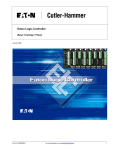
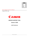
PanelMate Omron Communication Driver Manual Eaton Corporation Cutler-Hammer Business Unit 811 Green Crest Drive Columbus, OH 43081 Preface Information in this manual is subject to change without notice and does not represent a commitment on the part of Eaton’s Cutler-Hammer, Inc. Permission is granted to duplicate this material without modification only for your use or the internal use of other members of your company or your agents to assist you in the use and servicing of products purchased from Eaton’s Cutler-Hammer. No permission is granted to modify this material or include this material in a compilation. RESTRICTED RIGHTS LEGEND Use, duplication, or disclosure by the Government is subject to restrictions set forth in paragraph (b)(3)(B) of the Rights in Technical Data and Computer Software clause of DAR 7-104.9(a). Contractor/Manufacturer is Eaton Corporation’s Cutler-Hammer Business Unit, 811 Green Crest Drive, Columbus, OH 43081. TRADEMARKS PanelMate is a federally registered trademark of Eaton Corporation. MS-DOS, Microsoft, and Windows are federally registered trademarks of Microsoft Corporation. Data Highway and Data Highway Plus are trademarks of Allen-Bradley. DeviceNet is a trademark of Open DeviceNet Vendor Association. Iomega is a federally registered trademark of Iomega Corporation. Commercial brand names (trademarks) of products of manufacturers or developers, other than Eaton Corporation or its affiliates, that appear in this manual may be registered or unregistered trademarks of those respective manufacturers or developers, which have expressed neither approval nor disapproval of Cutler-Hammer products and services. 2002 Eaton Corporation. All rights reserved. Printed in the United States of America. P/N 01-00455-02 2 Omron Communication Driver Manual Support Services The goal of Eaton’s Cutler-Hammer business unit is to ensure your greatest possible satisfaction with the operation of our products. We are dedicated to providing fast, friendly and accurate assistance. That is why we offer you so many ways to get the support you need. Whether it's by phone, fax or mail, you can access Eaton’s Cutler-Hammer support information 24 hours a day, seven days a week. Our wide range of services are listed below. You should contact your local distributor for product pricing, availability, ordering, expediting and repairs. Website Address www.cutler-hammer.eaton.com Use the Cutler-Hammer website to find product information. You can also find information on local distributors or Cutler-Hammer sales offices. e-TRC Technical Resource Center (support for OI, PLC & IPC) VOICE: • 800-809-2772, selection 5 (8:00AM-5:00PM EST) • 414-449-7100, selection 5 (8:00AM-5:00PM EST) FAX: 614-882-0417 EMAIL: [email protected] AFTER-HOURS PLANT DOWN EMERGENCY: • 800-809-2772, selection 5 (5:00PM-8:00AM EST) • 414-449-7100, selection 5 (5:00PM-8:00AM EST) If you are in the US or Canada, and have OI/PLC/IPC questions, you can take advantage of our tollfree line for technical assistance with hardware and software product selection, system design and installation, and system debugging and diagnostics. Technical support engineers are available for calls during regular business hours. Information Fax-Back Service VOICE: 614-899-5323 The latest Cutler-Hammer product information, specifications, technical notes and company news are available to you via fax through this direct document request service. Using a touch-tone phone, you can select any of the info faxes from our automated product literature and technical document library, enter a fax number and receive the information immediately. Repair and Upgrade Service (support for OI & IPC) VOICE: • 800-809-2772, selection 5 (8:00AM-5:00PM EST) • 414-449-7100, selection 5 (8:00AM-5:00PM EST) FAX: 614-882-3414 EMAIL: [email protected] If you have questions regarding the repair or upgrade of an OI/IPC, contact your local distributor. Additional support is also available from our well-equipped Repair and Upgrade Service department. European PanelMate Support Center VOICE: +41 1 806 64 44 (9:00AM-5:00PM CET) EMAIL: [email protected] This center, located in Zurich, Switzerland, provides high-level quality support and product repair services for your PanelMate products. You will receive real-time technical and application support. Table of Contents 3 Table of Contents Introduction....................................................................................................................................... 5 Introduction .................................................................................................................................... 6 Installing Drivers ............................................................................................................................ 6 Downloading Drivers to a PanelMate Unit..................................................................................... 7 Serial Transfer Cables ................................................................................................................ 7 Memory Types................................................................................................................................ 9 Possible Configurations .................................................................................................................. 10 Direct Connection......................................................................................................................... 11 Network Connection..................................................................................................................... 12 Cabling............................................................................................................................................. 13 Cable Configurations .................................................................................................................... 14 RS232C Cabling for the Omron C Series................................................................................. 14 RS232C Cabling for the Omron CV Series.............................................................................. 14 RS422 Cabling for the Omron C Series ................................................................................... 15 RS422 Cabling for the Omron CV Series ................................................................................ 15 RS232C Cabling for the Omron C Series................................................................................. 16 RS232C Cabling for the Omron CV Series.............................................................................. 16 RS422 Cabling for the Omron C Series ................................................................................... 17 RS422 Cabling for the Omron CV Series ................................................................................ 17 RS232C Cabling for the Omron CQ and CS Series ................................................................. 18 RS232C Cabling for the Omron CQ and CS Series ................................................................. 18 Communication Parameters .......................................................................................................... 19 Default Communications Parameters ........................................................................................... 20 Communication Module ............................................................................................................... 21 C200H-LK201-P Module......................................................................................................... 21 Settings for SW1, SW2, SW3 and SW4................................................................................... 22 C200H-LK01 Communication Module (Rear View) ............................................................... 23 CS/CQ System Parameters ....................................................................................................... 24 Word and Bit References ............................................................................................................... 27 Word Referencing Method ........................................................................................................... 28 Memory Types Supported by the CS_CV Series Model Family.................................................. 29 CIO Area .................................................................................................................................. 29 Holding Area ............................................................................................................................ 30 Timer Present Value Area ........................................................................................................ 30 Counter Present Value Area ..................................................................................................... 30 Timer/Counter Present Value Area .......................................................................................... 31 Data Memory Area ................................................................................................................... 31 Auxiliary Area.......................................................................................................................... 32 Extended Memory Area ........................................................................................................... 32 Extended Memory Area – Specified Bank ............................................................................... 33 Memory Types Supported by the CQ_C Series Model Family .................................................... 34 Internal Relay Area .................................................................................................................. 34 Link Relay Area ....................................................................................................................... 35 Holding Relay Area.................................................................................................................. 35 4 Omron Communication Driver Manual Timer/Counter Present Value Area .......................................................................................... 36 Data Memory Area ................................................................................................................... 36 Auxiliary Relay Area................................................................................................................ 37 Extended Memory Area – Current Bank .................................................................................. 37 Extended Memory Area – Specified Bank ............................................................................... 38 Index.................................................................................................................................................39 Chapter 1: Introduction Introduction 1 In this chapter, you will learn: • How to install driver software • How to download drivers to a PanelMate unit • The supported memory types 5 6 Omron Communication Driver Manual Introduction The Operator Station can be used with the programmable controllers in the Omron C Series (C20K, C28K, C40K, C60K, C20, C20H, C28H, C40H, C200H, C120, C500, C1000H, and C2000H), the CV Series (CV400 and CV1000), the CS1 Series (CS1G, CS1H) and the CQM Series (CQM1). Note: Check the Cutler-Hammer web site for current information on PanelMate PC connectivity to the Omron driver. Installing Drivers PanelMate Configuration Editor software is installed using a CD-ROM. To install the drivers from the CD-ROM, select the Install Software option and then Install Drivers. From the dialog box, select the driver you wish to install. Chapter 1: Introduction 7 Downloading Drivers to a PanelMate Unit • In the VCP Transfer Utility, choose the “Executive” tab and select the proper Executive Firmware to download to the PanelMate unit. • Click the button labeled “Add to Operation List.” Note: In order to download to a PanelMate for the first time or to clear the existence of another driver, the PanelMate must first be loaded with Executive Firmware. • Choose the “Driver” tab. • Select the appropriate driver to be downloaded to the PanelMate. • Click the button labeled “Add to Operation List.” • Place the PanelMate unit in Serial Transfer Mode. • Connect a serial transfer cable from the correct port on the PC to port 1 on the PanelMate. (See cabling below.) • Click “Start” at the bottom of the VCP Transfer Utility window. • Note: For a more detailed description of downloading procedures and troubleshooting see PanelMate Power Series, PowerPro, Pro LT Transfer Utility User’s Guide. Serial Transfer Cables Cable P/N 0518 8 Omron Communication Driver Manual Cable P/N 0818 (PanelMate Power Series 1500 and PanelMate 500 only) Chapter 1: Introduction 9 Memory Types The following list contains the memory types supported by the Omron CQ_C Series driver. IR I/O and Internal Relay HR Holding Relay TC Timer/Counter DM Data Memory LR Link Relay AR Auxiliary Relay EM Extended Memory The following list contains the memory types supported by the Omron CS_CV Series driver. CIO I/O and Internal Relay A Auxiliary Relay T Timer D Data Memory H Holding Area C Counter E Extended Memory The Open Host Link protocol (C-mode and CV-mode) is common to all Omron PLCs. Host Link protocol does not directly support bit writes, although the protocol will allow devices to force bits on and off. The Omron driver has been implemented to force bits on and off. At power up, the ladder logic in the PLC should write zeroes to all of the bit areas addressed by the Operator Station for control buttons. This will ensure that in the event that power is lost to the PLC during the time a control button is pressed, all of the bit areas are returned to a zero state. The IR and LR memory types are not retentive except for the C200H. After power is lost, control over these areas returns to the PLC ladder logic program. The C200H processor is different from all of the other C and CV CPUs because it has the ability to set whether or not these bit areas are retentive. The C200H should be set up to be non-retentive for these bit areas. A bit in the special relay memory determines whether or not the memory is retentive. The Operator Station cannot write to special relay memory. You must use your programmer to access special relay memory. Note: Omron markets the P series models (C20P, C28P, C40P, and C60P) and the F series models (C120F and C500F) overseas. The P series can be configured like the K series models (C20K, C28K, C40K, and C60K) and the F series can be configured like the C120 and C500 models. 10 Omron Communication Driver Manual Possible Configurations 2 In this chapter, you will learn: • How to connect an operator station to Omron PLCs Chapter 2: Possible Configurations Direct Connection The figures below show a direct connection between the Operator Station and the processor. 11 12 Omron Communication Driver Manual Network Connection The following figure shows a network consisting of three PLCs and an Operator Station. Chapter 3: Cabling Cabling 3 In this chapter, you will learn: • The cabling requirements for Omron PLCs 13 14 Omron Communication Driver Manual Cable Configurations The following tables show the pinouts for the Omron C Series, CV Series, CQ Series, and CS Series PLCs. The Omron driver supports RS232C and RS422 communications. The maximum cable length when using RS232 is 50 feet, while the maximum cable length for RS422 is 4000 feet. RS422 cable must be a twisted double-wire shielded cable. A 15-foot PLC cable can be purchased from Cutler-Hammer. Contact the Customer Support Group (listed under Support Services in the Preface) or your local distributor for more information. Cabling catalog numbers are listed with the tables below. They are also listed in the PLC Cabling CrossReference List section in Appendix A. RS232C Cabling for the Omron C Series Cable Catalog Number: OM21 for all PanelMate Power Series and Power Pro Models The Operator Stations that have 9-pin female connectors (DB-9S) must have cables configured with male connectors (DB-9P). RS232C Cabling for the Omron CV Series Cable Catalog Number: OM22 for all PanelMate Power Series and Power Pro Models The Operator Stations that have 9-pin female connectors (DB-9S) must have cables configured with male connectors (DB-9P). Chapter 3: Cabling 15 RS422 Cabling for the Omron C Series Cable Catalog Number: OM23A for all PanelMate Power Series and Power Pro Models The Operator Stations that have 9-pin female connectors (DB-9S) must have cables configured with male connectors (DB-9P). RS422 Cabling for the Omron CV Series Cable Catalog Number: OM24A for all PanelMate Power Series and Power Pro Models The Operator Stations that have 9-pin female connectors (DB-9S) must have cables configured with male connectors (DB-9P). 16 Omron Communication Driver Manual RS232C Cabling for the Omron C Series Cable Catalog Number: OM21 for all PanelMate Power Series and Power Pro Models The Operator Stations that have RJ-11 6-wire modular jacks must have cables configured with male modular connectors. RS232C Cabling for the Omron CV Series Cable Catalog Number: OM22 for all PanelMate Power Series and Power Pro Models The Operator Stations that have RJ-11 6-wire modular jacks must have cables configured with male modular connectors. Chapter 3: Cabling 17 RS422 Cabling for the Omron C Series Cable Catalog Number: OM23A for all PanelMate Power Series and Power Pro Models The Operator Stations that have RJ-45 modular jacks must have cables configured with male modular connectors. RS422 Cabling for the Omron CV Series Cable Catalog Number: OM24A for all PanelMate Power Series and Power Pro Models The Operator Stations that have RJ-45 modular jacks must have cables configured with male modular connectors. 18 Omron Communication Driver Manual RS232C Cabling for the Omron CQ and CS Series The Operator Stations that have 9-pin female connectors (DB-9S) must have cables configured with male connectors (DB-9P). For proper communication, the following parameters must be observed: • Use Omron HostLink driver • Communication parameters are 7 data bits, 2 stop bits, even parity, 9600 or 19200 baud rate, RS232 electrical Operator Station Omron CQ & CS Series PLCs 9-pin (male) 9-pin (male) RX 2 2 TX TX 3 3 RX GND 5 9 GND 4 5 RS232C Cabling for the Omron CQ and CS Series The Operator Stations that have RJ-11 6-wire modular jacks must have cables configured with male modular connectors. Operator Station Omron CQ & CS Series PLCs RJ11 6-wire (male) 9-pin (male) RX 3 2 TX TX 5 3 RX GND 1 9 GND 4 5 Chapter 4: Communications Parameters Communication Parameters 4 In this chapter, you will learn: • The different switch settings 19 20 Omron Communication Driver Manual Default Communications Parameters The Open Host Link Protocol supports both point-to-point and network interfaces. Both rack-mounted and CPU-mounted Host Link protocol interface links support RS232 and RS422 communication. The default communications parameters are shown below. Baud rate 300 to 19200 Data bits 7 Parity Even Stop bits 2 The Omron PLC ID must be set in the range 00-31 for communications. Note: The settings for parameters, such as baud rate, must match the parameters set for the Operator Station. Chapter 4: Communications Parameters Communication Module C200H-LK201-P Module The C200H-LK201-P communication module is an interface between the Operator Station and the Omron PLC. If you have another communication module, refer to your PLC user manual for more information. Note: A switch of the same name sometimes has different functions on different units. 21 22 Omron Communication Driver Manual Settings for SW1, SW2, SW3 and SW4 SW1 and SW2 set the unit number. Set SW1 to the number for the tens digit in the unit number and set SW2 to the ones digit in the node or unit number. For configuration information for SW3 and SW4, refer to the tables below. Settings for SW3 0 300 bps 1 600 bps 2 1200 bps 3 2400 bps 4 4800 bps 5 9600 bps 6 19200 bps 7 Do not set 8 Do not set 9 Do not set The Operator Station supports all three command levels (1 through 3) of Host Link Unit commands. Settings for SW4 SW4 Command Level 0 1 1 1, 2 2 1, 2, 3 3 Do not set 4 1 5 1, 2 6 1, 2, 3 7 Do not set 8 1 9 1, 2 A 1, 2, 3 B Do not set C 1 D 1, 2 E 1, 2, 3 F Do not set Parity Transmission Code Even ASCII 7 bit 2 Stop bits Odd Even JIS 8 bits 1 Stop bit Odd Chapter 4: Communications Parameters 23 C200H-LK01 Communication Module (Rear View) The C200H-LK201 communication module has four dipswitches and a selector switch located on the back of the module. Dipswitches 1 and 2 are not used and should be set to OFF. Dipswitches 3 configures the module for a single-link or multiple-link and should be set to ON to communicate to the Operator Station. Dipswitch 4 configures the 5 V power supply and you should set as necessary for your application. The CTS Selector Switch must be set to 0V to communicate to the Operator Station. 24 Omron Communication Driver Manual CS/CQ System Parameters The following screens detail the CS/CQ system parameters in the PanelMate software. Chapter 4: Communications Parameters Settings in the Omron Software Set to match the PanelMate PLC Name and Port Table are shown below. 25 26 Omron Communication Driver Manual Chapter 5: Word and Bit References Word and Bit References 5 In this chapter, you will learn: • How to configure word and bit references 27 28 Omron Communication Driver Manual Word Referencing Method The general word referencing method is: [plcname,word#format] The "plcname" is the name of the designated PLC as listed in the PLC Name and Port Table. The "word" is the reference number (address) of the word or register to be read or written. The "#format" is a code which specifies the format of the data being read or written. The "plcname" and "#format" are optional if you are using the default PLC and do not wish to change the data format, respectively. The general bit referencing method is: [plcname,bit] The "plcname" is the designated PLC as listed in the PLC Name and Port Table. The "bit" is the reference number (address) of the bit, coil, or input to be written or read. See the "Word and Bit References" topic in the Configuration Software Online Help for a more detailed explanation of word and bit references, including format descriptions. The Omron Host Link protocol is supported on the Operator Station for models C20K, C28K, C40K, C60K, C20, C20H, C28H, C40H, C200H, C120, C500, C1000H, C2000H, CV500, CV1000, CQM1, and CS1. These models use decimal register addresses. Bit references are from 0 to 15. The Operator Station’s format default is S16. Note that the PLC reference consists of one-, two- and three-character prefixes that identify the memory type being referenced followed by the specific address. Note: The use of the memory type code is optional for CIO Area access. In the event a memory type code is not specified, the standard memory type code “CIO” will be assumed. The following is the format of a register reference. [plcname, wwnnn] plcname Optional PLC name found in the PLC Name Table. If left blank, the default name is used. , Optional PLC name delimiter. ww The word device memory type. nnnn The word number; maximum of 4 characters; leading zeroes are allowed. The following is the format of a register bit reference. [plcname, wwnnn.bb] plcname Optional PLC name found in the PLC Name Table. If left blank, the default name is used. , Optional PLC name delimiter. ww The word device memory type. nnnn The word number; maximum of 4 characters; leading zeroes are allowed. . Bit delimiter character. bb Bit number in the range 00-15; leading zeroes are allowed. The Operator Station will allow the Omron models a maximum of 29 contiguous words for each block read. The maximum number of unused words before another read is generated is 15. Chapter 5: Word and Bit References 29 Memory Types Supported by the CS_CV Series Model Family The CS-CV Model Family will support the memory types identified in this section. The address syntax for each memory type is described here but the individual PLC controller’s capabilities actually defines the valid address ranges within each of the memory types. Reference syntax checking performed by the parser will verify compliance with the addressing scheme of the model family and with the Open Host Link Protocol but will not validate the existence of the reference in the memory range of the specific PLC model. If the access mode of a specific memory type supports write operations, the parser will consider the entire range of that memory type as being accessible for read/write operations for that mode. The specific memory type access modes that do not support write operations have been indicated. CIO Area Word Access Syntax CIOxxxx where: CIO xxxx = Memory type code for CIO Area references = Specified word (0-9999) leading 0s not required Bit Access Syntax CIOxxxx.yy where: CIO = Memory type code for CIO Area references xxxx = Specified word (0-9999) leading 0s not required yy = Specified bit (0-15) leading 0s not required Alternate Memory Type Codes Note: The use of the memory type code is optional for CIO Area access. In the event a memory type code is not specified, the standard memory type code “CIO” will be assumed. The alternate memory type codes that can be used to access the CIO Area references are ‘IR’ and ‘SR’. Note that in the event a communication error occurs when accessing a reference using the alternate memory type code, the communications error displayed will be mapped to the standard memory type code ‘CIO’ and not the alternate code. 30 Omron Communication Driver Manual Holding Area Word Access Syntax Hxxxx where: H = Memory type code for Holding Area references xxxx = Specified word (0-9999) leading 0s not required Bit Access Syntax Hxxxx, yy where: H = Memory type code for Holding Area references xxxx = Specified word (0-9999) leading 0s not required yy = Specified bit (0-15) leading 0s not required Alternate Memory Type Codes The alternate memory type code that can be used to access the Holding Area reference is ‘HR’. Note that in the event a communication error occurs when accessing a reference using the lternate memory type code, the communications error displayed will be mapped to the standard memory type code ‘H’ and not the alternate code. Timer Present Value Area Word Access Syntax Txxxx where: T = Memory type code for Timer PV Area references xxxx = Specified word (0-2047) leading 0s not required Bit Access Syntax Txxxx, yy where: T = Memory type code for Timer PV Area references xxxx = Specified word (0-2047) leading 0s not required yy = Specified bit (0-15) leading 0s not required The operation of writing bits in Timer Present Value Area references is not supported. Counter Present Value Area Word Access Syntax Cxxxx where: C = Memory type code for Counter PV Area references xxxx = Specified word (0-2047) leading 0s not required Bit Access Syntax Cxxxx, yy where: C = Memory type code for Counter PV Area references xxxx = Specified word (0-2047) leading 0s not required yy = Specified bit (0-15) leading 0s not required The operation of writing bits in Counter Present Value Area references is not supported. Chapter 5: Word and Bit References 31 Timer/Counter Present Value Area Note that TC memory type code is being supported to provide backwards compatibility to existing PanelMate applications. The TC memory type code can be used to access both the Timer and Counter Present Value Areas. The following are examples of the TC equivalent to the T or C reference: T0000 = TC0000 T2047 = TC2047 C0000 = TC2048 C2047 = TC4095 Word Access Syntax TCxxxx where: TC = Memory type code for Timer/Counter PV Area references xxxx = Specified word (0-9999) leading 0s not required The operation of writing words to the Timer/Counter Present Value Area is not supported. Bit Access Syntax TCxxxx, yy where: TC = Memory type code for Timer/Counter PV Area references xxxx = Specified word (0-9999) leading 0s not required yy = Specified bit (0-15) leading 0s not required The operation of writing bits in Timer/Counter Present Value Area references is not supported. Data Memory Area Word Access Syntax Dxxxx where: D = Memory type code for Data Memory Area references xxxx = Specified word (0-9999) leading 0s not required The operation of writing words to the Timer/Counter Present Value Area is not supported. Bit Access Syntax Dxxxx, yy where: D = Memory type code for Data Memory Area references xxxx = Specified word (0-9999) leading 0s not required yy = Specified bit (0-15) leading 0s not required The operation of writing bits in Data Memory Area references is not supported. Alternate Memory Type Codes The alternate memory type code that can be used to access the Data Memory Area reference is ‘DM’. Note that in the event a communication error occurs when accessing a reference using the alternate memory type code, the communications error displayed will be mapped to the standard memory type code ‘D’ and not the alternate code. 32 Omron Communication Driver Manual Auxiliary Area Word Access Syntax Axxxx where: A = Memory type code for Auxiliary Area references xxxx = Specified word (0-9999) leading 0s not required The operation of writing words to the Auxiliary Area is not supported. Bit Access Syntax Axxxx, yy where: A = Memory type code for Auxiliary Area references xxxx = Specified word (0-9999) leading 0s not required yy = Specified bit (0-15) leading 0s not required The operation of writing bits in Auxiliary Area references is not supported. Alternate Memory Type Codes The alternate memory type code that can be used to access the Data Memory Area reference is ‘AR’. Note that in the event a communication error occurs when accessing a reference using the alternate memory type code, the communications error displayed will be mapped to the standard memory type code ‘A’ and not the alternate code. Extended Memory Area Word Access Syntax Exxxx where: E = Memory type code for Extended Memory Area references xxxx = Specified word (0-9999) leading 0s not required Bit Access Syntax Exxxx, yy where: E = Memory type code for Extended Memory Area references xxxx = Specified word (0-9999) leading 0s not required yy = Specified bit (0-15) leading 0s not required The operation of writing bits in Extended Memory Area references is not supported. Alternate Memory Type Codes The alternate memory type code that can be used to access the Extended Memory Area reference is ‘EM’. Note that in the event a communication error occurs when accessing a reference using the alternate memory type code, the communications error displayed will be mapped to the standard memory type code ‘E’ and not the alternate code. Chapter 5: Word and Bit References Extended Memory Area – Specified Bank Word Access withing a Specified Bank Syntax Eh_xxxx where: E = Memory type code for Extended Memory Area references h = Specified bank (0-F hex) xxxx = Specified word (0-9999) leading 0s not required Bit Access within a Specified Bank Syntax Eh_xxxx, yy where: E = Memory type code for Extended Memory Area references h = Specified bank (0-F hex) xxxx = Specified word (0-9999) leading 0s not required yy = Specified bit (0-15) leading 0s not required The operation of writing bits in Extended Memory Area references is not supported. 33 34 Omron Communication Driver Manual Memory Types Supported by the CQ_C Series Model Family The CQ-C Model Family will support the memory types identified in this section. The address syntax for each memory type is described here but the individual PLC controller’s capabilities actually defines the valid address ranges within each of the memory types. Reference syntax checking performed by the parser will verify compliance with the addressing scheme of the model family and with the Open Host Link Protocol but will not validate the existence of the reference in the memory range of the specific PLC model. If the access mode of a specific memory type supports write operations, the parser will consider the entire range of that memory type as being accessible for read/write operations for that mode. The specific memory type access modes that do not support write operations have been indicated. Internal Relay Area Word Access Syntax IRxxxx where: IR = Memory type code for Internal Relay Area references xxxx = Specified word (0-9999) leading 0s not required Bit Access Syntax Rxxxx.yy where: IR = Memory type code for Internal Relay Area references xxxx = Specified word (0-9999) leading 0s not required yy = Specified bit (0-15) leading 0s not required Alternate Memory Type Codes Note: The use of the memory type code is optional for Internal Relay Area access. In the event a memory type code is not specified, the standard memory type code “IR” will be assumed. The alternate memory type codes that can be used to access the Internal Relay Area references are ‘IR’ and ‘SR’. Note that in the event a communication error occurs when accessing a reference using the alternate memory type code, the communications error displayed will be mapped to the standard memory type code ‘CIO’ and not the alternate code. Chapter 5: Word and Bit References 35 Link Relay Area Word Access Syntax LRxxxx where: LR = Memory type code for Link Relay Area references xxxx = Specified word (0-9999) leading 0s not required Bit Access Syntax LRxxxx, yy where: LR = Memory type code for Link Relay Area references xxxx = Specified word (0-9999) leading 0s not required yy = Specified bit (0-15) leading 0s not required The operation of writing bits in Link Relay Area references is not supported. Alternate Memory Type Codes The alternate memory type code that can be used to access the Link Relay Area reference is ‘L’. Note that in the event a communication error occurs when accessing a reference using the lternate memory type code, the communications error displayed will be mapped to the standard memory type code ‘LR’ and not the alternate code. Holding Relay Area Word Access Syntax HRxxxx where: HR = Memory type code for Holding Relay Area references xxxx = Specified word (0-9999) leading 0s not required Bit Access Syntax HRxxxx, yy where: HR = Memory type code for Holding Relay Area references xxxx = Specified word (0-9999) leading 0s not required yy = Specified bit (0-15) leading 0s not required Alternate Memory Type Codes The alternate memory type code that can be used to access the Holding Relay Area reference is ‘H’. Note that in the event a communication error occurs when accessing a reference using the alternate memory type code, the communications error displayed will be mapped to the standard memory type code ‘HR’ and not the alternate code. 36 Omron Communication Driver Manual Timer/Counter Present Value Area Word Access Syntax TCxxxx where: TC = Memory type code for Timer/Counter PV Area references xxxx = Specified word (0-9999) leading 0s not required Bit Access Syntax TCxxxx, yy where: TC = Memory type code for Timer/Counter PV Area references xxxx = Specified word (0-9999) leading 0s not required yy = Specified bit (0-15) leading 0s not required The operation of writing bits in Timer/Counter Present Value Area references is not supported. Data Memory Area Word Access Syntax DMxxxx where: DM = Memory type code for Data Memory Area references xxxx = Specified word (0-9999) leading 0s not required Bit Access Syntax DMxxxx, yy where: DM = Memory type code for Data Memory Area references xxxx = Specified word (0-9999) leading 0s not required yy = Specified bit (0-15) leading 0s not required The operation of writing bits in Data Memory Area references is not supported. Alternate Memory Type Codes The alternate memory type code that can be used to access the Data Memory Area reference is ‘D’. Note that in the event a communication error occurs when accessing a reference using the alternate memory type code, the communications error displayed will be mapped to the standard memory type code ‘DM’ and not the alternate code. Chapter 5: Word and Bit References 37 Auxiliary Relay Area Word Access Syntax ARxxxx where: AR = Memory type code for Auxiliary Relay Area references xxxx = Specified word (0-9999) leading 0s not required The operation of writing words to the Auxiliary Relay Area is not supported. Bit Access Syntax ARxxxx, yy where: AR = Memory type code for Auxiliary Relay Area references xxxx = Specified word (0-9999) leading 0s not required yy = Specified bit (0-15) leading 0s not required The operation of writing bits in Auxiliary Relay Area references is not supported. Alternate Memory Type Codes The alternate memory type code that can be used to access the Auxiliary Relay Area reference is ‘A’. Note that in the event a communication error occurs when accessing a reference using the alternate memory type code, the communications error displayed will be mapped to the standard memory type code ‘AR’ and not the alternate code. Extended Memory Area – Current Bank Word Access Syntax EMxxxx where: EM = Memory type code for Extended Memory Area references xxxx = Specified word (0-9999) leading 0s not required Bit Access Syntax EMxxxx, yy where: EM = Memory type code for Extended Memory Area references xxxx = Specified word (0-9999) leading 0s not required yy = Specified bit (0-15) leading 0s not required The operation of writing bits in Extended Memory Area references is not supported. Alternate Memory Type Codes The alternate memory type code that can be used to access the Extended Memory Area reference is ‘E’. Note that in the event a communication error occurs when accessing a reference using the alternate memory type code, the communications error displayed will be mapped to the standard memory type code ‘EM’ and not the alternate code. 38 Omron Communication Driver Manual Extended Memory Area – Specified Bank Word Access within a Specified Bank Syntax Eh_xxxx where: E = Memory type code for Extended Memory Area references h = Specified bank (0-F hex) xxxx = Specified word (0-9999) leading 0s not required Bit Access within a Specified Bank Syntax Eh_xxxx, yy where: E = Memory type code for Extended Memory Area references h = Specified bank (0-F hex) xxxx = Specified word (0-9999) leading 0s not required yy = Specified bit (0-15) leading 0s not required The operation of writing bits in Extended Memory Area references is not supported. Index Index C C200H-LK01 Communication Module, 23 Cable Configurations, 14 Communication Module, 21 CS/CQ System Parameters, 24 D Default Communications Parameters, 20 Direct Connection, 11 Downloading Drivers to a PanelMate Unit, 7 N Network Connection, 12 R RS232 Cabling for the Omron C Series, 14 RS232C Cabling for the Omron C Series, 16 RS232C Cabling for the Omron CV Series, 14, 16, 18 RS422 Cabling for the Omron C Series, 15, 17 RS422 Cabling for the Omron CV Series, 15, 17 S I Installing Drivers, 6 Introduction, 6 M Memory Types, 9 Omron C Series, 9 Omron CV Series, 9 Serial Transfer Cables, 7 Settings for SW1, 22 Settings for SW2, 22 Settings for SW3, 22 Settings for SW4, 22 W Word Referencing Methods, 28 39 Reader Comment Card Cutler-Hammer strives to provide quality user guides and product manuals. Please take a moment to fill out this comment card. Title: Omron Communication Driver Manual 01-00455-02 Excellent Good Is the document easy to follow? Does the product work as described in this document? Are the instructions easy to follow? Are the examples helpful/useful? Are there enough examples? Is the document organized logically? Is it easy to find what you are looking for? Are the illustrations clear and useful? How would you improve this document? Please list any errors found in this document: Other comments: Your name and address: (optional) Thank you for your comments. Please fax this page to: Cutler-Hammer Technical Publications Dept. Fax: 614-882-0417 Fair Poor