1
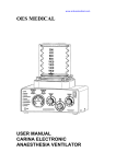
www.ardusmedical.com
OES MEDICAL LTD
UNIT 10, AREA D, RADLEY ROAD INDUSTRIAL ESTATE
RADLEY ROAD, ABINGDON OXON. OX14 3RY UK
Tel. 01235 539618 Fax 01235 539619
e-mail : [email protected]
INSTRUCTIONS FOR USE
ORION PNEUMATIC VENTILATOR
Copyright © 2001 OES Medical Ltd
Doc. 1988-501
Issue A
Page 2 of 24
INDEX
CONTENTS
PAGE NO
Index
Service and repairs
User Responsibilities
Warnings and cautions
Purpose
Description :
Front panel - description
Front panel - illustration
Rear panel - description
Rear panel - illustration
Adult bellows assembly - description
Adult bellows assembly - illustration
Ventilation cycle - description
Pneumatic circuit - description
Specification
Ventilator standard parts
Ventilator set up procedure
Pre-use function test
Clinical operation
Fault finding
User maintenance service schedule
Cleaning of the control unit
Cleaning and sterilisation of the bellows
unit
Ordering information
Disposal
2
3
4
4
5
5
7
8
10
11
12
13
14
15
16
17
18
19
20
21
21
21
22
23
NOTE :
This symbol appears on the shortform instruction label of
the ORION Ventilator.
It’s intended meaning is to refer the user to this manual.
Doc. 1988-501
Issue A
Page 3 of 24
SERVICING AND REPAIRS
In order to achieve the full operational life of the ORION ANAESTHESIA
VENTILATOR the following service schedule must be adhered to :(a) Three monthly inspection and service check.
(b) Six monthly bellows replacement.
(c) Two yearly replacement of exhaust diaphragm.
(d) Five yearly overhaul.
Service requirements are detailed in the service manual that is available to
factory trained personnel.
Further details are available from :The Service department,
OES MEDICAL LTD
UNIT 10, AREA D,
RADLEY ROAD INDUSTRIAL ESTATE,
ABINGDON,
OXFORDSHIRE,
OX14 3RY,
ENGLAND.
Phone 01235 539618
Fax 01235 539619
Always provide the following information
with any communication:(a) Type of product and part number.
(b) Product name.
(c) Serial number.
(d) Date of purchase.
(e) details of suspected fault.
Doc. 1988-501
Issue A
Page 4 of 24
USER RESPONSIBILITIES
It is the responsibility of the user of the Orion Ventilator to install, use and
maintain it according to the instructions in this manual. OES Medical Ltd is not
liable for any consequences arising from the use of the Orion Ventilator outside
the prescribed conditions, including use by under-qualified personnel.
WARNINGS AND CAUTIONS
Throughout this manual warnings and cautions relating to various aspects of use
of this ventilator are given.
WARNING
A warning indicates that there is a possible hazard to the patient, user or
environment. It is enclosed in a box to draw the reader’s attention and MUST
BE HEEDED.
CAUTION
A caution indicates that there may be a risk of damage to equipment. It is
advisable to follow the instructions given in the caution.
NOTE
Notes may appear throughout the text of this manual to indicate useful points to
the user.
It is the responsibility of the user to read this manual and fully understand the
functions of this ventilator prior to use.
Doc. 1988-501
Issue A
Page 5 of 24
PURPOSE
The OES ORION VENTILATOR is a pneumatically controlled oxygen driven
anaesthesia ventilator with bellows unit, designed for mechanical ventilation
during anaesthesia.
It can be used in closed circuit anaesthesia and to drive a Bain circuit.
The Orion Ventilator must only be used by suitably qualified personnel, for the
above purpose.
DESCRIPTION
The OES ORION VENTILATOR is a time cycled flow generator type
ventilator that is oxygen driven and is provided with an ascending bellows unit
which is easily detachable for cleaning.
FRONT PANEL - DESCRIPTION
(1) On/Off switch - rotates 90 degrees clockwise to turn the ventilator on.
(2) Manometer - calibrated between -20 to +100 cm H2O, the gauge must be
connected to the inspiratory limb of the breathing circuit via the connector on
the rear panel.
(3) Adjustable pressure relief valve - calibrated at 20 cm H2O, at 0.5 litres per
second flow. Note - the pressure relief valve will relieve at a slightly lower or
higher level depending on the flow rate selected on the flow control knob.
WARNING
The pressure relief valve is not intend for use as a pressure limiter but as a
pressure relief valve.
(4) Inspiratory time control knob - calibrated between 0.25 and 3.0 seconds,
accuracy the greater of ±10% or 0.05 seconds.
Rotation of the knurled knob clockwise increases the inspiratory time.
(5) Expiratory time control knob - calibrated between 0.5 and 6.0 seconds,
accuracy ±10%.
Rotation of the knob in a clockwise direction increases the expiratory time.
Doc. 1988-501
Issue A
Page 6 of 24
Breaths per minute is determined in the following way :B.P.M =
60
Inspiratory time + Expiratory time
The I:E ratio is determined in the following way :I:E RATIO = INSPIRATORY TIME
EXPIRATORY TIME
(6) Flow control knob - calibrated between 0.1 and 1.0 litres per second,
accuracy ±10%.
Rotation of the grooved knob in an anti clockwise direction increases the flow
rate.
The tidal volume delivered to the patient is determined in the following way :Tidal volume = inspiratory time x flow rate
(litres)
(seconds)
( litres per second)
Minimum tidal volume is 0.035 litres, maximum deliverable is 1.6 litres
because of the bellows capacity.
(7) Bellows unit assembly - the bellows canister is marked with a scale which
allows the tidal volume to the patient to be determined with bellows movement.
Further information on the bellows unit assembly are given on page 12 and 25.
Doc. 1988-501
Issue A
Page 7 of 24
Doc. 1988-501
Issue A
Page 8 of 24
REAR PANEL- DESCRIPTION
(1) High pressure oxygen inlet connector - a 1.5 metre long high pressure hose
is supplied for connection to the DISS oxygen inlet connector.
(2) Driving gas connector - a 17 mm male taper which connects to the bellows
drive gas connector with a flexible corrugated tube. (shown in the illustration)
(3) Drive gas exhaust port - the exhaust port which allows the drive gas to be
exhausted from within the bellows canister (the outside of the bellows) as the
bellows rise during the expiratory phase.
This function is controlled by a silicone diaphragm which is inflated during the
inspiratory phase and deflates to allow gas flow during the expiratory phase.
WARNING
Do not attempt to block the drive gas exhaust port.
(4) Pressure relief valve exhaust port - this exhaust port allows the drive gas to
exhaust to atmosphere when the set pressure at the adjustable pressure relief
valve has been reached.
WARNING
Do not attempt to block the pressure relief exhaust port.
(5) Manometer connection - this connects to the 2.5 metres of silicone tube and
the 22 mm taper male / female sensing tee which must be placed in the
inspiratory limb of the patient breathing circuit.
(6) Bellows driving gas connector - a 17 mm taper which connects to the
ventilator bellows drive gas connector via a flexible corrugated tube.
(7) Bellows unit exhaust port - a 30 mm taper to which the anaesthetic gas
scavenge system must be connected.
WARNING
The anaesthetic gas scavenging system must not generate more than 0.5 cm H2O
negative or positive pressure.
Failure to comply with this requirement will result in positive or negative
pressure within the breathing circuit.
Doc. 1988-501
Issue A
Page 9 of 24
(8) Bellows unit patient connection - a 22 mm male taper connection which
connects to the patient circuit via 1.8 metre length of disposable corrugated
tubing.
Doc. 1988-501
Issue A
Page 10 of 24
Doc. 1988-501
Issue A
Page 11 of 24
ADULT BELLOWS ASSEMBLY - DESCRIPTION
(1) Bellows base assembly - the bellows base assembly is attached to the top of
the ventilator case and incorporates an ‘O’ seal for the bellows housing to seal
against and an ‘O’ seal to seal between the bellows base and the exhaust gas
diaphragm assembly.
An exhaust valve seat which allows the escape of exhaust gas to the bellows
exhaust port on the rear of the assembly at the end of the expiratory phase is
situated in the centre of the assembly.
WARNING
Care must be taken not to damage the exhaust valve seat.
(2) Bellows base screws - thumb screws which hold the bellows base to the top
of the ventilator case. (4 off)
(3) Exhaust diaphragm assembly - this assembly contains a diaphragm and a
sealing disc which seals on the exhaust valve seat in the bellows base during the
expiratory phase.
(4) Exhaust diaphragm assembly screws - thumb screws which hold the
diaphragm assembly onto the bellows base assembly. (3 off)
(5) Adult bellows - the bellows are attached to the bellows base assembly by the
lower convolution on the shoulder of the bellows base assembly.
(6) Adult bellows housing - the adult bellows housing is located on the bellows
base assembly by the location ring on the bellows base assembly; it is then
locked in position by twisting clockwise until the lugs are located in the bellows
base assembly.
Doc. 1988-501
Issue A
Page 12 of 24
Doc. 1988-501
Issue A
Page 13 of 24
VENTILATION CYCLE - DESCRIPTION
(1) The bellows prior to the start of the inspiratory phase is fully inflated and
retains this position due to the weight of the exhaust diaphragm valve giving a
slight back pressure within the bellows with the fresh gas flow entering the
breathing circuit.
(2) At the start of the inspiratory phase drive gas from the ventilator enters the
inside of the bellows housing and forces the bellows down driving the patient
gas within the bellows into the breathing circuit.
During the inspiratory phase the ventilator exhaust diaphragm inflates blocking
the exhaust port and the bellows exhaust diaphragm is held shut by the pressure
of the drive gas flow from the ventilator.
(3) At the start of the expiratory phase the flow of drive gas from the ventilator
ceases and the ventilator exhaust diaphragm deflates allowing the drive gas
within the bellows housing to exhaust through the ventilator drive gas exhaust
port as the bellows rise as the exhaled gas enters the bellows.
Excess exhaled gas exhausts through the bellows exhaust port into the
scavenging system.
Doc. 1988-501
Issue A
Page 14 of 24
PNEUMATIC CIRCUIT - DESCRIPTION
The pneumatic circuit consists of two pneumatic timers which control a spool
valve supplying high pressure oxygen to the flow control valve.
The oxygen inlet pressure is regulated down by a regulator which incorporates a
sintered metal filter.
As the ventilator enters the inspiratory phase the pressure at the flow control
needle activates a logic valve and causes the expiratory valve diaphragm to
inflate, blocking the ventilator drive gas exhaust port.
At the expiratory phase the diaphragm deflates as it exhausts through the logic
valve, allowing the drive gas to exhaust to atmosphere.
The pressure at the diaphragm is controlled by a low-pressure secondary
regulator.
The breathing circuit block, which is attached to the rear panel, incorporates the
exhaust diaphragm, and also an adjustable pressure relief valve which relieves if
the circuit pressure reaches the pre-set level during the inspiratory phase.
The relief valve consists of a spring loaded plunger which seals on a seat with a
silicone seal.
The relief pressure is adjusted by changing the spring loading via the knob on
the front panel.
There is no provision for sub-ambient pressure relief, as it is unlikely that the
patient would be breathing spontaneously during ventilation under anaesthesia.
Doc. 1988-501
Issue A
Page 15 of 24
SPECIFICATION
(1) Application - adult and paediatric ventilation during anaesthesia.
(2) Gas supply - oxygen at 275 to 840 kPa, recommended 400 kPa
(3) Gas supply hose - 1.5 metres of white anti-static hose fitted with a DISS
fitting.
(4) Hose end - as requested by the end user - oxygen probe to BS 5682, mini
schrader, or open (supplied as standard)
(5) Patient airway pressure gauge - 63 mm diameter aneroid pressure gauge
with -20 to +100 cm H2O, ± (2% + 2 cm H2O), zero adjustable
(6) Ventilator to bellows connection - 17 mm taper, NOT to any published
standard to avoid mis-connection
(7) Bellows to patient taper –
22 mm taper to BS EN 1281-1:1997
(8) Bellows exhaust gas taper –
30 mm taper to BS EN 1281-1:1997
(9) Inspiratory time range - 0.25 to 3.0 ± (10% or 0.05) seconds
(10) Expiratory time range - 0.5 to 6.0 ± (10% or 0.05) seconds
(11) Frequency range - 7.5 to 70 breaths per minute (derived from inspiratory
and expiratory times).
(12) Inspiratory gas flow rate - 0.1 to 1.0 ± (10% or 0.02) litre per second of
oxygen; at supply pressures below 350 kPa, flow is reduced to no less than 75%
of setting at 275 kPa (pro-rata)
(13) Tidal volume range - 0.036 to 2.025 litres per breath (derived from
inspiratory time and inspiratory flow rate).
NOTE
The maximum tidal volume which can be achieved is 1.6 litres due to the
capacity of the bellows. If it is desired to set a tidal volume, this should be done
by referring to the movement of the bellows. Small tidal volumes (less than 300
ml) should be achieved using the paediatric bellows assembly.
Doc. 1988-501
Issue A
Page 16 of 24
(14) Minute volume range - derived from tidal volume and frequency. At I:E
ratio of 1:1, minute volumes of more than 22.5 l/m can be achieved.
(15) Inspiratory relief pressure - variable between 20 and 80 cm H2O, calibrated
at 20 cm H2O and 0.5 l/sec. Maximum relief pressure is 100 cm H2O at
maximum flow rate.
(17) I:E ratio - variable between 1:18 and 4.9:1
(18) Weight - 7.7 Kg
(19) Dimensions -
height of complete ventilator
height of control unit
width
depth
- 325 mm
- 110 mm
- 260 mm
- 260 mm
(20) Sterilisation - for details on bellows assembly sterilisation see appropriate
section.
(22) Alarms - none - an airway pressure alarm is available as an optional extra.
VENTILATOR STANDARD PARTS
The ventilator is supplied with the following standard parts :(1) High pressure drive hose. (Specification as per order)
(2) Ventilator to bellows drive hose.
(3) Manometer tube.
(4) Pressure sensing tee piece. (22 mm male/female taper)
(5) Patient breathing system drive hose with male and female 22 mm taper
connectors - 1.8 metre long.
(6) User manual.
Doc. 1988-501
Issue A
Page 17 of 24
VENTILATOR SET- UP PROCEDURE
(1) Mounting the ventilator - the ventilator can be mounted either on the
anaesthetic machine shelf or on to a pole mount bracket plate (to suit diameter
25.0 / 25.4 mm poles).
The bracket plate is attached by removing the feet from the ventilator and
attaching the bracket in its place.
This plate is an optional extra - see the spares section for details.
(2) High pressure hose assembly - attach the hose to the ventilator, care must be
taken to attain a leak free seal without over tightening the fitting. Attach the
other end of the hose assembly to the high pressure oxygen supply.
NOTE
The high pressure hose assembly, when not otherwise specified, has a free end
which must be terminated with the correct connector for the machine to which it
will be attached.
(3) Ventilator to bellows drive hose - attach the corrugated hose to both the
ventilator drive gas taper and the bellows drive gas taper.
(4) Manometer tube - attach the silicone tube to the manometer connection on
the rear panel, place the pressure sensing tee piece in the inspiratory limb of the
patient breathing circuit.
(5) Patient breathing system drive hose - connect the 22 mm female taper to the
bellows breathing system taper, connect the other end to the patient circuit.
(6) Scavenging system - connect the exhaust port on the bellows unit to a
scavenging system.
WARNING
The anaesthetic gas scavenging system must not generate more than 0.5 cm
H2O of negative or positive pressure.
Failure to comply with this requirement will result in positive or negative
pressure within the breathing circuit.
Doc. 1988-501
Issue A
Page 18 of 24
PRE - USE FUNCTION TEST
(1) Ensure that the ventilator is correctly connected - refer to the ventilator set
up procedure.
(2) Set the adjustable pressure relief valve to the required setting.
(3) Set the desired inspiratory time.
(4) Set the desired expiratory time.
(5) Set the desired flow rate.
(6) Attach a 2 litre breathing bag to the patient connection as a breathing bag.
(7) Fill the bellows by using the anaesthetic machine oxygen flush.
(8) Turn the ventilator on and ensure that the ventilator delivers the correct tidal
volume - this can be checked by the scale on the adult bellows housing or by
using a flow sensor.
(9) Remove the breathing bag and occlude the end of the patient connector.
(10) Refill the bellows with the oxygen flush.
(11) Turn the ventilator back on and check that the patient circuit relieves at the
set level.
WARNING
The pressure relief valve is not intended for use as a pressure limiter but as a
pressure relief valve.
The pressure at which the circuit relieves is effected by the flow rate set at the
ventilator.
Doc. 1988-501
Issue A
Page 19 of 24
CLINICAL OPERATION
(1) Prior to use with a patient check that all connections are correct and that
there are no leaks.
(2) Perform the pre-use function test.
(3) Set the desired ventilator parameters.
WARNING
The actual ventilation of the patient may vary from the set ventilator parameters
due to compliance and circuit leaks.
The patient ventilation must be monitored independently from the ventilator.
It is the responsibility of the user to monitor patient ventilation.
NOTE
The use of this ventilator is not recommended without the use of an electronic
breathing circuit pressure monitor with appropriate alarms.
The use of this ventilator is recommended with agent and oxygen analysers.
Doc. 1988-501
Issue A
Page 20 of 24
FAULT FINDING
FAULT CONDITION
POSSIBLE CAUSE
When the ventilator is turned on it
does not cycle.
(1) The oxygen high pressure hose
is not connected.
(2) The oxygen supply is not turned
on.
Bellows will not fill, or it collapses.
(1) No fresh gas flow
(2) Breathing system hose
disconnected.
(3) Detached or damaged bellows.
(4) Damaged exhaust diaphragm
assembly.
(5) Missing or damaged ‘O’ seals.
(6) Damaged bellows base
assembly.
Bellows collapses progressively during (1) Anaesthesia machine APL valve
use, with normal fresh gas flow.
may be open.
(2) Breathing system leak.
(3) Damaged exhaust diaphragm
assembly.
(4) Missing or damaged ‘O’ seal at
exhaust diaphragm assembly.
Tidal volume is incorrect
Doc. 1988-501
(1) Missing or damaged ‘O’ seals.
(2) Damaged exhaust diaphragm
assembly.
(3) Partially detached bellows.
(4) High compliance.
(5) low oxygen inlet pressure.
Issue A
Page 21 of 24
USER MAINTENANCE
Service schedule
The ventilator must be serviced by a factory trained engineer to the following
schedule: (a) 3 monthly inspection and function check.
(b) 6 monthly bellows replacement.
(c) 2 yearly replacement of exhaust diaphragm.
(d) 5 yearly major service.
Cleaning of the ventilator control unit
The ventilator control unit must only be cleaned with a damp cloth and if
necessary with warm mild detergent to remove persistent grime.
WARNING
Do not allow the cleaning liquid to enter the control unit.
CAUTION
Do not use harsh or abrasive cleaning agents on any parts of the ventilator.
Doc. 1988-501
Issue A
Page 22 of 24
Cleaning and sterilisation of the bellows unit
To disassemble the bellows assembly for cleaning and sterilisation :(1) Twist the bellows housing anticlockwise until the location lugs clear the
bellows base, then lift it off by pushing gently at the front.
WARNING
Ensure that the cover is not levered off on one of the location lugs on the
bellows housing.
(2) Pull the bellows gently off the bellows base.
(3) Unscrew the exhaust diaphragm from the bellows base.
WARNING
Do not lose the ‘O’ seal which seals between the bellows base and the
expiratory diaphragm.
WARNING
Do not damage the exhaust seat or the seat on the exhaust diaphragm.
ITEM
STERILISATION METHOD
Bellows housing
Warm mild detergent solution.(no
abrasive cleaner or alcohol)
Bellows
Gas or liquid (such as cidex,
Sporicidin and Sonacide.)
Exhaust diaphragm assembly
Gas or liquid.
Bellows base assembly
Gas, liquid or low temperature
autoclave
Doc. 1988-501
Issue A
Page 23 of 24
ORDERING INFORMATION
9050-014
OES ORION anaesthesia ventilator.
9060-001
1.5 metre oxygen drive hose - DISS to open end.
9060-010
Corrugated drive gas hose - 265 mm
9060-011
Corrugated drive gas hose - 1500 mm
(for remote mounting of the bellows)
9060-012
Patient breathing system drive hose -1800 mm
9060-020
Breathing system pressure tee - piece - 22 mm
male / female taper
9060-015
Pressure sensing tube - silicone 2.5 metres.
9070-001
Adult bellows assembly.
9070-002
Adult bellows housing.
9070-003
Adult bellows.
9070-004
Exhaust diaphragm assembly.
9070-005
Exhaust diaphragm assembly screws - 3 off.
9070-006
Bellows base assembly.
9070-007
Bellows base thumbscrews - 4 off.
9050-005
Pole mount bracket
9050-001
Breathing circuit pressure monitor.
DISPOSAL
The ORION Ventilator contains metal and plastic parts, which must be disposed
of appropriately at the end of the lifetime of the product. Re-cycling may be
possible. Refer to your local authorities.
OES Medical Ltd will accept returned product for disposal, if it is returned at
your own expense.
Doc. 1988-501
Issue A
Page 24 of 24