1
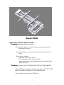
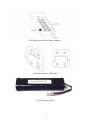
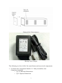
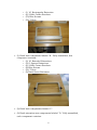
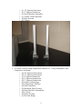
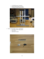
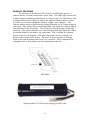
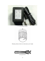
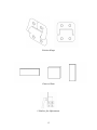
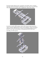
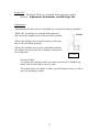
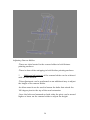
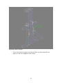
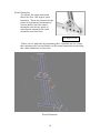
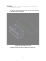
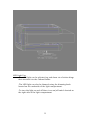
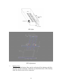
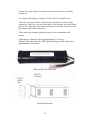
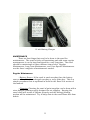
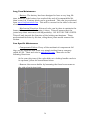
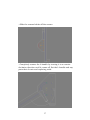
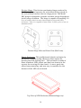
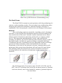
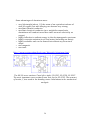
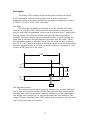
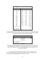
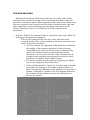
Easel 5000
Operator’s Manual
By: Alison Biercevicz
Seth Novoson
Justin Yu
Team 3
Patty Mitchell
Passion Works Studios
21S Campbell Street
Athens, OH 45701
(740) 592-6659, ext. 252
Easel 5000
IMPORTANT SAFETY INSTRUCTIONS
Warning: Pinching hazard at joints.
--Be sure that fingers are clear of any moving joint before
adjusting the easel.
--Only after fingers are clear of joints should one adjust the
easel
--These joints include
-The four 180 degree pivots
-The L brakes on the canvas holder
-Adjustable friction positioning hinge for the LED light
-Base fasteners
Warning: Product does CONTAIN ELECTRICAL COMPONENTS
--Keep LED light enclosure closed at all times. DO NOT OPEN
THE LED LIGHT UNDER ANY CIRCUMSTANCES
--Keep water away from the LED light.
2
--Keep paint and other painting supplies away from the LED
light
--Keep water away from the battery compartment
--Keep paint and other painting supplies away from battery
compartment
--Keep water away from the battery connectors
--Keep paint and other painting supplies away from the battery
connection
--When recharging battery first connect the battery to the
charger, then plug the charger into the wall socket
-DO NOT PLUG IN THE CHARGER FIRST, THEN CONNECT
THE BATTERY
--DO NOT CUT ELECTRICAL WIRES
--DO NOT TAMPER WITH ELECTRICAL WIRES OR
COMPONENTS
--DO NOT SHORT THE BATTERY. DOING SO WILL CAUSE THE
LEADS AND THE BATTERY TO HEAT UP WHICH CAN CAUSE
BURNS.
--Do not disassemble the canvas holder as the frame contains
electrical wiring.
Warning: Abuse of Velcro on Battery compartment can cause
loosening of battery.
--Avoid abuse of battery compartment and Velcro
Warning: Canvas holder could fall on user
--Be sure to tightened both locking handles at one joint before
letting go of the easel after adjustments have been made.
--Only loosen one L brake at a time
--Only let go of the easel after both sets of L brakes have been
tightened securely.
3
--Make sure both L brakes are tightened securely after
adjustment is finished.
--When adjusting the canvas holder make sure to adjust one L
brake at a time to avoid loosing control of the easel
Warning: Canvas can falls on user
--Check to make sure that the canvas clamp rubber stripping
contacts as much of the canvas frame as possible.
--Check that the canvas clamp is securely fastened and that the
canvas clamp locking handles have been tightened.
--Do not overload canvas holder
--Do not place materials larger than 9”X36” or 20”X24” into the
easel frame.
--Do not attempt to adjust the canvas clamping mechanism
while the canvas holder is over the artist.
--Do not attempt to adjust the canvas clamping mechanism
while the canvas holder is inclined forward.
--Make sure to retract the easel extension before adjusting
canvas clamp
--Use slots in the canvas holder when ever possible when
mounting a canvas
--Avoid Canvas weights in excess of ten pounds. Make sure that
both sets of locking mechanisms engage for canvas loads of over
3 pounds.
Warning: DO NOT OVER ADJUST DIMMING SWITCH ON THE LED
LIGHT
--The dimming switch has a maximum of one full turn
--Do not attempt to turn the dimming switch past one full turn
Warning: DO NOT LOOK DIRECTLY AT THE LED LIGHT
4
--If adjusting the LED light dim it or turn it off first
--Only after one is sure that the LED light is not facing a person
should one turn it on.
--Looking directly at the LED light for an extended period of
time can cause damage to one’s vision
Warning: DO NOT PLACE EXCESSIVE FORCE ON THE EASEL
--Do not use the easel for holding objects other than art paper
and cavases.
--The easel may be used to hold sheets of metal within the
specified weight range.
--DO NOT USE THE EASEL TO SUPPORT A PERSON’S WEIGHT
--DO NOT HANG OR LEAN ON THE EASEL
Warning: Do not use the easel if the base is not securely fastened to the
surface it is mounted on
--Failure to secure the base to the surface it is mounted on can
result in the easel falling on the artist
--Make sure both fasteners on the base are secured to its
mounting surface before use.
PARTS AND ACCESSORIES
The following is a pictorial list of the parts that comprise the easel.
In the package that came with this user's manual, you should have
the following easel components.
5
LED Light (attached to canvas holder)
Hinge attached to LED Light
9.6 Volt Battery Pack
6
Battery Pack Compartment
Battery Pack Charger
The following is a list of all of the easel frame and structural components
•
(1) Easel base component labeled "A." Fully assembled, this
component contains:
o (2) 16" Rounded Extrusions
o (2) 8" Square Extrusions
7
o
o
o
o
(1) 16" Rectangular Extrusion
(4) 2-Hole Corner Brackets
(12) Blue Screws
(18) T-Nuts
•
(1) Easel base component labeled "B." Fully assembled, this
component contains:
o (2) 16" Rounded Extrusions
o (2) 8" Square Extrusions
o (4) 2-Hole Corner Brackets
o (8) Blue Screws
o (14) T-Nuts
o (2) Knob Screw Fasteners
•
(2) Easel base components labeled "C."
•
(2) Easel extension arm components labeled "D." Fully assembled,
each component contains:
8
o
o
o
o
o
o
•
(1)
(1)
(1)
(1)
(5)
(5)
12" Square Extrusion
5" Square Extrusion
Pivot Bracket Assembly
4-Hole Corner Bracket
Blue Screws
T-Nuts
(1) Easel canvas clamp component labeled "E." Fully assembled, this
component contains:
o (3) 25" Square Extrusions
o (2) 21" Square Extrusions
o (1) 8" Square Extrusion
o (2) 2" Square Extrusions
o (2) 5" Square Extrusions
o (4) Linear Unibearings
o (2) Unibearing L-Brakes
o (2) End Fasteners
o (2) Stainless Steel Screws
o (2) Pivot Bracket Assemblies
o (18) T-Nuts
o (16) Blue Screws
o (1) Friction Hinge
9
o (1) LED System Assembly
o (4) LED Encasement Screws
o (1) Battery With Encasement
•
Packet of assembly parts containing:
o (6) 2-Hole Corner Brackets
o (8) T-Nuts
o (16) Blue Screws
10
PRODUCT FEATURES
The features of the Easel 5000 include an LED light source, a
canvas holder, an easel extension, and a base. The LED light source has
a light intensity dimming adjustment, an easy to use On/Off switch, and
an adjustable friction hinge to adjust the angle of illumination. It also
includes a 9.6 volt rechargeable battery supply, with charger. The
canvas holder easily adjusts using locking brackets to fit a large range of
canvases. The canvas size it accommodates can range not only in length
and width but also thickness. This allows for a large range of painting
medium. The easel extension has two locking joints that allow the easel
to extend forward, backward, up and down. Also it allows the canvas
holder to pivot 180 degrees. The base allows the easel to attach to a
wheel chair tray for ease of use. The base is then capable of locking
down via screw fasteners that lock it to a surface. Each component is
integrated into a functional unit for adjustment and use.
LED Light
Rechargeable 9.6 Volt battery supply for LED Light
11
12 Volt Battery Charger
Dimming Knob (located on underside of LED Light)
On/Off Switch
12
Friction Hinge
Canvas Sizes
L Brakes for Adjustment
13
TABLE OF CONTENTS
Introduction
About the Easel
Easel Assembly
Instructions
Easel Use
15
15
17
Adjustment
Attachment
LED Light
Maintenance
Technical
Description
LED Light
Power Source
LEDs
Circuit
PCB
Friction Hinge
Plastic
Enclosure
Easel Frame
Material
Easel Base
Easel Extension
Arms
Canvas Holder
Canvas Clamp
Mechanical
Analysis
Trouble
Shooting
References
27
27
31
32
35
46
46
46
46
49
53
54
54
55
55
57
57
59
59
60
67
70
14
INTRODUCTION
About the easel
The Easel 5000 is an adjustable easel designed for use by an artist with
physical limitations. The easel is made to adjust to a variety of positions
an artist would need when painting. It is fully mechanical with double
locking joints to ensure sturdiness and
safety. It is designed to attach to the tray of a
wheel chair for the artist’s use. The easel
design is broken up into four major
components. These components include an
LED light source, a canvas holder, an easel
extension, and a base. The LED light source
has a light intensity dimming adjustment, an
easy to use On/Off switch, and an adjustable
friction hinge to adjust the angle of
illumination. The canvas holder easily adjusts using locking brackets to
fit a large range of canvases. The canvas size it accommodates can range
not only in length and width but also thickness. This allows for a large
range of painting medium. The easel extension has two locking joints
that allow the easel to extend forward, backward, up and down. Also it
allows the canvas holder to pivot 180 degrees. The base allows the easel
to attach to a wheel chair tray for ease of use. The base is then capable
of locking down via screw fasteners that lock it to a surface. Each
component is integrated into a functional unit for adjustment and use.
LED Light
15
Front View
Side View
16
Back View
Assembly Instructions
Before you begin
Before you begin assembling the Easel 5000, make sure you have a full
set of hex-wrenches. These wrenches will be the only tools necessary to
completely assemble the easel.
Assembling the Easel 5000 Base
1. Locate the base component labeled "A." This component should be
assembled and contains:
a. (2) 16" Rounded Extrusions
b. (2) 8" Square Extrusions
c. (1) 16" Rectangular Extrusion
d. (4) 2-Hole Corner Brackets
e. (12) Blue Screws
f. (18) T-Nuts
17
2. Locate the base component labeled "B." This component should be
assembled and contains:
a. (2) 16" Rounded Extrusions
b. (2) 8" Square Extrusions
c. (4) 2-Hole Corner Brackets
d. (8) Blue Screws
e. (14) T-Nuts
f. (2) Knob Screw Fasteners
3. Attach the 2-hole corner brackets to the 2" square extrusions, labeled
"C," provided as shown.
18
4. Attach components A, B, and C as shown using t-slots, 2-hole
brackets, and screws to fasten components together.
19
The final Easel 5000 Base should look like the following.
Assembling the Easel 5000 Extension Arms
1. Locate the extension arm components labeled "D." These components
should be assembled and each contains:
a. (1) 12" Square Extrusion
b. (1) 5" Square Extrusion
c. (1) Pivot Bracket Assembly
d. (1) 4-Hole Corner Bracket
e. (5) Blue Screws
f. (5) T-Nuts
20
2. Attach component D to the completed easel base as shown using tslots, 4-hole brackets, and screws to fasten components together. Be
sure to have a 6 inch space between the two arms as shown.
21
The Easel 5000 should now look like the following with extension arms
attached to the base.
Assembling the Easel 5000 Canvas Clamp
1. Locate the canvas clamp component labeled "E." This component
should be assembled and contains:
a. (3) 25" Square Extrusions
b. (2) 21" Square Extrusions
c. (1) 8" Square Extrusion
d. (2) 2" Square Extrusions
e. (2) 5" Square Extrusions
f. (4) Linear Unibearings
g. (2) Unibearing L-Brakes
h. (2) End Fasteners
i. (2) Stainless Steel Screws
j. (2) Pivot Bracket Assemblies
k. (18) T-Nuts
l. (16) Blue Screws
m. (1) Friction Hinge
n. (1) LED System Assembly
o. (4) LED Encasement Screws
22
2. In order to attach the clamp component to the rest of the assembled
easel, it may be easiest to adjust the pivots of the extension arms
down flat as shown.
3. Remove the t-nuts found at the ends of the long blue screws of the
pivot bracket assemblies. These t-nuts have been placed here so that
the special long screws would not get separated from the assemblies.
The t-nuts are extras and are not necessary for the rest of the easel's
assembly, but they can be interchangeably used anywhere else on the
easel as replacement t-nuts.
23
4. Un-tighten the l-brakes on the pivot bracket assemblies so that they
are loose, but still on the assemblies.
24
5. Attach component E to the rest of the assembled easel. In order to do
this, you must ensure that the flat nub of the l-brake slides into the
slot of the extrusion. Then, the long blue screws of the pivot bracket
assemblies must be tightened all the way to fasten the pivots onto the
extension arms. Make sure both sides of the easel are fastened tightly
and are on evenly. The l-brakes previously loosened may now be
retightened. Minor adjustments may need to be made to suit the
artist's position and liking.
25
The Easel 5000 should now be completely assembled. After assembly,
the Easel 5000 should like the following. It is now ready to use with two
fully adjusting pivot points and an adjustable canvas size clamp.
In order to use the LED system, attach the battery to the back of the
canvas clamp by adhering the Velcro strips together. Plug in the battery
connector to the LED wire jack. Please see the following section titled
Easel Use for more instructions on adjusting the Easel 5000 and
operating the LED system.
26
Easel Use
The Easel 5000 use is broken down into three major
sections. Adjustment, Attachment, and LED Light Use.
Adjustment
-Adjustment for the easel is controlled by a series of locking L handles.
-When the L handles are rotated and tightened
clock wise the handles are in their locked position.
-When the handles are rotated counter clock wise
this is the unlocked position.
-When the handles are in their unlocked position
this allows the joint that the L handle is located at
to be adjusted.
L Handle
Canvas Holder-To adjust the canvas holder you must unlock the L handles on
either side of the holder one at a time.
-This then frees the holder to slide up and down in order to lock it
onto the painting surface.
27
Adjusting Canvas Holder
-There are slots located in the canvas holder to hold thinner
painting surfaces.
-There is also rubber stripping to hold thicker painting surfaces.
**
Additional adjustment of the canvas holder can be achieved
with an Alan wrench.
-This adjustment can be preformed as an additional way to adjust
the height of the canvas holder.
-An Alan wrench can be used to loosen the bolts that attach the
180 degree pivot to the top of the easel extension.
-Once the bolts are loosened on both sides the pivot can be moved
higher or lower on the canvas holder to adjust the height.
28
Adjusting Easel Height
-Once the desired height is achieved then an Alan wrench can
again be used to retighten these bolts.
29
Easel Extension-To adjust the easel extension
there are four 180 degree pivot
brackets. These are located at the
point of attachment between the
canvas holder and the easel
extension and at the point of
attachment between the easel
extension and the base.
180 Degree Pivot
-These can be adjusted by loosening the L handles one at a time
then pivoting the canvas holder on the easel extension or pivoting
the easel extension on the base.
Easel Extension
30
Attachment-Attachment for the easel is controlled by screw fasteners located
at the bottom of the base.
-The base can be slid onto a wheel chair tray and locked into place
by tightening the screw fasteners.
Sliding Base onto Wheel Chair Tray
-This locks the easel base onto the wheel chair tray for use.
31
LED Light Use-The LED light can be adjusted up and down via a friction hinge
that attaches it to the Canvas Holder.
-The LED light can also be dimmed using the dimming knob
located on the underside of the light compartment.
-To turn the light on and off there is an on/off switch located on
the right side of the light compartment
32
LED Light
LED Adjustment
**
Battery Use-To connect the battery line up the red wire of the battery with the
red wire of the connector, then line up the black wire of the battery
with the black wire of the connector.
33
-Insert the male end of the connector into the female end of the
connector.
-To charge the battery, remove it from its Velcro plastic box.
-Next line up the red wire of the battery with the red wire of the
connector, then line up the black wire of the battery with the black
wire of the connector and insert the male end of the connector into
the female end of the connector.
-Then with the charger provided plug it into a standard wall
socket.
-Charging is complete after approximately 8.5 hours.
-Battery run time with the LED light operating at full capacity is
approximately six hours.
Battery Pack for LED Light
Battery Enclosure
34
12 volt Battery Charger
MAINTENANCE
There are few things that need to be done to the easel for
maintenance. The easel is fairly self sustaining and with some regular
maintenance it can be kept functional for a very long time. The easel
should be maintained on three different time scales. Regular
Maintenance, Long Term Maintenance, and Case Specific Maintenance
are the three categories of maintenance needed.
Regular Maintenance--Battery Source: If the easel is used everyday then the battery
source will need to be recharged everyday or every other day. This is a
simple procedure that is explained in detail in the Easel Use section of
the manual.
--Cleaning: Cleaning the easel of paint supplies can be done with a
store bought cleaning supply designed for art supplies. Keeping the
easel clean will ensure it adjusts properly and the sliding/pivoting
motion will be maintained. Try to keep slots in the easel frame free from
debris.
35
Long Term Maintenance--Battery: The battery has been designed to have a very long life
time, however if the battery has reached the end of its expendable life,
than a new 9.6 V battery pack can be purchased. This can be purchased
from www.Onlybatteries.com. This will be covered in the table at the end
of maintenance.
--Mechanical Function: Not much else can be done to maintain the
frame of the easel besides keeping it clean. This will ensure that the
joints keep their movement and adjustability. DO NOT OIL THE JOINTS.
This will only impede the function of the locking mechanisms. These
mechanisms function by friction, oiling these joints would remove this
friction.
Case Specific Maintenance
--Components Failure: If any of the mechanical components fail
they can be replaced with some very simple tooling from a company
called 80/20. Their web site is www.80/20.com. Also refer to the
following directions.
In the event that one of the nylon disks at a locking handle needs to
be replaced, follow the instructions below:
--Remove the canvas holder by loosening the three hex screws on
the side of each pivot joint.
36
--Slide the canvas holder off the screws.
--Completely remove the L-handle by turning it in a counterclockwise direction until it comes off. Set the L-handle and any
parts that do not need replacing aside.
37
--Replace the nylon disk(s) on the L-handle assembly and reattach
the L-handle to the pivot joint.
-The large nylon washer must be a 1” outer diameter
(25.4mm) washer.
-If the entire L-handle assembly breaks another can be
ordered from AIR, Inc. in Framingham, MA or another 80/20
distributor. Part no. 25-2796
--After the part is replaced, reattach the L-handle assembly, and fit
the canvas holder onto the two pivot joint assemblies.
38
Replacing the battery. (Note: it should not be necessary to replace the
battery for quite some time, as it is rechargeable.)
--First, unclip the battery from the wires connecting it to the LED
system. The correct clips can be found at the base of the easel.
--Take the white battery enclosure off the easel.
39
--Remove the top of the white enclosure.
--Grasp the battery and pull the battery out.
40
--Insert new 9.6V 1700mAh battery into the white casing.
--Replace cap, and put the enclosure back onto the Easel.
41
Replacing the battery wiring after accidental wire severing.
--Warning! Rewiring a battery should only be done by a
professional because of a significant shock hazard!
Discharge the battery before attempting to replace the wire.
If there is no one with experience to do the repair do not
attempt to repair the battery wire.
Replacing the rubber stripping.
--Over time the rubber stripping may wear out and it may
become necessary to replace the stripping on the canvas
clamp and/or the canvas holder. To do this, follow the
directions below:
--Remove the worn rubber stripping; be sure to attempt to
remove as much of the remaining glue residue as possible.
--Cut new rubber stripping from a large piece of rubber to
21”x 3/8”. This may require cutting out more than one
strip of rubber, depending upon how many rubber strips
need to be replaced.
--Fit the rubber stripping on to the canvas clamp or canvas
holder.
Replacing the rubber stripping on the easel-to-table clamping device.
--Over time the rubber stripping may wear out and it may
become necessary to replace the stripping on the easel-totable clamps. To do this, follow the directions below:
--Remove the worn rubber stripping; be sure to attempt to
remove as much of the remaining glue residue as possible.
--Cut new rubber stripping from a large piece of rubber to
21”x 3/8”. This may require cutting out more than one
strip of rubber, depending upon how many rubber strips
need to be replaced.
--Fit the rubber stripping on to the canvas clamp or canvas
holder. Rubber stripping that has an adhesive surface is
the easiest material to use as a replacement solution.
Replacing Velcro stripping on the White battery box.
42
--Due to repeated removal of the battery enclosure from the
easel, the Velcro may weaken over time. Eventually it may
become necessary to replace the Velcro to ensure that the
battery enclosure remains attached to the easel.
--Remove the battery enclosure from the easel and unhook
the battery.
Gently remove the battery from the enclosure.
--Using a knife or other cutting tool, carefully remove each
of the three Velcro strips from the battery box.
--LED light Failing: If the entire LED light fails it can
be replaced by a store bought light. This is the suggested
means of replacement. Otherwise the technical description
can be referenced for further ideas on how to fix it.
Parts list
Easel
Section
Base
Base
Base
Base
Base
Base
Base
Base
Base
Base
Base
Part
Description
25-2525
extrusion
25-2527
extrusion
25-2550
extrusion
25-2525
extrusion
M6 threaded
rod
M6 threaded
female knobs
2 Hole inside
corner
brackets
BHSCS w/
Economy Tnut for 2 hole
inside corner
brackets
BHSCS w/
Economy Tnut for 252550 16"
length
Drop-in Tnut and Set
Screw
25-2550 End
80/20
Part #
unit
price
4
25-2525
$1.727
$6.91
406.4
4
25-2527
$2.845
$11.38
16
406.4
1
25-2550
$4.470
$4.47
2
50.8
2
25-2525
$0.406
$0.81
2.5
63.5
2
$0.900
$1.80
2
$2.160
$4.32
Length
(in.)
Length
(mm)
8.5
215.9
16
NA
Width
(in.)
# of
parts
Total
price
14
25-4108
$2.600
$36.40
NA
28
75-3404
$0.420
$11.76
NA
4
75-3404
$0.420
$1.68
NA
NA
4
2
25-3313
25-2025
$2.250
$1.250
$9.00
$2.50
43
caps
Extension
Arms
Extension
Arms
Extension
Arms
Extension
Arms
Extension
Arms
Extension
Arms
Extension
Arms
Canvas
Holder
Canvas
Holder
Canvas
Holder
Canvas
Holder
Canvas
Holder
Canvas
Holder
Canvas
Clamp
Canvas
Clamp
Canvas
Clamp
Canvas
Clamp
25-2525
extrusion
25-2525
extrusion
Pivot Bracket
Assembly
4 hole inside
corner
brackets
BHSCS w/
Economy Tnut
BHSCS w/
Economy Tnut for 4 hole
inside corner
brackets
25-2525 end
caps
25-2525
extrusion
25-2525
extrusion
25-2525
extrusion
BHSCS w/
Economy Tnut
25-2525 end
caps
Rubber
stripping
Canvas
Clamp
Canvas
Clamp
Canvas
Clamp
25-2525
extrusion
25-2525
extrusion
Unibearing
for 25-2525
L-brake
assemblies
End fastener
and stainless
steel screw
25-2525 end
cap
rubber
stripping
LED system
PCB
12
304.8
2
25-2525
$2.438
$4.88
5
127
4
25-2525
$1.016
$4.06
NA
4
25-4051
#
NA
2
25-4113
$3.850
$7.70
NA
18
75-3404
$0.420
$7.56
NA
8
75-3404
$0.420
$3.36
0
8
25-2015
$1.000
$8.00
25
635
3
$5.080
$15.24
21
533.4
1
$4.267
$4.27
8
203.2
1
$1.626
$1.63
$100.00
NA
6
75-3404
$0.420
$2.52
NA
8
25-2015
$1.000
$8.00
21
533.4
21
533.4
1
25-2525
$4.267
$4.27
2
50.8
2
25-2525
$0.406
$0.81
0
4
25-6760
0
2
25-6850
$9.050
$18.10
0
2
25-3682
$1.500
$3.00
0
4
25-2015
$1.000
$4.00
21
533.4
44
0.375
0.375
2
$0.00
$0.00
$50.00
2
$0.00
1
$99.87
Super Bright
LED
Potentiometer
Potentiometer
Knob
Battery 9.6V
1700 mAh
Battery
connector
20
1
1.51
$36.250
$1.51
1
5.13
$5.13
1
20.95
$20.95
1
2.99
$2.99
$505.12
Mechanical
Section
totals
25-2525
25-2527
25-2550
BHSCS w/
Economy Tnut
2 hole inside
corner
brackets
4 hole inside
corner
brackets
rubber
stripping
L-brake
handle
assembly
25-2525 end
caps
25-2550 end
caps
Pivot Bracket
assembly
25-2525
Unibearing
Drop-in Tnut and Set
Screw
End fastener
and stainless
steel screw
M6 threaded
rod
M6 threaded
female knobs
Length
(in.)
211
16
16
Length
(mm)
5359.4
406.4
406.4
Width
(in.)
# of
parts
1
4
1
80/20
Part #
25-2525
25-2527
unit
price
$2.845
$4.470
Total
price
$42.88
$11.38
$4.47
64
75-3404
$0.420
$26.88
14
25-4108
$2.600
$36.40
2
25-4113
$3.850
$7.70
2
PCB
Super Bright
2
25-6850
$9.050
$18.10
20
25-2015
$1.000
$20.00
2
25-2025
$1.250
$2.50
4
25-4051
$100.00
4
25-6760
$50.00
4
$2.250
$9.00
2
$1.500
$3.00
2
$0.900
$1.80
2
$2.160
$4.32
1
20
45
$0.00
$99.87
$36.250
LED
Potentiometer
Potentiometer
Knob
Battery 9.6V
1700 mAh
Battery
connector
Total cost
1
1.51
$1.51
1
5.13
$5.13
1
20.95
$20.95
1
2.99
$2.99
$505.12
List of Parts for Replacement
TECHNICAL DESCRIPTION
LED Light
LED Light
Power Source
This battery is a 9.6 volt battery pack. It operates at
1700mAh and is a nickel cadmium power supply. It is
configured as a flat stick pack with the dimensions 180 X 22
X 45 mm. It also has a standard tamiya connector and
includes a 12 volt battery pack charger for use in any
standard wall socket. The battery fully charges in 8.5 hours.
Its run time is approximately 6 hours. Its input is AC 120 V
at 60Hz and its output is DC 12V -200mA.
LEDs
The LED’s are super bright 5mm White 18,000mcd.
They are some of the brightest white LEDs available on the
market today. They are energy efficient as far as how much
46
power they dissipate. They often dissipate less than 100 mill
watts of power. Their useable life is longer than 100,000
hours which ensures years of use with reasonable use. The
way the LED works is fairly simple. It is a PN junction
semiconductor embedded in an epoxy matrix. This leaves no
loose or moving parts to break. When current is applied the
diode emits light of a certain intensity based on the
magnitude of the current. Most LEDs operate on a current
of 20 mA this circuit operates on 25 mA. This current
magnitude creates a brightness of 18,000 mcd. This is the
recommended brightness for art display in a gallery. Eye
safety for an LED this bright becomes an important factor.
DO NOT STARE DIRECTLY AT THE LEDS. In order to avoid
a problem with this LEDs with a luminous angle of 15
degrees was chosen. Also the way the friction hinge was
installed does not allow the LED enclosure to adjust in the
direction of the user. Also the dimming switch allows for a
variable brightness. A further feature of the LED light is the
low heat dissipation. This ensures the LEDs will not get too
hot to cause a safety concern.
LED Spec
Product ID
Angle
Package
Color
Peak Wavelength in
nm
Luminous Intensity
Max Forward
Current
Max Forward
Current Pulse
Value
L1-0-W5TH15-1
15
5mm
18000mcd typ. @
20mA
30mA
Forward Voltage
Max Reverse Voltage
Power Dissipation
Operating Temp
Soldering Temp
Max Reverse
47
100mA for <= 10ms,
duty <= 1/10
3.6V typ. 4.0V max @
20mA
5V
120mW
-30 to +85 C
265 C for 10 secs
50uA @ 5V
Current
LED Schematic
Zoom of Branch of LED Circuit
The above circuit shows two branches of the eight
branches of the LED circuit. This shows the combination of
LEDs in parallel and series. This combination of two in
series and eight branches in parallel for a total of 16 LEDs
let the circuit operate to maximum capacity. This let the
most LEDs run on the smallest power supply the appropriate
amount of current to each of the LEDs allowing them to burn
at maximum capacity. The NPN switching transistor at the
end of each branch is to ensure that the appropriate amount
48
of current is always being provided and the maximum
capacity of the LEDs is not surpassed. This is due to the
oscillating square wave provided by the LM555 that this
problem can arise.
Circuit
The following is the circuit diagram for the LED light of
the product. It includes resistances, LEDs, a power source,
transistors, capacitors, an LM555 chip, and a potentiometer.
There are important features and characteristics of the
diagram to note. The LM555 chip is a highly stable device
for generating accurate time delays or oscillation. When
configured in time delay mode it is controlled by one external
resistor and capacitor. It offers the ability to adjust the
oscillating duty cycle through the adjustment of resistor and
capacitor values. Coupled with the resistors and capacitors
values chosen for this application it creates a square wave
power source.
Schematic for LM555 (www.national.com)
49
Connection Diagram for the LM555 (www.national.com)
Example of basic setup of LM555 (www.national.com)
50
Example of Square waves created with LM555
(www.national.com)
This makes the LEDs operate off of an alternating
square wave. This mimics an AC source and saves battery
life by having the LED’s flash on and off very quickly so it is
not noticeable to the human eye. This means the LEDs are
only on half of the time therefore saving LED and battery life.
The operating voltage of the circuit is 9.6 volts. There is a
3.6 volt drop across each LED. Each transistor draws 1 mA
of current during the on part of the square wave. The
potentiometer operates as the dimming switch by creating a
larger voltage drop when the resistance is turned all of the
way up.
51
Entire LED Circuit (Express PCB)
Zoom of LM555 Chip in the Circuit (Express PCB)
The potentiometer operates as the dimming switch by
creating a larger voltage drop. When the resistance is turned
52
up to its maximum of 10 Kohm it creates a large voltage drop
and gives less voltage and current to the LEDs thus causing
them to burn less brightly. However when the resistance is
turned all of the way down then the only voltage drop is
across the 3.2 Kohm resistor. This causes the maximum
amount of voltage and current to be delivered to the LEDs
and thus allowing them to burn brightly.
Printed Circuit Board (PCB)
The following is a lay out for the circuit that was
adapted to a PCB. This is the way the circuit is set up inside
of the LED enclosure. Careful consideration had to be taken
when setting up the PCB in order to connect appropriate
wires, avoid crossing wires, and avoid shorting components
by placing them too closely. This took trial and error and
repeated checking of measurements. Further more many
custom foot prints had to be made to fit special parts like the
switch, battery, and potentiometer. One should take notice
DO NOT OPEN the PCB enclosure under any circumstances.
There is important and delicate circuitry inside that can be
damaged by art supplies, touch, or water.
PCB Schematic (Express PCB)
53
Friction Hinge- This friction positioning hinge produced by
Reell Incorporated operates via a frictional device placed in
the articulation between the two hinge pieces. The Model
PHC hinge is designed to provide constant torque throughout
its full range of motion. The hinge is capable of handling 3.9
lb-in of torque which is more than ample for the small LED
enclosure. Also it is capable of more than 10,000 cycles of use at
maximum load.
Friction Hinge Side and Front View (Reell.com)
Plastic Enclosure- This prefabricated plastic enclosure by
Hammond Manufacturing offered a perfect option for
housing the LED lighting unit. The enclosure is made of
flame retardant UL94 plastic and has bras inserts in the
corners for securing the box closed. It was a good size,
offered easy mounting, and was easy to machine for the
features of the LED circuit board.
Top View of LED Enclosure (Hammondmfg.com)
54
Side View of LED Enclosure (Hammondmfg.com)
The Easel Frame
The Easel 5000 is meant to assist painters with the positioning of a
canvas or other painting surface. Factors taken into consideration when
designing the easel were aesthetics, material strength, and ease of
adjustment. Each item played a critical role in the design of this project.
Material
After evaluating numerous materials, including, wood, aluminum,
and steel, it was decided that aluminum would be the best material for
the construction of the easel. Instead of plain aluminum stock, Easel
5000 is made of aluminum extrusion produced by a company called
80/20. This extrusion was lightweight, sturdy, and aesthetically
pleasing. In addition, the 80/20 extrusion was relatively cheap, could be
machined easily, and did not require welding to assemble the frame.
Considering the ease of assembly was very important during the design
process as easier assembly creates less headaches for the user.
Aluminum is also inert in the presence of water, meaning that acrylic
paints and other water-based mediums will not harm the easel frame.
The following table was found in the course of research and was a
deciding factor in the selection of aluminum as the construction
material.
The 80/20 materials: From left to right, 25-2525, 25-2550, and 252527. the 2527 extrusion was chosen for the base because a rounded
look was desired, and it also limited the number of pointed edges on
the easel base.
55
Some advantages of aluminum were:
•
•
•
•
•
•
•
•
very lightweight (about 1/3 the mass of an equivalent volume of
steel or copper) but with alloying can become very strong.
excellent thermal conductor
excellent electrical conductor (on a weight-for-mass basis,
aluminium will conduct more than twice as much electricity as
copper)
highly reflective to radiant energy in the electromagnetic spectrum
highly corrosion resistant in air and water (including sea water)
highly workable and can be formed into almost any structural
shape
non-magnetic
non-toxic
(http://www.engineershandbook.com/Materials/aluminum.htm)
The 80/20 cross sections: From left to right, 25-2525, 25-2550, 25-2527.
The most important cross sectional area was for the 25-2525. The moment
of inertia, I, was used in the bending stress calculations in the mechanical
analysis.
56
Description
The Easel 5000 consists of four main parts constructed from
80/20 extrusion, and the LED system, which was constructed
separately. Each of the four mechanical sections is composed of either
25-2525, 25-2550, or 25-2527 extrusion.
The Base
The base was designed specifically to fit the smaller table that
attaches to a wheel chair. The particular mechanism for securing the
easel to the table is embedded in the base in the form of a C-clamp style
locking clamp. The two knobs turn and drive the flat metal plates
upward. The metal plates are covered with rubber to avoid scoring the
table and to increase friction between the plates and the table. These
locking knobs tighten sufficiently to secure the easel so that it may be
used. 1.5” ( 38.1 mm) was taken as the table depth, and the metal plates
used are approximately 3/8th inch in depth, leaving a clearance of 1/8th
inch to fit the base on to the table.
0.22
0.05
The Extension Arms
The extension arms were originally designed as a single arm with
three joint articulations instead of two. Because of design requirement
changes from the first semester, stability reasons and cost constraints,
the design was changed to a 2 arm design with two articulations. The
range of motion that the Easel 5000 has is large enough so that the easel
can be used and has been tested.
57
In the diagram above the parts labeled D are the easel arms. Each of the
extension arm beams are made of 25-2525 80/20 extrusion that are each
12” (304.8mm) long. At the base are 2 dynamic locking pivot joints which
are bolted onto two, 5”(127mm) lengths of 25-2525.
58
The Canvas Holder
The Canvas holder was designed to accept up to a 20”X24”
canvas/art surface. This section of the easel also includes rubber
stripping, and when the canvas clamp is used in conjuction with the
canvas holder, the painting surface can be inclined so that the artist can
paint at an upward angle.
The Canvas Clamp
The sliding canvas clamp is the fourth mechanical part of the
easel. It also has rubber stripping which can be used to hold the canvas
or other art surface in place. Both the canvas clamp and canvas holder
have a slot in the center of the supporting beams where an art surface
could be place.
59
Mechanical Analysis
Although it was believed that the aluminum extrusion would have
no problem supporting the weight of the easel and canvas frame,
mechanical analysis was done to verify intuitive suspicions. Below is a
diagram of the forces used in calculating the stresses placed on the
easel, as well as a table with the mechanical stress analysis results. The
forces created by the weight of the easel created a moment of 13.52 N*m
about the set of hinges attached to the base. And the appropriate force
required to hold up the easel could be supplied by the locking levers.
Weight Calculations
The weights of each individual section were obtained by measuring
the unit length (in meters) and then plugging into the following
equations:
For lengths of 25-2525:
#
#
=
=
!
"
For lengths of 25-2527:
=
For lengths of 25-2550:
=
60
The table below shows the results of the weight calculations. These
results were used in the computation of the bending stresses and normal
stresses in respective selected aluminum extrusion lengths and screws
that were needed to hold the easel in place.
Total Weight
Number of
Section
(N)
pieces
Canvas Clamp
6.91
W1
13.91
W2
3.89
W3
1.48
W4
1.85
W5
4.45
W6
1.35
W7
1.85
W8
10.43
W9
6.31
W10
0.74
W11
5.20
W12
2.28
W13
4.64
WL
4.41
WHT
1.35
WB
11.07
total weight (N)
82.13
total weight (lbs)
18.46
61
Indiv.
Weight(N)
1
3
1
1
2
2
2
2
4
4
2
1
4
1
1
2
1
6.91
4.64
3.89
1.48
0.93
2.23
0.68
0.93
2.61
1.58
0.37
5.20
0.57
4.64
4.41
0.68
11.07
52.80
11.87
Fc
The diagram above was used to calculate the moment about the first set of
dynamic pivot joints at point C. For the ease of calculations, the two pivots
were taken as one, and the two easel arms were taken as one.
62
Moment about Point
C
Section
Wi (N)
Ri/b
W1
13.91
W2
3.89
W3
1.48
W4
1.85
W5
4.45
Wc
13.34922345
WL
4.41
W12
2.28
W13
4.64
WHT
1.35
WB
11.07
Totals about Point C
Fc (divided across 2
locking levers
1065.804501
(m)
Mi(N*m)
0.474
6.593
0.244
0.949
0.731
1.082
0.319
0.590
0.151
0.672
0.474
6.328
0.731
3.227
0.701
1.595
0.671
3.111
0.319
0.432
0.225
2.492
27.071
0.0254
27.071
Using the FBD shown in the previous diagram, the moment about point C
was found, and from that, the force required to hold the entire easel’s
weight in the configuration above.
Ff needed
Variable
Ff=Fc
Mu
Fn
Value
Unit(s)
1.07E+03 N
2.50E-01
4.26E+03 N
The table labeled Ff Needed shows the calculations for the force necessary
on the locking mechanism in order to hold the easel in place with only one
locking mechanism engaged.
63
Stress on the screws
Variable
Value
Units
Stress
1.51E+08 Pa
P
4.26E+03 N
A
2.83E-05 m^2
Assumed Structural
steel for yield point
(lowest of steels)
4.00E+08 Pa
Value (MPa)
150.780
400
Assuming that the screws used were made of the weakest steel, the stress
placed on the screw by the necessary compressive force was calculated.
The resulting stress of 150.7 MPa is less than the 400 MPa needed to
cause the steel to yield and thus the screws are able to withstand the
forces needed to support the easel with only one locking mechanism in
place.
Bending Stresses
sigma=M*c/I
M
C
I
sigma yield strength
Value
Units
1.94E+07 Pa
2.71E+01 N*m
1.27E-02 m
1.77E-08 m^4
1.35E+08 Pa
Value (MPa)
19.40
135
To ensure that the moment caused by the weight of the easel would not
cause the aluminum to yield, the Bending Stress calculations were
completed. The bending stress found (19.4 MPa) was much less than the
135 MPa need to yield the aluminum.
Note: for the above calculations, mechanical properties were taken from
(http://ussautomotive.com/auto/steelvsal/mechproperties.htm) and
(http://en.wikipedia.org/wiki/Tensile_strength)
Because one locking mechanism can be used to support the weight
of the easel and simulated canvas, the second serves as an equalizer and
secondary locking system. This is so that if one clamp is undone, the
positioning assistant can make sure he or she has a firm grip on the
easel before releasing the second clamp.
64
Mechanical analysis of the base provided the force necessary to
hold the easel in place and secure it to the table. The diagram below
shows the forces considered when calculating the moment about point D.
Note: The weights and forces denoted by W and F have Newton’s as units
of measurement.
65
Moment about Point
D
Section
Wi (N) Ri/b (m)
W1
13.91
0.363
W2
3.89
0.133
W3
1.48
0.62
W4
1.85
0.207
W5
4.45
0.041
W7
1.85
-0.11
(W8)/2
5.22
-0.229
W9
6.31
-0.11
W10
0.74
-0.229
W11
5.20
-0.11
W12
2.28
0.701
W13
4.64
0.671
Wc
13.34922 0.474
WL
4.41
0.62
WHT
1.35
0.207
WB
11.07
0.225
Totals about Point C
Mi(N*m)
5.049
0.517
0.918
0.383
0.182
-0.204
-1.194
-0.694
-0.170
-0.572
1.595
3.111
6.328
2.737
0.280
2.492
20.759
Fc (divided across 2
locking levers
124.3071
20.759
0.167
The table labled “Moment about Point D,” shows the calculated forces and
moments for the diagram above as well as the force necessary to stabilize
the easel on the table. This force is labeled Ft.
Stress on the screws
Variable
Value
Units
Stress
4.40E+06 Pa
P
1.24E+02 N
A
2.83E-05 m^2
Assumed Structural
steel for yield point
(lowest of steels)
4.00E+08 Pa
Value (MPa)
4.396
400
To ensure that the threaded rods bought would be able to function in the
role intended, the value of stress was determined. The stress put on the
screws (3.30 MPa) was far less thant the yielding stress of the screw’s
material (400 MPa).
The mechanical analysis showed that the easel would function
under normal operating parameters and the secondary locking system,
and the easel clamping system would work as well.
66
TROUBLE SHOOTING
Although Team Easel 5000 hopes that the use of the easel will be
seamless, this trouble shooting section has been included to help the
operator or assistant with common questions that may arise. Please note
that any repairs to the frame should be done by someone who has had
some experience in metalworking/woodworking and repairs to the
battery should be done by an individual who has experience in
electronics.
•
Problem: What if the canvas holder or extension arms move while the
locking mechanisms are engaged?
o This can be hazardous for the user if the problem is not
resolved quickly! The canvas holder or the arms can move as a
result of several situations:
If all the clamps are tightened sufficiently then checking
the weight of the material mounted is the next step.
Overloading the canvas with too heavy a material may
lead to the canvas holder readjusting without any
assistance. In this case, the size of the canvas must be
changed and a smaller painting surface must be used.
Please see the Safety Precautions section.
The most common problem may be forgetting to tighten
one of the clamps as described above.
If the problem persists, check the L-brakes and extension
arm joints for damage to the nylon (white) washers. If
there is significant damage to the washers or one of the Lbrakes, it should be replaced. See the diagram below for
the location of the washers and see the maintenance
section for details.
67
Problem: The battery keeps falling off. How do I fix it?
o This is usually caused by wear on the Velcro that happens over
time. Simply replace the Velcro stripping. See the maintenance
section for instructions on how to replace the Velcro.
•
•
Problem: LED lighting system doesn’t turn on. What’s wrong?
o Because the lighting system does not turn on does not mean
the system is broken.
If the LED system is left on overnight or has not been
recharged after prolonged use, it is possible that the
battery just needs recharging.
• To fix this simply plug the battery into the charger
for 8 and ½ hours to bring the battery back up to
full charge.
• Note: The battery’s runtime should be around 6
hours at full charge, so if it is left on by accident
overnight, then the battery will be drained.
If the battery is fully charged and the LED system still
does not work, check the LED enclosure to make sure
that no water, paint or other liquid has gotten into the
box. It is very important that the LED enclosure not be
opened, as a replacement of this particular device is not
possible.
If the LED box has been deluged with water, paint or
another substance, or the circuitry has been disturbed in
some way, the damage to the PCB inside may be
irreparable. In this case, another light may be purchased
online or from a local store and mounted onto the easel.
o Do not open LED casing as paint, water or other substance may
damage circuitry inside and may cause the device to stop
working.
o Do not open the LED casing while the device is on.
Problem: The canvas is sliding off the easel when the canvas holder is
inclined.
o Usually, the canvas clamp is not securely in place and as a
result, the frictional forces usually provided by the rubber
stripping is not great enough to hold the canvas in place.
To resolve this issue, tighten the canvas clamp onto the
frame of the canvas or other art surface. Make sure that
the rubber stripping contacts as much of the edge of the
canvas frame as possible.
o Another possible cause is that the material mounted in the
canvas clamp is too heavy.
In this case, the canvas being used should be downsized.
68
Do not overload the canvas holder
Do not place materials larger than 9”X36” or 20”X24” into
the easel frame.
Do not attempt to adjust the canvas clamping mechanism
while the canvas holder is over the artist.
o The last possibility and most unlikely is that the glue, attaching
the rubber stripping to the canvas holder or canvas clamp,
could be worn.
To fix this problem two options are available.:
• Glue the existing rubber stripping back on.
• Buy and cut new rubber stripping as described in
the maintenance section.
Either option should restore easel functionality.
Closing Remarks
We wish the best of luck to the artist and assistant. Much time and
energy went into the development and construction of this easel and we
know it will help. Please do not hesitate to contact us in the future if we
can be of any assistance!
-Team 3
69
REFERENCES
National Semiconductor. LM555 Timmer.
http://cache.national.com/ds/LM/LM555.pdf. April 11, 2006.
The LED Supply. Super Bright LEDs. http://www.ledsupply.com/.
December 1, 2005.
Reell Incorporated. Positioning Friction Hinge.
http://www.reell.com/downloads/drawings/reell_phc.pdf April 11,
2006.
Hammond Manufacturing. 599 Series box.
http://www.hammondmfg.com/pdf/1599E.pdf April 11, 2006.
Usautomotive.com. Steel vs. Aluminum: Mechanical Properties.
<http://ussautomotive.com/auto/steelvsal/mechproperties.htm> April
12, 2006. Updated April 13, 2006.
Wikipedia.org. Tensile Strength.
<http://en.wikipedia.org/wiki/Tensile_strength> April, 12, 2006.
updated April 2, 2006.
www.engineershandbook.com. Aluminum.
<http://www.engineershandbook.com/Materials/aluminum.htm> April
12, 2006.
70