1
MENTOR
MENTOR XT
User Manual
Issue 1.0
Lighting Technologies
ME 1113
1106.01.113
MENTOR & MENTOR XT System Manual
INDEX
1. Introduction ................................................................................................................................... 2 1.1 1.2 1.3 1.4 1.5 2. MENTOR ........................................................................................................................................ 4 2.1 2.2 2.3 3. Technical specifications ......................................................................................................... 8 Rear panel .............................................................................................................................. 9 Addressing ............................................................................................................................. 9 Interconnections between MENTOR and EXTENSION WING(S) ....................................... 11 EXTENSIONS supplied by MENTOR .................................................................................. 11 Extensions using its built-in 230 V power ............................................................................ 11 EXTENSION Module.................................................................................................................... 13 5.1 5.2 5.3 5.4 5.5 5.6 6. Technical specifications Desk ................................................................................................ 6 Front panel MENTOR ............................................................................................................ 6 Back plane MENTOR ............................................................................................................. 7 EXTENSION Wing ......................................................................................................................... 8 4.1 4.2 4.3 4.4 4.5 4.6 5. Technical specifications Desk ................................................................................................ 4 Front panel MENTOR ............................................................................................................ 4 Back plane MENTOR ............................................................................................................. 5 MENTOR XT ................................................................................................................................... 6 3.1 3.2 3.3 4. Delivery and Unpacking ......................................................................................................... 2 Preparing the Desk Location .................................................................................................. 2 Desk ....................................................................................................................................... 2 Power Supply ......................................................................................................................... 3 Electrical Connection ............................................................................................................. 3 Technical specifications ....................................................................................................... 13 Rear panel ............................................................................................................................ 13 Addressing ........................................................................................................................... 13 Interconnections between MENTOR and EXTENSION WING(S) ....................................... 13 EXTENSIONS supplied by MENTOR .................................................................................. 14 Extensions using its built-in 230 V power ............................................................................ 14 MOTION CONTROL Wing ........................................................................................................... 15 6.1 6.2 6.3 6.4 6.5 6.6 Technical specifications ....................................................................................................... 15 Rear panel ............................................................................................................................ 15 Addressing ........................................................................................................................... 15 Interconnections between MENTOR and EXTENSION WING(S) ....................................... 15 EXTENSIONS supplied by MENTOR .................................................................................. 15 Extensions using its built-in 230 V power ............................................................................ 16 7. Interconnections ......................................................................................................................... 17 8. ISIS® Software ............................................................................................................................. 18 8.1 8.2 9. Getting upgrades via the Internet ......................................................................................... 18 Main downloads ................................................................................................................... 18 Setup ............................................................................................................................................ 19 9.1 9.2 9.3 9.4 Software Configuration......................................................................................................... 20 User Configuration ............................................................................................................... 21 Hardware .............................................................................................................................. 22 SAVE and EXIT .................................................................................................................... 23 10. Notes ............................................................................................................................................ 24 www.adblighting.com
System Manual - page 1
Issue 1.1
MENTOR & MENTOR XT System Manual
1. Introduction
1.1 Delivery and Unpacking
As soon as you receive your equipment, open the boxes and inspect the items received. If
you discover any damage, contact the carrier immediately and make any necessary claim for
the problems discovered.
The equipment was checked before being packed left our factory it in perfect condition.
Check that the equipment supplied to you corresponds to the consignment note and that this
corresponds to your order. You will find the references of your desk on an identification label
affixed to the rear panel.
If there is any discrepancy in the order and delivery, contact your supplier immediately who
will clarify the situation to your full satisfaction.
Permissible storage conditions:
Temperature: -10 to +50° C: variation rate: 20°/hour
Relative humidity: 20 to 80 % without condensation.
1.2 Preparing the Desk Location
The surface of your work area should be smooth, level and sturdy.
Make sure that there is enough clearance around the desk to:
• open the desk
• access the rear connections
• allow air circulation around vents to prevent the desk from over-heating.
1.3 Desk
The MENTOR and MENTOR XT desk is a professional lighting console with, it is Class I
equipment designed and manufactured to the EN60950 standard.
THIS EQUIPMENT MUST BE EARTHED.
No special provisions need to be made for the installation of the equipment. The room in
which the equipment is to be installed must be clean, dust-free and have a temperature
between 5 and 35° C and a relative humidity from 20 to 80 % without condensation.
Consumption of food and drink over the desk is inadvisable to avoid waste being accidentally
dropped into the equipment and impairing certain functions.
The desk and the monitor should be installed on a table or a console. Like all equipment
which includes microprocessors and uses similar technology, the desk is sensitive to the
influences of static electricity and it is possible that these influences will affect functioning in
certain circumstances. If this is the case, it will be necessary to place anti-static carpets on
the floor and perhaps to make the atmosphere more humid. Whenever a carpet is to be
used, it must be an antistatic carpet.
In order to avoid wasting time and possibly damaging the equipment, the installer is invited to
scrupulously follow the instructions in the diagrams shown, and on the rear panel of the ISIS®
based desk.
Before powering up the desk or any of its peripherals, check that the existing voltages are
within the limits defined in the TECHNICAL SPECIFICATIONS paragraph.
Note: all connections should be made with the power turned off, otherwise functioning may
be affected and can even damage the equipment under certain conditions.
www.adblighting.com
System Manual - page 2
Issue 1.1
MENTOR & MENTOR XT System Manual
1.4 Power Supply
Like all equipment used in computer systems, your system is sensitive to the characteristics
of the network and in particular to variations and voltage peaks.
Consequently, we advise you to use an appropriate line conditioner on this equipment.
Please consult us if you are in any doubt about this.
The line is to be protected by fuse or by circuit breakers and is to be provided with an earth
connection for personal safety.
Important Notice for Power Cables
Power cables and connectors are an important part of your equipment and contribute to its
safety.
Always use the connector to make or interrupt the link; never pull on the cable.
Do not damage the cable or the connectors in any way; do not pinch or tie together power
supply and signal cables, check them at each installation and at regular intervals on a
permanent installation.
1.5 Electrical Connection
TO PREVENT THE RISK OF ELECTRIC SHOCK, DO NOT OPEN THE DESK.
THERE ARE NO USER SERVICEABLE PARTS WITHIN. REFER SERVICING TO
QUALIFIED ENGINEERS ONLY. LETHAL VOLTAGES ARE PRESENT INSIDE!
ALWAYS DISCONNECT FROM THE POWER SUPPLY BEFORE OPENING FOR
INSPECTION.
MENTOR-range is professional lighting control systems developed with simplicity of use in
mind. In order to maintain the proficiency of the built in safety features, this equipment shall
be installed and maintained by qualified service personnel only.
www.adblighting.com
System Manual - page 3
Issue 1.1
MENTOR & MENTOR XT System Manual
2. MENTOR
2.1 Technical specifications Desk
•
•
•
•
Power supply: 85 to 264 V - 50 / 60 Hz
The ID label of the console is found on the inside and outside of the bottom panel. It
includes Part Number (1AX xxx xxx xxx), serial number, rated voltage, CE marking.
Dimensions: 727 x 525 x 128 mm
Weight: 12.3 kg
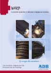
2.2 Front panel MENTOR
www.adblighting.com
System Manual - page 4
Issue 1.1
MENTOR & MENTOR XT System Manual
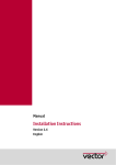
2.3 Back plane MENTOR
1
AUDIO IN
XLR 3 F
2
EXTENSION LINK
DB 15 F
3
EXTERNAL LINES
DB 9 F
4
DMX 1 0UT
XLR 5 F
5
DMX2 OUT
XLR 5 F
6
ON/OFF BUTTON
7
12V for gooseneck light
8
FUSE 12V GOOSENECK LIGHT - Internal fuse auto reset
9
POWER SUPPLY / POWER SUPPLY SWITCH
10
KEYBOARD
11
SVGA
12
Not USED
13
Not USED
14
USB
15
NOT USED
16
KEYBOARD
17
PARRALLEL
18
LAN ETHERNET
19
SERIAL
XLR 3 F
Points 10 to 19 are subject of the motherboard and could change depending revision of
motherboard.
www.adblighting.com
System Manual - page 5
Issue 1.1
MENTOR & MENTOR XT System Manual
3. MENTOR XT
3.1 Technical specifications Desk
•
•
•
•
Power supply: 85 to 264 V - 50 / 60 Hz
The ID label of the console is found on the inside and outside of the bottom panel. It
includes Part Number (1AX xxx xxx xxx), serial number, rated voltage, CE marking.
Dimensions: 1250 x 475 x 130 mm
Weight: 15 kg
3.2 Front panel MENTOR
www.adblighting.com
System Manual - page 6
Issue 1.1
MENTOR & MENTOR XT System Manual
3.3 Back plane MENTOR
1
12V for gooseneck light – Internal fuse auto reset
XLR 3 F
2
POWER SUPPLY / POWER SUPPLY SWITCH
3
AUDIO IN
XLR 3 F
4
EXTENSION LINK
DB 15 F
5
EXTERNAL LINES
DB 9 F
6
DMX 1 0UT
XLR 5 F
7
DMX2 OUT
8
ON BUTTON
9
Fixing point extension module
10
KEYBOARD
11
SVGA
12
Not USED
13
Not USED
14
USB
15
NOT USED
16
KEYBOARD
17
PARRALLEL
18
LAN ETHERNET
19
SERIAL
20
2 or 4 SVGA output (Option)
21
Not USED
XLR 5 F
Points 10 to 19 are subject of the motherboard and could change depending revision of
motherboard.
www.adblighting.com
System Manual - page 7
Issue 1.1
MENTOR & MENTOR XT System Manual
4. EXTENSION Wing
4.1 Technical specifications
•
•
•
•
Power supply: 230 V – 50 / 60 Hz
The ID label of the console is found on the inside and outside of the bottom panel. It
includes Part Number (1AX xxx xxx xxx), serial number, rated voltage, CE marking.
Dimensions: 380 x 450 x 130 mm
Height: 4.7 kg
www.adblighting.com
System Manual - page 8
Issue 1.1
MENTOR & MENTOR XT System Manual
4.2 Rear panel
1
EXTENSION LINK IN
DB 15 M
2
EXTENSION LINK OUT/THRU
DB 15 F
3
POWER SUPPLY
4.3 Addressing
Each MENTOR can be extended with up to 4 EXTENSION Wings. Each of the Wings has its
own address. The address is set by way of jumper inside the EXTENSION wing. The factory
setting for each Wing is address 1.
In case that more than one Wing is connected to a MENTOR it is necessary to configure the
address.
Selecting the address of the Wing
1. Remove the screw on the bottom panel, and open the Wing.
www.adblighting.com
System Manual - page 9
Issue 1.1
MENTOR & MENTOR XT System Manual
2. The Pin header to address the Wing is placed on the front pcb board. The pin header
is below the 26 pin connector.
3. The sketches below show the different settings for each possible wing address. ON
Left to right: wing addresses 1, address 2, address 3 and address 4.
www.adblighting.com
System Manual - page 10
Issue 1.1
MENTOR & MENTOR XT System Manual
4.4 Interconnections between MENTOR and EXTENSION WING(S)
Each wing is standard delivered with:
• an ‘extension link’ cable of 1.5 m
• a set of self’s-adhesive numbering labels
• a power supply cable (230 V)
Up to two EXTENSION WINGS can receive their dc supply voltage from the MENTOR, via
the Extension Link cable. Each Wing is fitted with a built-in 230 V power supply.
The two paragraphs below describe how to link the EXTENSIONS:
• one or two EXTENSIONS supplied by MENTOR
• EXTENSIONS using their built-in 230 V power supply
4.5 EXTENSIONS supplied by MENTOR
Only possible in case if using up to 2 wings with the standard extension link cable (delivered
with Extension). For any other configuration, please refer to paragraph ‘Extension using its
built-in 230 V power supply’.
4.6 Extensions using its built-in 230 V power
Use of the built-in power supply is mandatory:
• when you use an Extension cable longer than 1.5 m
• when you connect more than 2 wings to one MENTOR. Use of the built-in power
supply is then mandatory for the third and fourth Extension (irrespective of cable
length).
The factory setting for each Wing is: External power supply ON, ready to be supplied from a
MENTOR. Built-in supply set to off.
(Note: the built-in power supply will not supply dc to other Wings).
Enabling the external Power supply:
1. Remove the screw on the bottom panel, and open the Wing.
www.adblighting.com
System Manual - page 11
Issue 1.1
MENTOR & MENTOR XT System Manual
2. The Pin header to select the dc power source address is placed on the bottom pcb
board.
3. The sketch below gives the settings for the power supply. Left to Right: built-in 230 V
power supply; external dc power supply (factory default setting).
www.adblighting.com
System Manual - page 12
Issue 1.1
MENTOR & MENTOR XT System Manual
5. EXTENSION Module
5.1 Technical specifications
•
•
•
•
Power supply: 230 V – 50 / 60 Hz
The ID label of the console is found on the inside and outside of the bottom panel. It
includes Part Number (1AX xxx xxx xxx), serial number, rated voltage, CE marking.
Dimensions: 380 x 450 x 130 mm
Height: 4.7 kg
5.2 Rear panel
1
EXTENSION LINK IN
DB 15 M
2
EXTENSION LINK OUT/THRU
DB 15 F
3
POWER SUPPLY
5.3 Addressing
Each MENTOR can be extended with up to 4 EXTENSION Wings. Each of the Wings has its
own address. The address is set by way of jumper inside the EXTENSION wing. The factory
setting for each Wing is address 1.
In case that more than one Wing is connected to a MENTOR it is necessary to configure the
address.
Selecting the address of the Wing
4. Remove the screw on the bottom panel, and open the Wing.
5. The Pin header to address the Wing is placed on the front pcb board. The pin header
is below the 26 pin connector.
6. The sketches below show the different settings for each possible wing address. ON
Left to right: wing addresses 1, address 2, address 3 and address 4.
5.4 Interconnections between MENTOR and EXTENSION WING(S)
Each wing is standard delivered with:
• an ‘extension link’ cable of 1.5 m
• a set of self’s-adhesive numbering labels
• a power supply cable (230 V)
Up to two EXTENSION WINGS can receive their dc supply voltage from the MENTOR, via
the Extension Link cable. Each Wing is fitted with a built-in 230 V power supply.
The two paragraphs below describe how to link the EXTENSIONS:
• one or two EXTENSIONS supplied by MENTOR
• EXTENSIONS using their built-in 230 V power supply
www.adblighting.com
System Manual - page 13
Issue 1.1
MENTOR & MENTOR XT System Manual
5.5 EXTENSIONS supplied by MENTOR
Only possible in case if using up to 2 wings with the standard extension link cable (delivered
with Extension). For any other configuration, please refer to paragraph ‘Extension using its
built-in 230 V power supply’.
5.6 Extensions using its built-in 230 V power
Use of the built-in power supply is mandatory:
• when you use an Extension cable longer than 1.5 m
• when you connect more than 2 wings to one MENTOR. Use of the built-in power
supply is then mandatory for the third and fourth Extension (irrespective of cable
length).
The factory setting for each Wing is: External power supply ON, ready to be supplied from a
MENTOR. Built-in supply set to off.
(Note: the built-in power supply will not supply dc to other Wings).
Enabling the external Power supply:
4. Remove the screw on the bottom panel, and open the Wing.
5. The Pin header to select the dc power source address is placed on the bottom pcb
board.
6. The sketch below gives the settings for the power supply. Left to Right: built-in 230 V
power supply; external dc power supply (factory default setting).
www.adblighting.com
System Manual - page 14
Issue 1.1
MENTOR & MENTOR XT System Manual
6. MOTION CONTROL Wing
6.1 Technical specifications
•
•
•
•
Power supply: 230 V – 50 / 60 Hz
The ID label of the console is found on the inside and outside of the bottom panel. It
includes Part Number (1AX xxx xxx xxx), serial number, rated voltage, CE marking.
Dimensions: 380 x 450 x 130 mm
Height: 4.7 kg
6.2 Rear panel
1
EXTENSION LINK IN
DB 15 M
2
EXTENSION LINK OUT/THRU
DB 15 F
3
POWER SUPPLY
6.3 Addressing
6.4 Interconnections between MENTOR and EXTENSION WING(S)
Each wing is standard delivered with:
• an ‘extension link’ cable of 1.5 m
• a set of self’s-adhesive numbering labels
• a power supply cable (230 V)
Up to two EXTENSION WINGS can receive their dc supply voltage from the MENTOR, via
the Extension Link cable. Each Wing is fitted with a built-in 230 V power supply.
The two paragraphs below describe how to link the EXTENSIONS:
• one or two EXTENSIONS supplied by MENTOR
• EXTENSIONS using their built-in 230 V power supply
6.5 EXTENSIONS supplied by MENTOR
Only possible in case if using up to 2 wings with the standard extension link cable (delivered
with Extension). For any other configuration, please refer to paragraph ‘Extension using its
built-in 230 V power supply’.
www.adblighting.com
System Manual - page 15
Issue 1.1
MENTOR & MENTOR XT System Manual
6.6 Extensions using its built-in 230 V power
Use of the built-in power supply is mandatory:
• when you use an Extension cable longer than 1.5 m
• when you connect more than 2 wings to one MENTOR. Use of the built-in power
supply is then mandatory for the third and fourth Extension (irrespective of cable
length).
The factory setting for each Wing is: External power supply ON, ready to be supplied from a
MENTOR. Built-in supply set to off.
(Note: the built-in power supply will not supply dc to other Wings).
Enabling the external Power supply:
7. Remove the screw on the bottom panel, and open the Wing.
8. The Pin header to select the dc power source address is placed on the bottom pcb
board.
9. The sketch below gives the settings for the power supply. Left to Right: built-in 230 V
power supply; external dc power supply (factory default setting).
www.adblighting.com
System Manual - page 16
Issue 1.1
MENTOR & MENTOR XT System Manual
7. Interconnections
DMX
Cable length:
Cable size:
max. 250 m
2 x 0.34 + 0.34 mm², shielded twisted pair
AUDIO
Cable length:
Cable size:
max. 250 m
2 x 0.34 mm², shielded
External lines
Cable length:
Cable size:
max. 15 m
9 x 0.34 mm²
www.adblighting.com
System Manual - page 17
Issue 1.1
MENTOR & MENTOR XT System Manual
8. ISIS® Software
The ISIS® software for MENTOR and PHOENIX XT range is distributed via the internet or on
a CD-ROM
8.1 Getting upgrades via the Internet
The latest ISIS® software version can be downloaded from the ADB download area.
http://www.adblighting.com/?page=downloads
In the download area you will find the latest release as well as older versions. Under ISIS® 2
Software the following downloads are available.
8.2 Main downloads
•
ISIS® 2 Full - ISO image file
•
ISIS® 2 Small - ISO image file
No Wi-Fi Software, No USB, No documents
•
ISIS® 2 USB - for USB installation
Download "Install from USB Stick" for instructions
•
ISIS® 2 – VMWare
-VMWARE ™ image file
•
ISIS® 2.22 Translator
•
Install from USB stick
Instructions to install ISIS® 2 from a USB stick
•
BOOTUSBDev
USB Device boot floppy disk
•
Wi-Fi Software
Wi-Fi Remote Control V1.24 (Build 10)
www.adblighting.com
System Manual - page 18
Issue 1.1
MENTOR & MENTOR XT System Manual
9. Setup
After LINUX and ISIS® are installed, ISIS® automatically boots after a power up into the
System Setup. If there are no hardware changes or extra channels, you need to update the
name of the desk in de hardware section. If you have changes, you need to initialize these
changes in the appropriate part of the Setup program.
After the configuration, select <SAVE and EXIT>; the system will automatically reboot.
Note: It is also possible to System Setup from ISIS® main software.
examples of keystrokes:
<MENU> <F1{File}> <F8{System Setup}> <Enter>
www.adblighting.com
System Manual - page 19
Issue 1.1
MENTOR & MENTOR XT System Manual
9.1 Software Configuration
Field
Explication
Name
Customer Name
Address
Customer address
Zip Code
Customer Zip Code
City
Customer City
Country
Customer Country
Max Chan.
Standard amount Channels/Instruments
Upgradeable by blocks of 120 channels for
MENTOR and by block of 512 channels for
MENTOR XT
Extra channels requires a new software key
Network
Amount of DMX universes trough Ethernet
Use network login
Enable ‘use network login’ only if installation
is setup by ADB certified network specialist
Remember password for xx minutes
Related to “use network login”
NetCard SN
Unique serial number of desk
Necessary to order a new software Key
Key
ISIS® software Key
In relation with Netcard SN and amount of
channels/instruments
www.adblighting.com
System Manual - page 20
Issue 1.1
MENTOR & MENTOR XT System Manual
9.2 User Configuration
Field
Explication
Language
Selection of Language
New Label
Selection between Latin or Cyrillic character
set
Keyboard
Selection of keyboard type
Current Time
New Time
Possibility to change time
Current Date
New Date
Possibility to change date
www.adblighting.com
System Manual - page 21
Issue 1.1
MENTOR & MENTOR XT System Manual
9.3 Hardware
Field
Explication
Desk type
Selection of desk type
Laptop does not require a software key
Act as remote screen
Desk will act as a remote monitor – no desk
functions available
VGA type
Select type of VGA card:
Important => wrong selection will give no
display on the screens.1
Numb. Of Mon.
Numbers of monitors
Color Set
Selection between different colour sets
Desk DMX Out lines
Standard for MENTOR and MENTOR XT 2
DMX Default
Set the network universes selected to default
H.F. Remote Control
Only for old disabled HF products
DMX-Lines configuration
Possibility to change start address of DMX
line and length of DMX line
Mouse Type
Select type of Mouse
Name
IP
Important to give a name to your desk:
Ex: Master
IP address in Artnet – Please do not change
unit you are a network specialist
1
If no displays are show, it is possible to boot your desk in save mode. Press during booting E on you
alphanumeric keyboard. The desk will boot in one screen mode and allow you to reconfigure your
screens
www.adblighting.com
System Manual - page 22
Issue 1.1
MENTOR & MENTOR XT System Manual
9.4 SAVE and EXIT
After the configuration, select <SAVE and EXIT>; the system will automatically reboot in
ISIS®.
www.adblighting.com
System Manual - page 23
Issue 1.1
MENTOR & MENTOR XT System Manual
10. Notes
www.adblighting.com
System Manual - page 24
Issue 1.1
Subject to modifications
N.V. ADB-TTV Technologies S.A.
(Group Headquarters) Leuvensesteenweg 585, B-1930 Zaventem
Tel : 32.2.709.32.11, Fax : 32.2.709.32.80, E-Mail : [email protected]
Deutschland ADB GmbH
Boschstrasse 3, D-61239 Ober-Mörlen
Tel : 49.6002.93.933.0, Fax : 49.6002.93.933.33, E-Mail : [email protected]
France
Sales Office: 168/170, boulevard Camélinat F-92240 Malakoff
Tel : 33.1.41.17.48.50, Fax : 33.1.42.53.54.76, E-Mail : [email protected]
ADB S.A.S.
Factory & Group Logistics Centre: Zone industrielle Rouvroy F-02100 Saint-Quentin
Tel : 33.3.23.06.35.70, Fax : 33.3.23.67.66.56, E-Mail : [email protected]
www.adblighting.com
Lighting Technologies
M-1113-E-1n
ADB - Your Partner for Light
Belgium