1
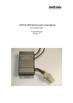
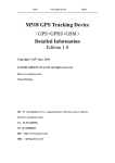
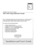
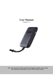
Cruise Vehicle Tracking Device Model No.: M588T(Third Version) (GPS+GSM+SMS/GPRS) User Manual Copyright © 2015 GATOR GROUP CO., LTD. All rights reserved. 1 / 12 Notes: Please mount the device steadily on the flat place before using; Please make sure the voltage value is right before connecting with battery, and placing the wires to where shouldn’t be trodden; Please power off when plugging or taking out of any module or connector; Please keep the device dry and don’t let any liquid fall into the device in case any damage caused in the device or circuit; If any problem caused as follows, please turn to professional technician: When power wire, keyboard, or socket are damaged; When liquid infiltrating into the device; When the device work unusually or cannot resume to normal even operated according to the instruction; When the device cannot work as usual after falling, throwing or breaking; When there is obvious damage in the device. Content 1. Product Introduction ···············································································································3 2. Characteristics ··························································································································4 2.1 Red LED (power/working status)……………………………………...…………………4 2.2 Blue LED(GPS status indicator)………………………………………………………….4 2.3 Yellow LED(GSM status indicator…………………………….………………………..4 2.4 Pecification…. ..…………………………………………………………………………..5 2.5 Device outlet specification………………………………………………………………...5 2.6 Device wiring diagram…………………………………………………………………….6 3. Method of installation............................................................................................................7 3.1. Preparation before installation························································································· 7 3.2. Installation ······················································································································ 7 4. Web based tracking online activation ···················································································7 5. SMS Configuration ··················································································································8 6.Trouble shooting……………………………………………………………………….. ..11 7. Standard Accessories……………………………………………………………………….12 2 / 12 1. Product Introduction GPS Tracking device mainly consists of two parts such as GPS module and GSM module. GPS module is for getting location data from satellite, and GSM module is for transferring data to server so that people can check the information via PC or mobile phone. Our GPS Tracking device, with the best quality, stable performance and versatile functions,can be applied to various kind of fleet management like construction trucks, rental cars, logistics vehicles and public transportation, anti-theft system and security purpose. 3 / 12 2. Characteristics 1) GSM 850/900/1800/1900 Quad band 2) Wide for voltage input range: 11-50VDC(can customized 40-90VDC) 3) GPS continuous positioning, GPRS timing interval 4) Support check location via SMS 5) Built-in vibration sensor, theft-proof 6) ACC ignition detection, car status prompt 7) Support Tele-cutoff (petrol/ electricity) remotely 8) Support setting three SOS numbers for voice monitoring remotely and received SOS alarm 9) Support connect SOS button to emergency Call for help 10) Support Voice monitor function 11) Support power off alarm when the power supply is disconnected intentionally (with backup battery) 12) Support geo-fence alarm, over speed alarm 2.1 Red LED (power/working status) 2.2 LED Status Meaning Fast Flashing (bright 0.1s dark 4s) Slow flashing(bright 1s dark 2s) Continuously in dark state Working normally Low battery power off/Internal fault Blue LED(GPS status indicator) LED Status Meaning Fast Flashing (bright 0.1s dark 4s) Slow flashing(bright 1s dark 2s) Continuously in dark state GPS located Searching GPS signal GPS not located 2.3 Yellow LED(GSM status indicator) 4 / 12 LED Status Meaning Fast Flashing (bright 0.1s dark 4s) Slow flashing(bright 1s dark 2s) Continuously in dark state GSM/GPRS working Start GSM No GSM signal 2.4.Pecifications Items work voltage work current GSM module Communication protocol GPS module GPS sensitivity C/A coding Channels Position accuracy Cold boot Work temperature Humidity Terminal size Gravity Acceleration Operating Temperature Humidity Size weight Parameters 11VDC-50VDC About 55mA inside contain frequency GSM 850/900/1800/1900Mhz TCP GPS MTK3337 -165dBm L1,1575.42MHz C/A code 22 channels examine track 5-15m 26s -20~70℃ 5% to 95% noncondensing 90mm × 45.5mm ×14.5mm <4g -20℃—65℃ 5%—95% 40mm*30mm*12.5mm 50g 2.5 Device outlet specification Line No. 1. 2 3. 4 5 6 7.8 Specification microphone Power ACC MOTOR SOS button Color red/black Black(V-) red (V+) white Green red, black Instruction Connect to Microphone Connect to vehicle storage battery Connect to ACC ignition Connect to relay control line Connect SOS button Notes of the relay wiring The relay wiring of pump: oil connectors of both ends are a fine white line (85) and a fine Green line (86). The fine white line (85) is connected to vehicle positive power (+12V). The fine green line is connected to the device relay control line. Cut off the positive connection line of the pump; then connect in series to the relay N.C. contact (thick green line 87a) and the other end to relay COM contact (thick green line 30). Note: The standard relay is 12V and only suits the 12V car battery. Please choose 24V relay if it is 24V car battery. 5 / 12 2.6 Device wiring diagram 6 / 12 3. Method of installation 3.1. Preparation before installation 3.1.1 Open the packing box to check whether the type of device is correct and whether the accessories are included, or else please contact your distributor. 3.1.2 Choose SIM card: each device needs to insert a GSM SIM card. Please refer to the distributor’s suggestions to choose the SIM card. 3.1.3 Installing SIM card into the tracker, open the device with screwdriver and put the SIM card into the tracker (do not insert the SIM card backwards). Note: Power off before installing SIM card , or removing the SIM card The SIM card should have GPRS charge Ensure the SIM card is able to send the receive SMS 3.2 Installation The device installation is covert. Please refer installation to an auto electrical contractor. NOTE: 3.2.1 To prevent theft of the device, it should be installed as covertly as possible. Covertly installation is suggested. 3.2.2 Avoid placing the device close to higher power electrical devices, such as reversing radar, anti-theft device or other vehicle communication equipment; 3.2.3 The device should be fixed into position with cable ties or wide double-side tape. 3.2.4 The device has built-in GSM antenna and GPS antenna. During installation, please make sure the receiving side face is up, with no metal object above the device to interfere with GPS reception. The following places are suggested for installation: -shelter in the decorated board below the front windshield; -shelter around the front instrument panel (non-metallic material face); -in the decorated board below back windshield; 4. Web based tracking online activation The GPRS web based tracking platform allows real time tracking with the latest Google maps. Service platform login website : http://211.154.139.208:8000/webgps/ Vehicle management platform website :http://211.154.139.208:8000/vms/ After you added device successfully on the VMS platform , you can send the SMS Commands to activate device SMS command format : ss,*apn*,*apn_username*,*apn password*,*ip*,*port*,*123456* 7 / 12 e.g.: ss,*cmnet*,**,**,*211.154.139.208*,*8872*, *123456* Notes: If no username and password, please leave it blank, e.g: SS, *apn*,**,**,*IP*,*Port* ,*Password* the system number on the platform should be the last 11digital number of device IMEI eg: if your device IMEI number is 356814563232141 the system number on platform should be : 14563232141 5. SMS Configuration Function change password Command pwd,*old_pwd*,*new_pwd* Eg : pwd,*123456*,*666666* set SOS number specific service,*phonenumber 1*,*phone number 2*,*phone number3*,*123456* Eg: # service #13512345001#13512345002# 13512345003#000000# Delete SOS specific service,**,*phone number number 2*,*phone number 3*,*123456 To the number you want to delete, just leave it blank between **. For example, if you want to delete phone number 1, the sms command as below: service,**,*phone number 2*,*phone number 3*,*123456* If want to delete all the 3 specific numbers. SMS Command is: service,**,**,**,*123456 Set the center pw,123456,center,mobile number number# For example: pw,123456,center,+861352425845 8# delete center number 8 / 12 pw,123456,center,d# Notes Default password is 123456 Replied SMS: Config OK=Set successfully Config failed=fail to set When configure OK, when press SOS button, device will call to these three numbers in turn. If nobody answers the call just keeps 2 loops at most . You can choose to delete some or all the SOS specific numbers. mobile number should be with country code If set successfully, there is an “OK” reply message only set one center number Set it successfully , will not reply massage Checking Parameter setting param,*password* e.g: param,*123456* Replied SMS content, eg SN:7893267638 IP: 211.154.139.208 PORT:8872 interval,upload:10,sleep:10,alarm:1 0; Set interval upload,interval time(s)# Eg: upload,30# Set sleep interval mode sleep,time(minutes)# Eg: sleep,30# Wake-up sleep mode sleepout,30# Reboot device restart,*123456* Eg: restart,*123456* 9 / 12 SN: 7893267638---Serial Number IP: 211.154.139.208 PORT:8872--platform server address Upload ----GPRS data uploading interval, range from 10-18000s , default :15s Sleep----sleep mode interval, range from 1-65535 Minutes, default :10 Minutes 0 means no sleep mode Sensor alarm time lnterval:10--defense delay , setting range:1-60 minutes , default :10minutes Note: Only center number can send the command to the device to check parameter setting . When it is set ok, the device will upload data to the server every 30s. The time ranges from 10-18000s default interval is 15s. If set successfully, you will receive a reply saying: “sleep mode setting success , sleep mode interval time is 30 minutes” Time scope : 10-1800minutes Default sleep mode interval 10minutes When ACC off up to the set time ,terminal will enter into sleep mode. In this case no location information will be uploaded to the server. User can set wake-up sleep mode interval time, which means even the vehicle is stopped for a long time ,it can be waked up from the sleep mode and upload latest location data to server again Default : 0 minute ,mean won’t wake up If successfully , you will receive a reply saying: wake up sleep mode success, time 30 minutes” After receiving this command, the device will reboot after 1min Restore to factory setting Check GPS location Cut off engine Voice monitoring 10 / 12 If you want to make all parameter setting back to default factory data. Once received “OK”, it means restore success. After sending this command to url# device successfully , it will reply a location Google Map Link, you can check where the car is by clicking Link . If device does not search any information of location , it will reply ‘No data ‘ After the command is carried out, it close oil,*123456* cut off engine will reply “Cut off the fuel supply: restore oil,*123456* cancel cut off Success! Speed:0 Km/h” To ensure the safety of the driver and engine the car, this command is valid only under two conditions: the GPS is located; the speed is less than 20km/h. you should set specific number first, Only specific number can send the command to the device to cut off and restore engine. www.gatorcn.com tap,*123456* After set successfully ,device will call the monitor cell phone, it will enter voice monitoring status . Note: To realize this function, please set specify numbers beforehand. The SIM card put into the device should be equipped with caller identification 6.Trouble shooting 6.1. After installing it in the first time, if device cannot get connected with platform server, at this time it is “logged off” status in platform. Follow the instructions one by one as below: 1) Call the device to see what happens. It rings: go to the next step. It not rings: a) check whether the SIM card installed correctly or not. Check whether the connection of power-line is correction or not . (Details: If the users are testing the device in office or at home, M588T has to connect with 12V DC external power supply. If it is tested in the car, make sure the installer connect all the cable correctly.) b) Check the LEDs’ status. In normal working status, the red LED is in bright flash 0.1s dark 2s , yellow GSM LED bright flash 0.1s dark 2s and blue GPS LED bright flash 0.1s dark 2s c) Check whether the vehicle is in no GSM area, such as basement; 2) Check whether the device reply after sending SMS command. It replied: a) Check whether the APN is correct or not, b) Whether the port is correct or not, c) check whether the SIM card support GPRS. c) check the IMEI number is correct or not It not replied: check the SMS command format, make ensure it is correction. 11 / 12 7. Standard Accessories Device Relay Microphone 12 / 12 Power Wires SOS button