1
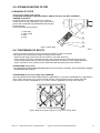
RS 6-35 INSTALLATION AND MAINTENANCE MANUAL PUBLICATION DATE: 20 Feb 2008 504615 F INDUSTRIAL WASHER-EXTRACTORS RS 6/7/10/13/18/22/27/35 1. CONTENTS Publication date 20 Feb 2008 Page: 1. CONTENTS..................................................................................................................... 1 2. WARNINGS AND SYMBOLS ......................................................................................... 2 2.1. PERSONAL SAFETY RULES .................................................................................................................2 2.2. SYMBOLS ON THE MACHINE ...............................................................................................................2 2.3. IMPORTANT INFORMATION BEFORE INSTALLATION.......................................................................3 3. TECHNICAL INFORMATION.......................................................................................... 4 3.1. TECHNICAL SPECIFICATIONS 6/7/10/13 kg - 15/18/25/30 lb CAPACITY...................................................4 3.2. TECHNICAL SPECIFICATIONS 18/22/27/35 kg - 40/50/60/80 lb CAPACITY .................................................6 3.3. DIMENSIONS AND COMPONETS OF THE MACHINE................................................................................8 4. INSTALLATION OF THE MACHINE............................................................................. 10 4.1. HANDLING, TRANSPORT, STORAGE AND UNPACKING .................................................................10 4.2. SPACE REQUIREMENTS.....................................................................................................................10 4.3. MACHINE'S POSITIONING...................................................................................................................10 4.4. CONNECTIONS ....................................................................................................................................13 4.5. PUTTING INTO SERVICE.....................................................................................................................17 5. MAINTENANCE ............................................................................................................ 18 5.1. INTRODUCTION ...................................................................................................................................18 5.2. DAILY.....................................................................................................................................................18 5.3. EVERY THREE MONTHS.....................................................................................................................18 5.4. EVERY SIX MONTHS ...........................................................................................................................18 5.5. STEAM OR WATER FILTER.................................................................................................................19 5.6. TIGHTENING OF BOLTS ......................................................................................................................19 5.7. DOOR SEAL ..........................................................................................................................................20 5.8. BELTS OF DRIVE..................................................................................................................................21 5.9. FUSES ...................................................................................................................................................24 6. TROUBLE SHOOTING AIDS........................................................................................ 25 6.1. EMERGENCY DOOR OPENING ..........................................................................................................25 6.2. FILLING TIME TOO LONG....................................................................................................................25 6.3. HEATING TIME TOO LONG .................................................................................................................25 6.4. DRAIN TIME TOO LONG ......................................................................................................................25 6.5. PROGRAMMER PROBLEMS ...............................................................................................................25 7. LIST OF RECOMMENDED SPARE PARTS................................................................. 26 8. PUTTING THE MACHINE OUT OF SERVICE.............................................................. 27 8.1. DISCONNECTING THE MACHINE.......................................................................................................27 8.2. MACHINE LIQUIDATION ......................................................................................................................27 504615 F PUBLICATION DATE 20 FEB 2008.DOC INSTALLATION AND MAINTENANCE MANUAL 1 2. WARNINGS AND SYMBOLS TO MINIMIZE THE RISK OF FIRE, INJURY BY ELECTRIC SHOCK OR SERIOUS INJURIES OF PERSONS OR PROPERTY DAMAGE, PLEASE READ AND FOLLOW THE FOLLOWING INSTRUCTIONS: 2.1. PERSONAL SAFETY RULES GENERALLY • This English version is the original version. • This instruction is not complete without „User’s“, „Programming“, and „Spare parts manual“. • Before installation, operation and maintenance of the machine read carefully the complete instructions supplied with the machine, i.e. this „Installation and maintenance manual“, „User’s manual“, „Programming manual“ and „Instruction manual for frequency inverter“. Keep the manuals in a handy place. • Do not bypass the safety instructions stated in manuals and warnings on the labels. Basic safety instructions stated in chapters „2. Warnings and symbols“ of the supplied manuals should be printed and located near the machine for the operator's use. The labels must be readable and permanently located on the machine! • Follow all valid local safety instructions and laws ! • Do not use the machine with its parts damaged, missing parts or opened covers ! • Do not store any flammable materials near the machine. Storing of chemicals near the machine or operating dry cleaning machines in bad technical conditions can cause a health damage or the machine parts corrosion. • Do not tamper with the machine controls. • The washer extractor is intended to be permanently connected to fixed wiring. • The machine must be connected to the power, ground, water, ventilation and steam supply according to the installation manual, in compliance with the local standards done by qualified technicians with proper authorization. The valid standards for connecting to the local power network (TT / TN / IT, ...) must be followed. In the standard execution, the washer may not be suitable for connecting to an IT supply system. • If you have a machine with frequency inverter do not change the parameters of the inverter. Doing so can cause serious injury, fire, machine damage, etc. • Instructions and warnings included in this manual do not cover all possible conditions and situations that can occur at installation, maintenance or operations of the machine. They must be understand in common sense. Caution and carefulness are factors that can not be achieved by the design of machine. These factors are conditioned by qualification and competence of personnel who install, operate and maintain the machine. • In case of a problem or situations that you can not solve by yourselves, contact your qualified serviceman, manufacturer or the dealer. Always state the model and serial number of your machine from the completed last page of the manual. • The emergency stop device is omitted on machines design for coin, token, external payment system or similar operation for use in self-service situation. The owner-installer-user must provide a remote-located emergency stop device that is connected to each machine. FOR MAINTENANCE • When the main switch is off, the inlet terminals of the switch are still under current! • Do not bypass any safety devices or their parts. Any interference to the machine function and design are prohibited and the manufacturer does not bear any responsibilities in such cases! • Before maintenance activities always disconnect the machine power supply! • Do not repair or replace any machine parts and do not perform machine service work if it is not recommended in the maintenance instructions. All other service activities should be provided by qualified service workers. • Do not repair or adjust the machine belt drives while in operation. Turn off the main switch! • Original or identical parts must be used for replacement in this machine. After servicing replace and secure all panels in the original way. Take these measures for continued protection against electrical shock, injury, fire and/or property damage. • Once in 3 months, check the earthing and the emergency function. • Keep the machine top clean and free of flammable materials. Do not wash or spray the machine by water. • For the steam heated version: In case of steam leakage, shut-off the main valve of steam supply and call the maintenance worker. INSTALLATION AND SERVICE CAN BE DONE BY A SERVICE ORGANIZATION WITH PROPER AUTHORIZATION FROM THE MANUFACTURER. The machine warranty can be cancelled if the instructions of this manual are not followed. 2.2. SYMBOLS ON THE MACHINE Danger, read and follow written instructions Caution, high power voltage, electrical devices Press push button in case of emergency 2 INSTALLATION AND MAINTENANCE MANUAL 504615 F PUBLICATION DATE 20 FEB 2008.DOC 2.3. IMPORTANT INFORMATION BEFORE INSTALLATION FOR TRANSPORTATION AND STORAGE IN CASE OF TRANSPORTATION AND STORAGE, WATCH COMPONENTS PROTRUDING FROM THE CONTOUR LINE OF MACHINE (DOOR LOCKS ETC.), TO AVOID INJURIES. • Never push, pull or exert pressure on components protruding from the machine contour line (controls, door locks etc.). • Make sure that these components are secured so as to avoid damages during machine manipulation and installation. • In case of the machine transportation by the customer, follow the manufacturer's instructions for transportation, handling and storage of the product. In case of transportation of machine by the customer the manufacturer is not responsible for possible damage of machine in the course of transportation. • The ambient temperature of transportation and storage must be between -25°C - +55°C. Relative humidity must be between 30% - 90% without condensation. In case of storage the machine in a free area it must be protected against mechanical damage and weather condition factors. FOR INSTALLATION ELECTRICAL CONNECTION, EARTHING AND VENTING OF THE MACHINE, WATER INLETS AND DRAINAGE MUST BE PERFORMED BY QUALIFIED PERSONNEL WITH A PROPER AUTHORIZATION ACCORDING THE INSTALLATION MANUAL IN COMPLIANCE WITH LOCAL STANDARDS (APPLICABLE ALSO FOR STEAM CONNECTION ON STEAM HEATED MACHINES). • Do not install the machine at places exposed to climatic effects or excessive humidity. The machine is not designed to accept environment with sprayed water. • Any changes in the machine installations must be approved by dealer or manufacturer. Otherwise the dealer/manufacturer is not responsible for possible injuries or damages. Interference and changes in the machine construction are not allowed and the manufacturer refuses any responsibilities in such cases. • Define dangerous areas in the laundry room and do not allow people to enter if the machine is in operation. MACHINE VERSION • This manual contain information for the whole series of rigid mounted machine types with filling of dry linen 6, 7, 10, 13, 18, 22, 27 and 35 kg (15, 18, 25, 30, 40, 50, 60 and 80 lb). Check, please, the type of your machine on the production label (located on back of machine) and look for right information in the manual. • Machines are equipped with electronic programmer. The „OPL“ is a version with a programmer controlled only by push-buttons without coin meter. • Motor is controlled by frequency inverter. • Starting of the machine comes by an automatic coin slot or a start push-button. • Heating is provided by electrical heating elements or by steam from your steam system. • Water valves are used for cold hard, cold soft and if necessary warm water. • The machine electrical connection is single-phase 1AC/220V, three-phases 3AC/220V or three-phases 3AC/380-415V. Machines in accordance to CE directives are „CE“ marked on the machine name plate. • The machine design which fulfils The European Agreement requirements is stated in the name plate by the symbol „CE“. • All machines types are produced according the EMC-directive (Electro-Magnetic-Compatibility). They can be used in restricted surroundings only (comply minimally with class A requirements). For safety reasons there must be kept the necessary precaution distances with sensitive electrical or electronic device(s). • The product fulfils the technical requirements for a product determined by the law no. 22 / 1997 of Digest of Czech Republic. • The used electrical standard for concerned machines covered by this manual depends on the scope of the considered standards in which the machine best fits. The chosen electrical standard is mentioned in the declaration of conformity that is delivered by each machine. 504615 F PUBLICATION DATE 20 FEB 2008.DOC INSTALLATION AND MAINTENANCE MANUAL 3 3. TECHNICAL INFORMATION 3.1. TECHNICAL SPECIFICATIONS 6/7/10/13 kg - 15/18/25/30 lb CAPACITY 6 kg / 15 lb CAPACITY 7 kg / 18 lb 10 kg / 25 lb 13 kg / 30 lb DIMENSIONS PACKING: width depth height transportation capacity MACHINE: width depth height INNER DRUM: diameter depth drum capacity door opening Netto Brutto 140 kg / 309 lb 145 kg / 320 lb * carton box 700 mm / 27.6“ 730 mm / 28.7“ 1180 mm / 46.5“ 0.6m3 / 21.2 ft3 carton box 700 mm / 27.6“ 730 mm / 28.7“ 1180 mm / 46.5“ 0.6m3 / 21.2 ft3 carton box 700 mm / 27.6 „ 880 mm / 34.6“ 1280 mm / 50.4“ 0.79m3 / 27.9 ft3 carton box 810 mm / 31.9“ 850 mm / 33.5“ 1380 mm / 54.3“ 0.95m3 / 33.6 ft3 660 mm / 26“ 710 mm / 28“ 1045 mm / 41.1“ 660 mm / 26“ 710 mm / 28“ 1045 mm / 41.1“ 660 mm / 26“ 865 mm / 34“ 1140 mm / 44.9“ 750 mm / 29.5“ 820 mm / 32.3“ 1225 mm / 48.2“ 530 mm / 21“ 270 mm / 10.6“ 60 dm3 / 15.8 gal 290 mm / 11.4“ 530 mm / 21“ 330 mm / 13“ 73 dm3 / 19.3 gal 290 mm / 11.4“ 530 mm / 21“ 420 mm / 16.5“ 95 dm3 / 25 gal 290 mm / 11.4“ 650 mm / 25.6“ 395 mm / 15.6“ 131 dm3 / 34.6 gal 410 mm / 16.1“ 185 kg / 408 lb 195 kg / 430 lb 195 kg / 430 lb 205 kg / 452 lb WEIGHT 140 kg / 309 lb 145 kg / 320 lb ELETRICAL DATA Permitted deviations of feeding voltage Permitted deviations of frequence Electrical system of the machine -6% to +10%V ±1% Hz 1x220-240V 50/60Hz - not applicable for electrical heating 1x208-240V 50/60Hz - not applicable for electrical heating 1x220V 50/60Hz - not applicable for electrical heating 3x220-240V 50/60Hz 3x208-240V 50/60Hz 3x200V 50/60Hz 3x380-415V+N 50/60Hz 3x380-480V 50/60Hz Minimal power supply 342V / 180V voltage NOMINAL OUTPUT 0.6 kW OF THE MOTOR AT RPM INPUT PROTECTION FOR ONE MACHINE Electrical heating 6kW / 3x220-240V / 20A 6kW / 3x400V / 16A 9kW / 3x220-240V / 32A 9kW / 3x400V / 20A 9kW / 3x440V / 16A Without electrical heating 1x220-240V / 10A 3x220-240V / 10A 3x400V / 10A 3x440V / 10A 342V / 180V 345V / 180V 342V / 190V 0.6 kW 0.6 kW 0,75 kW 6kW / 3x220-240V / 20A 6kW / 3x400V / 16A 9kW / 3x220-240V / 32A 9kW / 3x400V / 20A 9kW / 3x440V / 16A 6kW / 3x220-240V / 20A 6kW / 3x400V/16A 9kW / 3x220-240V / 32A 9kW / 3x400V/20A 9kW / 3x440V/16A 12kW / 3x220-240V / 40A 12kW / 3x400V / 25A 12kW / 3x440V / 25A 6kW/3x220-240V/ 20A 6kW/3x400V/16A 9kW/3x220-240V/ 32A 9kW/3x400V/20A 9kW/3x440V/20A 12kW/3x220-240V/ 40A 12kW/3x400V/25A 12kW/3x440V/25A 1x220-240V / 10A 3x220-240V / 10A 3x400V / 10A 3x440V / 10A 1x220-240V / 10A 3x220-240V / 10A 3x400V / 10A 3x440V / 10A 1x220-240V / 10A 3x220-240V / 10A 3x400V / 10A 3x440V / 10A Overload protection electronic protection by the frequency inverter of the motor maximum dimensions including protruding parts Tab.3.1. * 4 INSTALLATION AND MAINTENANCE MANUAL 504615 F PUBLICATION DATE 20 FEB 2008.DOC CAPACITY 6 kg / 15 lb 7 kg / 18 lb 10 kg / 25 lb 13 kg / 30 lb WASHING FUNCTION RPM OF THE DRUM: washing extracting G - factor of spinning 48 rpm 580 rpm 45 rpm 525 rpm 100 CONNECTIONS WATER CONNECTION Water pressure Recommended water pressure Water inlet Maximal water temperature 0.1 - 0.8 MPa / 1 - 8 bar / 14.5 -116 PSI 0.3 - 0.5 MPa / 3 - 5 bar / 43 - 73 PSI BSP 3/4“ 90°C / 194°F DRAIN CONNECTION Dimension Capacity STEAM CONNECTION Steam connection Steam pressure low Steam pressure high Connections to external liquid soap supply Soap hoppers 76 mm / 3“ 3.5 l / s G1/2“ 1 - 3 bar / 14.5 - 44 PSI 3 - 8 bar / 44 - 116 PSI standard 6 pcs, (see electrical scheme) 3 CONSUMPTION STEAM Average steam consumption (depends on selected programme) Maximum steam consumption 6 kg. cycle -1 / 13.2 lb. cycle -1 7 kg. cycle -1 / 15.4 lb. cycle -1 0.01 kg.s-1 / 36 kg.h-1 0.02 lb.sec-1 / 79 lb.h-1 0.01 kg.s-1 / 36 kg.h-1 0.02 lb.sec-1 / 79 lb.h-1 10 kg. cycle -1 / 22 lb. cycle -1 13 kg. cycle -1 / 28.7 lb. cycle -1 0.011 kg.s-1 / 40 kg.h-1 0.016kg.s-1/ 57.6kg.h-1 0.024 lb.sec-1 / 88 lb.h-1 0.031lb.sec-1/ 111.6lb.h-1 WORKING CONDITIONS Ambient temperature Relative humidity Height above sea level Storage temperature + 5°C (41°F) to + 35°C (95°F) 30% to 90% without condensation up 1000 m / 3280 ft 0°C (32°F) to +55°C (131°F) ANCHORING Bolt FLOOR DATA Max. static floor load Max. dynamic floor load Frequency of dynamic load 6 pcs M16 x 160 1.7 kN / 370 lb 3.6 kN / 801 lb 1.7 kN / 370 lb 3.6 kN / 801 lb 2.1 kN / 474 lb 4.5 kN / 1020 lb 2.6 kN / 577 lb 6.5 kN / 1450 lb 9.67 Hz 9.67 Hz 9.67 Hz 8.75 Hz NOISE Sound level Leq (dB(A)) < 70 dB(A) Tab.3.1. continuation 504615 F PUBLICATION DATE 20 FEB 2008.DOC INSTALLATION AND MAINTENANCE MANUAL 5 3.2. TECHNICAL SPECIFICATIONS 18/22/27/35 kg - 40/50/60/80 lb CAPACITY 18 kg / 40 lb CAPACITY 22 kg / 50 lb 27 kg / 60 lb 35 kg / 80 lb DIMENSIONS PACKING: width depth height transportation capacity MACHINE: width depth height INNER DRUM: diameter depth drum capacity door opening * carton box 935 mm / 36.8“ 955 mm / 37.6“ 1530 mm / 60.2“ 1.37 m3 / 48.4 ft3 carton box 935 mm / 36.8“ 1050 mm / 41.3“ 1530 mm / 60.2“ 1.5 m3 / 53 ft3 wooden crate 950 mm / 37.4“ 1220 mm / 48“ 1570 mm / 61.8“ 1.82 m3 / 64.3 ft3 wooden crate 1150 mm / 45.3“ 1200 mm / 47.2“ 1630 mm / 64.2“ 2.25 m3 / 79.4 ft3 855 mm / 33.7“ 900 mm / 35.43“ 1315 mm / 51.8“ 855 mm / 33.7“ 1000 mm / 39.37“ 1315 mm / 51.8“ 870 mm / 34.3“ 1140 mm / 44.9“ 1380 mm / 54.3“ 1100 mm / 43.7“ 1140 mm / 44.9“ 1460 mm / 57.5“ 700 mm / 27.6“ 470 mm / 18.5“ 181 dm3 / 47.8 gal 410 mm / 16.1“ 700 mm / 27.6“ 565 mm / 22.4“ 217 dm3 / 57.3 gal 410 mm / 16.1“ 750 mm / 29.5“ 610 mm / 24“ 269 dm3 / 71 gal 504 mm / 19.8“ 914 mm / 36“ 505 mm / 19.9“ 355 dm3 / 93.7 gal 504 mm / 19.8“ 410 kg / 904 lb 470 kg / 1036 lb 710 kg / 1565 lb 740 kg / 1631 lb WEIGHT 280 kg / 617 lb 290 kg / 639 lb Netto Brutto 280 kg / 617 lb 300 kg / 661 lb ELETRICAL DATA Permitted deviations of feeding voltage Permitted deviations of frequence Electrical system of the machine -6% to +10%V ±1% Hz 1x220-240V 50/60Hz - not applicable for electrical heating 3x220-240V 50/60Hz 3x380-415V+N 50/60Hz 3x380-480V 50/60Hz Minimal power supply voltage NOMINAL OUTPUT OF THE MOTOR AT RPM INPUT PROTECTION FOR ONE MACHINE Electrical heating Without electrical heating 342V / 190V 342V / 190V 342V / 190V 342V / 190V 1.5 kW 1.5 kW 2.2 kW 3 kW 12kW / 3x220-240V / 50A 12kW / 3x 400V+N / 32A 12kW / 3x400V / 25A 12kW / 3x440V / 25A 18kW / 3x220-240V / 63A 18kW / 3x 400V+N / 40A 18kW / 3x400V / 32A 18kW / 3x440V / 32A 18kW / 3x220-240V / 63A 18kW / 3x 400V+N / 40A 18kW / 3x400V / 40A 18kW / 3x440V / 32A 24kW / 3x220-240V / 80A 24kW / 3x 400V+N / 50A 24kW / 3x400V / 50A 24kW / 3x440V / 50A 1/3x220-240V / 16A 3x400V+N / 16A 3x400V / 10A 3x440V / 10A 1/3x220-240V / 20A 3x400V+N / 20A 3x400V / 16A 3x440V / 16A Overload protection electronic protection by the frequency inverter of the motor maximum dimensions including protruding parts Tab.3.2. * 6 INSTALLATION AND MAINTENANCE MANUAL 504615 F PUBLICATION DATE 20 FEB 2008.DOC CAPACITY 18 kg / 40 lb 22 kg / 50 lb 27 kg / 60 lb 35 kg / 80 lb 42 rpm 490 rpm 100 38 rpm 510 rpm 133 WASHING FUNCTION RPM OF THE DRUM: washing extracting G - factor of spinning 44 rpm 505 rpm 100 44 rpm 480 rpm 90 CONNECTIONS WATER CONNECTION Water pressure Recommended water pressure Water inlet Maximal water temperature DRAIN CONNECTION Dimension Capacity STEAM CONNECTION Steam connection Steam pressure low Steam pressure high Connections to external liquid soap supply Soap hoppers 0.1 - 0.8 MPa / 1 - 8 bar / 14.5 -116 PSI 0.3 - 0.5 MPa / 3 - 5 bar / 43 - 73 PSI BSP 3/4“ 90°C / 194°F 76 mm / 3“ 3.5 l / s 2 x 76 mm / 2x3“ 2 x 3.5 l / s G1/2“ G3/4“ 1 - 3 bar / 14.5 - 44 PSI 1 - 3 bar / 14.5 - 44 PSI 3 - 8 bar / 44 - 116 PSI 3 - 8 bar / 44 - 116 PSI standard 6 pcs, (see electrical scheme) 3 CONSUMPTION STEAM Average steam consumption (depends on selected programme) Maximum steam consumption 18 kg. cycle -1 / 40 lb. cycle -1 22 kg. cycle -1 / 49 lb. cycle -1 27 kg. cycle -1 / 60 lb. cycle -1 35 kg. cycle -1 / 77 lb. cycle -1 -1 -1 -1 -1 -1 -1 0.021 kg.s-1 / 76 kg.h-1 0.025 kg.s / 90 kg.h 0.032 kg.s / 115 kg.h 0.039 kg.s / 140 kg.h -1 -1 -1 -1 -1 -1 -1 0.038 lb.sec / 137 lb.h 0.055 lb.sec / 199 lb.h 0.071 lb.sec / 256 lb.h 0.086 lb.sec / 309 lb.h-1 WORKING CONDITIONS Ambient temperature Relative humidity Height above sea level Storage temperature + 5°C (41°F) to + 35°C (95°F) 30% to 90% without condensation up 1000 m / 3280 ft 0°C (32°F) to +55°C (131°F) ANCHORING Bolt FLOOR DATA Max. static floor load Max. dynamic floor load Frequency of dynamic load 6 pcs M16 x 160 6 pcs M20 x 320 3.1 kN / 675 lb 8.9 kN / 1994 lb 3.2 kN / 698 lb 9.6 kN / 2165 lb 4.5 kN / 985 lb 13.3 kN / 2996 lb 7.2 kN / 1598 lb 21.6 kN / 4863 lb 8.42 Hz 8 Hz 8.17 Hz 8.5 Hz NOISE Sound level Leq (dB(A)) < 70 dB(A) Tab.3.2. continuation 504615 F PUBLICATION DATE 20 FEB 2008.DOC INSTALLATION AND MAINTENANCE MANUAL 7 3.3. DIMENSIONS AND COMPONETS OF THE MACHINE 18/22/27 kg - 40/50/60 lb 6/7/10/13 kg - 15/18/25/30 lb only for 27 kg / 60 lb 35 kg / 80 lb Fig.3.3. 8 INSTALLATION AND MAINTENANCE MANUAL 504615 F PUBLICATION DATE 20 FEB 2008.DOC 1. Control panel 2. Door handle 3. Service panel 4. Air vent 5. Liquid soap hose connections 6. Name plate 7. Steam connection 8. Drain connection 9. Earthing connection 10. Hot water connection Machine capacity 6 kg 15 lb 7 kg 18 lb 11. Cold soft water connection 12. Cold hard water connection 13. Fuses 14. Main switch 15. Switch: electrical heating / steam heating 16. Electrical connection of machine 17. Electrical connection to liquid soap pumps 18. Soap hoppers 19. Keyswitch: run mode / programming mode 10 kg 25 lb 13 kg 30 lb 18 kg 40 lb 22 kg 50 lb 27 kg 60 lb K 660 mm 26“ 1045 mm 41.1“ 420 mm 16.5“ 710 mm 28“ 620 mm 24.4“ 100 mm 3,9“ 86 mm 3.4“ 90 mm 3.5“ 190 mm 7.5“ 75 mm 3“ 660 mm 26“ 1045 mm 41.1“ 420 mm 16.5“ 710 mm 28“ 620 mm 24.4“ 100 mm 3,9“ 86 mm 3.4“ 90 mm 3.5“ 190 mm 7.5“ 75 mm 3“ 660 mm 26“ 1140 mm 44.9“ 460 mm 18.1“ 865 mm 34“ 780 mm 30.7“ 100 mm 3,9“ 86 mm 3.4“ 90 mm 3.5“ 190 mm 7.5“ 75 mm 3“ 750 mm 29.5“ 1225 mm 48.2“ 420 mm 16.5“ 820 mm 32.3“ 740 mm 29.1“ 100 mm 3,9“ 86 mm 3.4“ 90 mm 3.5“ 190 mm 7.5“ 75 mm 3“ 855 mm 33.7“ 1315 mm 51.8“ 515 mm 20.3“ 900 mm 35.43“ 810 mm 31.9“ 125 mm 4.9“ 90 mm 3.5“ 100 mm 3.9“ 190 mm 7.5“ 75 mm 3“ 855 mm 33.7“ 1315 mm 51.8“ 515 mm 20.3“ 1000 mm 39.37“ 905 mm 35.6“ 125 mm 4.9“ 90 mm 3.5“ 100 mm 3.9“ 190 mm 7.5“ 75 mm 3“ 870 mm 34.3“ 1380 mm 54.3“ 455 mm 17,9“ 1140 mm 44.9“ 1043 mm 41.1“ 160 mm 6.3“ 85 mm 3.3“ 90 mm 3.5“ 190 mm 7.5“ 70 mm 2.8“ L - - - - - - - M N 270 mm 10.6“ 60 mm 2.4“ 270 mm 10.6 60 mm 2.4“ 270 mm 10.6 60 mm 2.4“ 270 mm 10.6 60 mm 2.4“ 305 mm 12“ 75 mm 3“ 305 mm 12“ 75 mm 3“ 260 mm 10.2“ 170 mm 6.7“ O - - - - - - - P V 970 mm 38.2“ 133 mm 5.2“ 875 mm 34.4“ 55 mm 2.2“ 395 mm 15.6“ 92 mm 3.6“ 330 mm 13“ 970 mm 38.2“ 133 mm 5.2“ 875mm 34.4 55 mm 2.2“ 395 mm 15.6“ 92 mm 3.6“ 330 mm 13“ 1062 mm 41.8“ 133 mm 5.2“ 962 mm 37.9“ 55 mm 2.2“ 395 mm 15.6 92 mm 3.6“ 330 mm 13“ 1145 mm 45.1“ 182 mm 7.2“ 1025 mm 40.4“ 53 mm 2.1“ 333 mm 13.1“ 86 mm 3.4“ 375 mm 14.8“ 1215 mm 47,8" 205 mm 8.1“ 1110 mm 43.7" 100 mm 3.9" 435 mm 17.1" 135 mm 5.3“ 427,5 mm 16.8“ 1215 mm 47,8" 205 mm 8.1“ 1110 mm 43.7" 100 mm 3.9" 435 mm 17.1" 135 mm 5.3“ 427,5 mm 16.8“ 1245 mm 49“ 120 mm 4.7“ 1135 mm 44.7" 135 mm 5.3" 470 mm 18.5" 90 mm 3.5“ 435 mm 17.1“ W - - - - - - - X 106 mm 4.2“ 415 mm 16.3“ 350 mm 13,8“ 106 mm 4.2“ 415 mm 16.3“ 350 mm 13,8“ 106 mm 4.2“ 415 mm 16.3“ 390 mm 15,4“ 175 mm 6.9“ 530 mm 20.8“ 355 mm 13,98“ 203 mm 8“ 530 mm 20.8“ 450 mm 17,7“ 203 mm 8“ 530 mm 20.8“ 450 mm 17,7“ 195 mm 7.7“ 630 mm 24.8“ 380 mm 14,96“ A B C D E F G H J Q R S T U Y Z 35 kg 80 lb 1100 mm 43.3“ 1460 mm 57.5“ 510 mm 20.1“ 1140 mm 44.9“ 1041 mm 41“ 125 mm 4.9“ 85 mm 3.3“ 100 mm 3.9“ 195 mm 7.7“ 124 mm 4.9“ 360 mm 14.2“ 305 mm 12“ 355 mm 14“ 84 mm 3.3“ 1320 mm 51,9" 250 mm 9.8“ 1220 mm 48.3" 100 mm 3.9" 972 mm 38.3" 90 mm 3.5“ 400 mm 15.7" 300 mm 11.8“ 245 mm 9.7“ 630 mm 24.8“ 430 mm 16,9“ Tab.3.3. 504615 F PUBLICATION DATE 20 FEB 2008.DOC INSTALLATION AND MAINTENANCE MANUAL 9 4. INSTALLATION OF THE MACHINE 4.1. HANDLING, TRANSPORT, STORAGE AND UNPACKING Only a qualified person can handle or operate the machine. STORAGE The machine is delivered to the customer in a cardboard packing (only for machines with capacity 6 to22 kg / 15 to 50 lb), wooden box or wooden-lath packaging and the machine is additionally protected by polyethylene foil. Do not store or install the machine where it can be exposed to environmental conditions (rain, wind) or extreme humidity. HANDLING DURING INSTALLATION All activities can be done only by a worker, which knows all information about the machine. The machine is fixed to the wooden palette by four bolts M12x60, (M10x45, applicable for 6/7/10 kg - 15/18/25 lb). To remove the machine to its final location follow these precautions: • Check all passages and spaces where the machine has to be transported through, they must have sufficient dimensions to meet the height and width of the machine including the package. • Never push, pull or press the components protruding from the contour line of machine (front part, filling door, control elements, belt cover, water inlet and outlet pipes etc.). MAKE SURE THAT THESE COMPONENTS ARE PROTECTED, TO AVOID THEIR DAMAGE DURING HANDLING AND INSTALLATION OF THE MACHINE. • Make sure that the filling door are secured to avoid its opening during the handling. • Lift the machine up by lift truck or hand-operated pallet truck using a transport skid to which the machine has been attached. UNPACKING Before you install the machine in its place, remove the package, release four bolts and lift up the machine using the high lift truck and remove the wooden palette. It is possible to handle the machine by the fork lift or the manual truck in such a way, so that the forks would not damage the components located in its lower part. After unpacking, check if the machine has not been damaged and if all the accessories are included according to your order. Verify the type of your machine by a name plate located on the machine rear and find corresponding information in the manual. The accessories and the manual are placed inside the drum, which can be opened according to chapter 6.1. 4.2. SPACE REQUIREMENTS REQUIRED MACHINE WORKING CONDITIONS See chapter „3. TECHNICAL SPECIFICATION“. The machine may not be installed within the reach of directly spraying water. Do not install the machine where it will be exposed to weather condition and excessive humidity. When steamed up due to temperature changing, water must not run over the machine walls and covers, nor to cover the floor under and around it. REQUIRED ROOM DIMENSIONS Provided that the requirements in respect to room dimensions are not met, the maintenance of the machine may be difficult. Leave at least a 0.6 m / 23.6“ free space between the rear panel of machine and the wall. Leave at least a 0.04 m / 1.57“ free space between the side panel of machine and the wall or other machine and 0.1 m / 4“ for 27kg / 60 lb, 35 kg / 80 lb version. Leave at least a 0.7 m / 27.6“, 1 m / 39“ for 27kg / 60 lb, 35 kg / 80 lb version free space between the top panel of machine and the ceiling, which cannot be dismantled (see fig.4.3.E.,dimension „J“). 4.3. MACHINE'S POSITIONING MACHINE'S POSITIONING ON THE FLOOR The machines must always be fixed to the floor which complies with static and dynamic machine stress. There are two systems possible. The machine can be fixed to a concrete socle by bolts (see fig.4.3.A, pos.1). It can also be bolted on a metal socle (fig.4.3.B, pos.9) which is fixed to the floor by bolts. The manufacturer recommends to fix machines of the 18 kg / 40 lb and 22 kg / 50 lb type to the base of height 18 cm / 7“ for easier manipulation with the linen. For 27 kg / 60 lb, 35 kg / 80 lb machine concrete base must be built with 50 cm / 19.7“ total height and 20 cm / 8“ under the floor level. For 18 kg / 40 lb and 22 kg / 50 lb type: In case there are gaps between the frame of the machine and the concrete or metal socle before tightening the bolts, use the shims delivered with the machine (see fig.4.3.A., fig.4.3.B., pos.7) to fill this gaps. 10 INSTALLATION AND MAINTENANCE MANUAL 504615 F PUBLICATION DATE 20 FEB 2008.DOC Fig.4.3.A Fig.4.3.B Fig.4.3.C Position of foundation bolts for machines 6 kg / 15 lb to 22 kg / 50 lb 1. Foundation bolt 2. Nut 3. Machine socle 4. Washer 5. Concrete base Fig.4.3.D Position of foundation bolts for machine 27 kg / 60 lb, 35 kg / 80 lb 6. Existing floor 7. Shim for machine type 18 kg / 40 lb and 22 kg / 50 lb type 8. Bolt 9. Metal socle Fig.4.3.E Base description 504615 F PUBLICATION DATE 20 FEB 2008.DOC INSTALLATION AND MAINTENANCE MANUAL 11 Machine capacity A B C D E F G H I min. J min. K L M min. N O P 6-7 kg 15-18 lb 530 mm 20.9“ 65 mm 2.6“ 100 mm 4“ 40 mm 1.57“ 86 mm 3.4“ 275 mm 10.8“ 90 mm 3.5“ 169 mm 6.7“ 600 mm 23.6“ 700 mm 27.6“ 40 mm 1.6“ 120 mm 4.7“ 300 mm 11.8“ 50 mm 2“ 135 mm 5.3“ M16 x 160 10 kg 25 lb 530 mm 20.9“ 65 mm 2.6“ 100 mm 4“ 40 mm 1.57“ 86 mm 3.4“ 365 mm 14.4“ 295 mm 11.6“ 34 mm 1.3“ 600 mm 23.6“ 700 mm 27.6“ 40 mm 1.6“ 120 mm 4.7“ 300 mm 11.8“ 50 mm 2“ 135 mm 5.3“ M16 x 160 13 kg 30 lb 594 mm 23.4“ 78 mm 3.1“ 100 mm 4“ 40 mm 1.57“ 68 mm 2.7“ 400 mm 15.8“ 232 mm 9.1“ 40 mm 1.6“ 600 mm 23.6“ 700 mm 27.6“ 40 mm 1.6“ 120 mm 4.7“ 400 mm 15.7“ 50 mm 2“ 140 mm 5.6“ M16 x 160 18 kg 40 lb 700 mm 27.6“ 77,5 mm 3.1“ 100 mm 4“ 40 mm 1.57“ 110 mm 4.3“ 360 mm 14.2“ 295 mm 11.6“ 90 mm 3.5“ 600 mm 23.6“ 700 mm 27.6“ 40 mm 1.6“ 120 mm 4.7“ 400 mm 15.7“ 50 mm 2“ 140 mm 5.6“ M16 x 160 22 kg 50 lb 700 mm 27.6“ 77,5 mm 3.1“ 100 mm 4“ 40 mm 1.57“ 110 mm 4.3“ 500 mm 19.7“ 251 mm 9.9“ 90 mm 3.5“ 600 mm 23.6“ 700 mm 27.6“ 40 mm 1.6“ 120 mm 4.7“ 400 mm 15.7“ 50 mm 2“ 140 mm 5.6“ M16 x 160 27 kg 60 lb 636 mm 25“ 117 mm 4.6“ 100 mm 4“ 100 mm 4“ 91 mm 3.6“ 675 mm 26.6“ 230 mm 9.1“ 47 mm 1.9“ 600 mm 23.6“ 1000 mm 39.4“ 80 mm 3.15“ 240 mm 9.4“ 500 mm 19.7“ 50 mm 2“ 190 mm 7.5“ M20 x 320 35 kg 80 lb 820 mm 32.3“ 140 mm * 5.5“ 100 mm 4“ 100 mm 4“ 131 mm 5.2“ 295 mm 11.6“ 565 mm 22.2“ 52 mm 2.1“ 600 mm 23.6“ 1000 mm 39.4“ 80 mm 3.15“ 240 mm 9.4“ 500 mm 19.7“ 50 mm 2“ 190 mm 7.5“ M20 x 320 * for machine 27 kg / 60 lb, 35 kg / 80 lb build the concrete base with „N“ dimension bigger than the machine contour Tab.4.3. Dimensions of machine 12 INSTALLATION AND MAINTENANCE MANUAL 504615 F PUBLICATION DATE 20 FEB 2008.DOC 4.4. CONNECTIONS ELECTRICAL CONNECTION GENERAL WARNING ! ! THE MACHINE MUST BE CONNECTED TO THE POWER, GROUND, WATER, VENTILATION AND STEAM SUPPLY ACCORDING TO THE INSTALLATION MANUAL, IN COMPLIANCE WITH THE VALID LOCAL STANDARDS DONE BY QUALIFIED TECHNICIANS WITH PROPER AUTHORIZATION. THE VALID STANDARDS FOR CONNECTING TO THE LOCAL POWER NETWORK (TT / TN / IT, ...) MUST BE FOLLOWED. IN THE STANDARD EXECUTION, THE WASHER MAY NOT BE SUITABLE FOR CONNECTING TO AN IT SUPPLY SYSTEM. THE WASHER EXTRACTOR IS INTENDED TO BE PERMANENTLY CONNECTED TO THE ELECTRICAL SUPPLY. The machines have been designed for connecting to the electrical network according to the specifications of your order. Before connection check if the electrical values stated on the serial plate of the machine correspond to your electrical network. If not do not connect the machine, please contact your dealer. If the machine is not equipped with a supply disconnecting device, like a main switch then a supply disconnecting device need to be provided in the installation for all electrical supplies connected to the machine, in accordance with EN 60204-1 standard, point 5.3. This device shall disconnect the electrical equipment of the machine from the supply when required e.g. maintenance. EMERGENCY STOP DEVICE The machines are equipped with an emergency stop device in accordance with ISO13850 - category 0 stop function. Nevertheless, the emergency stop device is omitted on machines design for coin, token, external payment system or similar operation for use in self-service situation. The owner-installer-user must provide remote-located emergency stop device(s). This emergency stop device(s) needs to stop each machine in accordance with ISO13850 - category 0. There are made provisions in the wiring harness, were immediate removal of power to the actuators can be accomplished. See the electrical schematic of the machine for correct connection of the device. SUPPLY CABLE AND SAFETY DEVICES MACHINE Fig. 4.4.A. Example of electrical connection 504615 F PUBLICATION DATE 20 FEB 2008.DOC INSTALLATION AND MAINTENANCE MANUAL 13 Supply cable of the machine must have copper wires. The cross section of the supply wires depends on the supply voltage and on the total electrical power input of the machine (see table 3.1., 3.2.). The supply cable safety device against a short-circuit fault and overloading must be performed by automatic breakers or fuses in the laundry switchboard. The recommended minimal cross-section of the supply wires as well as the values of fuses (F) for the supply are stated in table 4.4.A. In all cases were the local standards requirements are higher, these has to be followed above the recommendation in table 4.4.A. If the local standards require installation of the earth leakage trip, we suggest to install one of 100 mA for the machines equipped with frequency inverter. The main contacts of the earth leakage trip must comply with the specified power input of the machine. MINIMAL PHASE CONDUCTOR SECTION (mm2) 16 2.5 25 - 32 4 40 6 50 10 60 - 80 16 Tab.4.4.A minimal wire section is recommended by manufacturer. POWER SUPPLY PROTECTION (A) INSTALL SUPPLY CABLE TO THE MACHINE ! WARNING ! THE PROTECTIVE CONDUCTOR MUST BE LONGER SO THAT WHEN THE CABLE IS PULLED OUT ACCIDENTALLY, THIS CONDUCTOR IS DISCONNECTED AS THE LAST ONE! When using the cable (hard copper conductors), strip individual cores in such a way to avoid the protrusion of a stripped part from the terminal when the conductor is connected into the device (fig.4.4.B., poz.7- dimension X). When using a cord (stranded copper conductors) the individual cores can be stripped in a similar way as in the case of a cable, or use moulded tubes (6). In this case use tubes with an insulated neck to avoid a contact to a part under tension after the conductor connection. 1. Green-yellow - protection conductor 2. Black - phase conductor 3. Brown - phase conductor 4. Black - phase conductor 5. Blue - neutral conductor 6. A neck of the moulded tube 7. The stripped length of conductors 8. Bush 9. Securing clamp Fig.4.4.B. Adaptation of conductor ends and supply power cable attachment The cable can be attached to the machine in two ways. From a cable channel (from below) and from a cable grate (from above). If the cable is attached from above, it is recommended to secure the cable against sagging in front of the entry into the cable bush. In this way an ingress of the running condensed water into the bush and/or machine can be avoided. Open the top cover of the machine. When the cable is put through the bush (8), tighten the sealing bolt of the bush. In this way the rubber ring in the bush is pressed, thus securing the cable against the water. Provided that this mechanical securing is insufficient, use the securing clamp (9). The supply cable is connected to the main switch of the machine (see fig.4.4.C, pos.1) or connection clamp (2). The phase terminals are marked by U, V, W (L1, L2, L3). If the machine is not equipped with a main switch then supply disconnecting devices need to be provided in the installation for all electrical supplies connected to the machine, in accordance with EN 60204-1 standard, point 5.3. Connect the protection conductor directly to the protection terminal located on the switchboard side. The terminal is identified by means of PE. 14 INSTALLATION AND MAINTENANCE MANUAL 504615 F PUBLICATION DATE 20 FEB 2008.DOC 1. Main switch 2. Connection clamp 3. Bush Fig.4.4.C. Connection of power supply cable to the machine PROTECTION The circuit breakers and fuses are available in the laundry switchboard against the occurrence of short-circuit or overloading. Verify, please, the number of phases and the machine voltage according to the name plate. Look for an adequate value of the circuit breaker in technical information. MACHINE PROTECTIVE CONNECTION From the safety reasons it is necessary to connect the washing machine to the laundry protection system. The external protective terminal M6 (M8 for 35 kg / 50 lb type) of the washing machine located on the right rear part of the washing machine frame serves for this purpose and it identified with an earthing mark (see fig.3.3.,pos.9). The protection conductor enabling this connection is not part of the delivery with the washing machine. However, for the protection purposes with the supply cable section of min. 4 mm2 we recommend to select a larger conductor section, i.e. 6 mm2. WATER CONNECTION The washer is equipped with 3/4“ BSP (British Standard Pipe Thread) hot and cold water inlet valves, indicated by a sticker next to the inlet. Use the water inlet hoses that accompany the washer as they are properly adapted to the water valves and appliance. NEVER use a rigid connection to the water supply. There are 2 kinds of water inlet hoses, water inlet hoses with at both sides BSP threaded nuts or at one side a BSP nut and a NPT nut on the other end. The NPT Nut is marked with groove. For best operation of the washer, water pressure must between 43 - 73PSI (pound per square inch) or 0.3 - 0.5 MPa. Water pressure that is below minimum requirements can lengthen the wash cycle or/and not allow proper function of the washer. It is also necessary to connect ALL available water inlets to a water supply. If a hard water supply is not present, connect it with soft cold water. If no hot water supply is present, contact your dealer for the proper required action. TO INSTALL Flush the water system in order to remove any particles that may be in the water system. Insert a screenseal hose washer into the faucet connection end of the inlet hose and the standard hose seal washer at the opposite end of the inlet hose - applicable for export USA. When connecting inlet hoses, be sure hose connections are not cross-threaded on the water valves. Tighten securely by hand plus 1/4 turn with pliers. DO NOT over tighten as this will strip threads on the water valve(s). WATER HARDNESS The water hardness can have an influence on the wash results. It is advisable to contact the water supplier for information concerning the properties of the water in your area. Good wash results are dependent also on the water hardness. For medium to very hard water, consideration should be made to make the water softer. Only in some cases is the use of hard water desirable, such as adding softener in the linen. The soap supplier can help you with making the right decisions concerning hard water, soft water, washing programs, type of soap and other related items to have the best wash results. Characteristics soft medium hard very hard mmol / dm3 0 - 1,25 1,25 - 2,5 2,5 - 3,75 above 3,75 dH Germany 0 - 7° 7 - 14° 14 - 21° above 21° fH France 0 - 12° 12 - 25° 25 - 37° above 37° England 0 - 8,75° 8,75 - 17,5° 17,5 - 26,3° above 26,3° gr/gal USA 0-3 3-7 7 - 15 above 15 Tab.4.4.B HOT WATER The hot water supply needs to be large enough to provide the required hot water for the installed washers. For good wash results we advise a hot water supply that is set between 140 - 160°F / 70 - 80°C. 504615 F PUBLICATION DATE 20 FEB 2008.DOC INSTALLATION AND MAINTENANCE MANUAL 15 WATER CONSUMPTION The water consumption depends on the programmed values in the controller. These default values can be found in the program manual. For a pre-wash and wash the low water level (LL) is used. The high water level (HL) is used for rinsing. The programmed units correspond to an average amount of water. You can calculate the total water consumption in one washing program by counting up the amount of water by each washing step. Be aware of the fact that these are only indicative values. An example is shown for a system with cold and warm water supply for a machine with capacity of 10kg / 25lb. Program (60°C / 140F) Light soiled linen Cold water Hot water Consumption (liter / gal) (liter / gal) 1. Wash 60°C 11 / 2.9 20 / 5.28 2. Rinse (2x) 76 / 20.08 3. Last rinse 38 / 10.04 TOTAL 125 / 33.02 20 / 5.28 Tab.4.4.C. Average hot water consumption Total (liter / gal) 31 / 8.19 76 / 20.08 38 / 10.04 145 / 38.31 The values received from this calculation is only an estimation of the real water consumption. The deviation depends on many circumstances. In the wash cycle for example there will be taken a mix of warm water and cold water. The mix of the water depends on the temperature of both. The total amount of water consumed depends also on the loading, type of linen and the the drum rotation. WATER DRAIN CONNECTION The machine is equipped with a drain valve of O.D. 76 mm (3“), (35 kg / 80 lb type 2 x 76 mm / 2 x 3“). The drain outlet is situated on the rear of the machine. The drain has to be connected to the waste channel. You can use the elbow, which is a part of the delivery. Secure the elbow with a clamp. THE WASTE CHANNEL MUST BE LOCATED LOWER THAN THE DRAIN PIPES BECAUSE THE WATER DISCHARGES FROM THE MACHINES BY GRAVITY. DO NOT REDUCE THE DIAMETER OF THE MACHINE DRAIN PIPES. The main drain pipe must have the capacity to be able to handle the total output of all connected machines. There must also be a hole every twenty meter in the drainpipe, fig.4.4.D.,pos.1 to assure the good working of the drain. This allows air in the main drain and facilitates drainage of the water flow. Every time a machine is coupled on the drainpipe, the diameter of the tube or the width of the waste channel must be more. See, fig.4.4.D.,D1, D2, D3. The recommended drain pipes diameter are: D1 = 75 mm / 3“ for one machine D2 = 100 mm / 4“ for two machines D3 = 125 mm / 5“ for three machines If the main drain cannot be sufficiently deodorized, install a deodorizer per machine. Fig.4.4.D. Recommended drain pipe diameters 16 INSTALLATION AND MAINTENANCE MANUAL 504615 F PUBLICATION DATE 20 FEB 2008.DOC STEAM CONNECTION ! WARNING ! BEFORE EVERY STEAM VALVE IT IS NECESSARY TO INSERT THE FILTER WITH PERMEABILITY UP TO 300 MICROMETERS. POSSIBLE DIRT BIGGER THAN 300 MICROMETERS MIGHT DAMAGE THE STEAM VALVE AND CAUSE ITS LEAKAGE. Machines with steam heating have a device for a steam connecting (see fig.3.3., pos.7) with diameter 1/2“ (3/4“ for 27 kg / 60 lb, 35 kg / 80 lb) in rear left part, (rear right part for 7 kg / 18 lb machine). Use inlet steam pressure hoses, adapted to the valves with seal. The condition for proper function of inlet valves is the pressure between (0,1 - 0,3 MPa / 14,5 - 44 PSI - applicable for steam pressure low) and (0,3 - 0,8 MPa / 44 - 116 PSI applicable for steam pressure high). Machines with a higher linen load capacity (22 kg / 50 lb, 27 kg / 60 lb, 35 kg / 80 lb) require connection to separate steam supply which is not used for the steam heating of dryers or ironers because there is a risk of their working time prolongation. AIR VENT CONNECTION ! WARNING! WATCH OUT, VAPOURS ESCAPE FROM THE MACHINE THROUGH THE AIR VENT OPENING! DO NOT COVER OR CONNECT TO ANYTHING! On the backside, the washers are provided with an air vent opening of O.D. 75 mm / 3“. Do not cover the washer air vent opening. It is part of the back flow prevention water system. It also takes care that the tub can not be pressurized by water intake and vapor of the hot water, this allows for proper measuring of the water level. For the safety of everyone make sure that unauthorized persons cannot reach the backside of the machine. 4.5. PUTTING INTO SERVICE CHECKING BEFORE PUTTING INTO SERVICE 1. Put out all items from wash drum. 2. Check the machine horizontal position. 3. Check connection and clearance of your drain, channel or central drainage. 4. Check protective connection (earth) and electrical supply connection. 5. Open water valves to machine and check hose and connections for leaks. 6. Read carefully the „User´s manual“ and „Programming manual“, which are a part of delivery. 7. Initialize the programmer after machine installation. The calibration of the zero level must not happen anymore. This calibration is executed in the factory and is not changeable. 8. Start a wash program as test. 9. Check the drum rotation direction during extracting according to the extracting label. 10. Check the emergency function. 504615 F PUBLICATION DATE 20 FEB 2008.DOC INSTALLATION AND MAINTENANCE MANUAL 17 5. MAINTENANCE ! WARNING ! ALWAYS FOLLOW SAFETY INSTRUCTIONS! DO NOT BYPASS ANY SAFETY DEVICES OR THEIR PARTS. ANY INTERFERENCE TO THE MACHINE FUNCTIONS AND CONSTRUCTION ARE PROHIBITED! USE THE PROPER CHEMICAL AGENTS WHICH AVOID CALCIUM SEDIMENTS ON HEATING ELEMENTS AND OTHER MACHINE PARTS. DISCUSS THIS ISSUE WITH YOUR SUPPLIER OF WASHING PRODUCTS. THE MANUFACTURER OF THE MACHINE IS NOT RESPONSIBLE FOR THE DAMAGE OF HEATING ELEMENTS AND OTHER MACHINE PARTS DUE TO CALCIUM SEDIMENTS. DO NOT OPERATE THE MACHINE WITH BROKEN / MISSING PARTS OR OPENED COVERS! BEFORE MAINTENANCE WORK DISCONNECT THE MACHINE POWER SUPPLY! WHEN THE MAIN SWITCH IS TURNED OFF THE INLET TERMINALS OF THE MACHINE MAIN SWITCH ARE STILL UNDER CURRENT! THAT IS THE WAY TO AVOID INJURIES. When replacing any parts of the machine, exchange them with original parts obtained from your dealer or ordered through the spare parts manual! 5.1. INTRODUCTION Preventive maintenance has been reduced to a minimum by the careful design of the machine, and the choice of reliable components and materials. 5.2. DAILY CHECK: • Water (steam) inlets for leaks • Check that the drain valve is not leaking during the washing process, and that it opens properly afterwards (valve is open without electrical power). • The machine should always be clean. • Clean upper side and body regularly in order to remove all soap traces. • The soap hopper should be cleaned at the end of each working day. Scrap sediments which may have set inside the soap hopper with a plastic spatula and flush them with warm water. • Clean the sediments from the door seal (mainly bottom part). • After cleaning the machine, at the end of a working day, open the door of the machine to enable airing the machine. At the end of the day it is recommended to shut off all main water (steam) and electrical supply. However, we don't mean the individual faucets of the machines that may not be touched once adjusted, but only the main valves. 5.3. EVERY THREE MONTHS • Make sure that the machine is switched off by the main switch when maintenance work is being performed and that the other workers are informed about it. • Dismantle the rear machine panel and check if the belt of wash motor is not damaged and if it has the correct tension (see chapter 5.8.). • Check visually that all tubing, piping and connections inside machine are free from leaks. • Wipe and clean the inside of the machine, making sure that the control components are protected from moisture and dust, during the cleaning operation. • Put on the cover panels and turn on the power supply. 5.4. EVERY SIX MONTHS • Regularly clean the filters of the water inlet and the steam pipes. • Check the tightness of the bolts according to chapter 5.6. • For serious defects, the technical service of your dealer is always available. ! BEFORE REMOVING TOP OR BACK PANEL OF THE MACHINE, SWITCH POWER OFF AND WAIT FOR AT LEAST 10 MINUTES. BEFORE STARTING INSPECTION OF FREQUENCY INVERTER, CHECK FOR RESIDUAL VOLTAGE ACROSS MAIN CIRCUIT TERMINALS + AND -. THIS VOLTAGE MUST BE BELOW 30VDC BEFORE YOU CAN ACCESS THE INVERTER FOR INSPECTION. • Clean and remove dirt and dust from: – the cooling fin of the inverter – the motor cooling fins – the internal ventilator of the inverter (if present) – the external ventilator (if present) – the external air relieves of the machine – check if ventilator in coolfins of inverter (if present) is functional – check if external ventilator (if present) is functional 18 INSTALLATION AND MAINTENANCE MANUAL 504615 F PUBLICATION DATE 20 FEB 2008.DOC 5.5. STEAM OR WATER FILTER CLEANING OF FILTER Close the main steam (water) supply. IF MACHINE STEAM (HOT WATER) SUPPLY LINE IS TOO HOT, DO NOT CONTINUE ! DANGER OF INJURY! If machine steam (hot water) supply line is cold and closed, remove the plug (see fig.5.5.,pos.4) and screen (2) from filter. Water filter is accessible after disconnecting the supply hose. Clean up the filter and put it back. 1. Filter body 2. Filter screen 3. Seal 4. Plug Fig.5.5. Steam filter 5.6. TIGHTENING OF BOLTS • Check protective connection of the machines and fixation by bolts in terminals. • Disconnect the machine power supply in laundry electrical box! Otherwise the supply terminal box of the machine is still under electricity! If the machine is not warm, dismantle the rear panel and tighten bolts of terminal electrical wires. Check properly attachments of power electrical conductors in terminals (i.e.main supply terminal or switch, contactors, motor, heating unites). After that install the panel back on the machine. FOR MACHINE 13 kg / 30 lb • Check the tightness of the bolts M16x80 (DIN 933) which fix the trunnion to the frame. Use a torque wrench to tighten the bolts at the value of 200 Nm. FOR MACHINE 27 kg / 60 lb, 35 kg / 80 lb VERSION Check the tightness of the bolts M16x50 DIN 933, applicable for 27 kg / 60 lb, M16x80 DIN 912, applicable for 35 kg / 80 lb, (see fig.5.6.,pos.1) which hold the trunnion. Using a torque wrench to tighten the bolts at the value of 150 Nm, applicable for 27 kg / 60 lb, 320 Nm, applicable for 35 kg / 80 lb 320 Nm. Fig.5.6. Bolts of trunnion holding for 27 kg / 60 lb, 35 kg / 80 lb 504615 F PUBLICATION DATE 20 FEB 2008.DOC INSTALLATION AND MAINTENANCE MANUAL 19 5.7. DOOR SEAL ADJUSTMENT OF DOOR SEAL THRUST Marking the parts during the disassembly can simplify the assembly procedure afterwards. FOR MACHINES WITH CAPACITY 6 to 22 kg / 15 to 50 lb • Remove the lower service panel which is fixed by 2 bolts. • Unsrew 4 bolts which fix the front panel to the machine frame. • Unscrew 4 bolts on the front side of the front panel, which fix the front panel to the side panels. • Unscrew 2 bolts inside the machine, which fix the front panel to the control panel. • Remove the front panel from the machine by pulling over the door frame. • Loosen 6 bolts fastening the stainless steel foil and remove the foil from the machine. • To remove the door lock, disconnect the lock electrical connection (white terminal). • Under the door lock there are shims which can be removed to increase the pressure from the door on the tub. After removing the shims, the pressure increases. • To remove the loading door loosen the bolts which fasten the door to the hinge. • There are similar shims under the hinge which can be also used for adjusting the door pressure. After removing the shims, the pressure increases. • Assembly of the front panel, door and door lock is done in the reverse order of the assembly. The door is centered towards the lock, by means of an alignment pin which is mounted on the door. FOR MACHINES WITH CAPACITY 13 to 35 kg / 30 to 80 lb • Unscrew 2 left bolts on the front side of the front panel, which fix the front panel to the side panel. • Unscrew 2 bolts inside the machine, which fix the front panel to the control panel. • Screw out 2 bolts connecting the lock cover with the front panel, pull the front panel on the left side your direction and dismount the lock cover. • To remove the door lock, disconnect the lock electrical connection (white terminal). • Under the door lock there are shims which can be removed to increase the pressure from the door on the tub. After removing the shims, the pressure increases. • There are similar shims under the hinge blocks and under the hinge which can be also used for adjusting the door pressure. After removing the shims, the pressure increases. • Consider when you remove one top and one bottom shim under the lock, it is necessary to remove one top and one bottom shim under the door hinge blocks in order to keep equable pressure. • Assembly of the front panel with lock cover, door and door lock is done in the reverse order of the assembly. The door is centered towards the lock, by means of an alignment pin which is mounted on the door. REPLACEMENT OF DOOR RUBBER FOR MACHINES WITH CAPACITY 6 to 22 kg / 15 to 50 lb • Open the door. Pulling the rubber from the stainless door casting towards inside the drum remove the door glass with rubber. Do it carefully not to damage the glass. Remove the rubber from the glass. • Moisten the groove for door with soap water. Place a smooth cord in the groove all around. Tighten up the margin by cord and fit the unit to the door opening. Hold one end of the cord firmly on the door. Pull the other cord end towards the center of the glass for the rubber edge properly fit in. FOR MACHINES WITH CAPACITY 27 kg / 60 lb, 35 kg / 80 lb • Open the door and dismantle the door seal from the stainless door casting. • Put new seal on the stainless door casting and seal with silicone. 20 INSTALLATION AND MAINTENANCE MANUAL 504615 F PUBLICATION DATE 20 FEB 2008.DOC 5.8. BELTS OF DRIVE REPLACEMENT OF THE FLAT BELT FOR THE MACHINE WITH CAPACITY 6 kg / 15 lb, 7 kg / 18 lb • Remove the rear panel. • Remove the belt, fig.5.8.A.,pos.2 by pulling it while the drum pulley (1) is rotating at same time. • Put a new belt (2) of same type on the pulley. Installation of the belt is done in reverse order compared to its removal. Take care so that the tension spring (8) would be fasten to the motor (3) and to the holder on the frame. • The belt must be placed in the correct grooves of the motor pulley, so that it could move in the middle of the drum pulley width (1). • Testing force of the correctly tight belt is 150 - 180N, measured by tension meter for measuring the force in the belt. 1. Drum pulley 2. Belt 3. Motor 4. Bolt 5/16“x11/4“ 5. Spring washer 8 6. Washer 8 7. Spring holder 8. Spring 9. Spring case Fig.5.8.A. Flat belt, valid for 6-7 kg / 15-18 lb REPLACEMENT OF THE FLAT BELTS FOR THE MACHINE WITH CAPACITY 10 kg / 25 lb • Remove the rear panel. • Remove the belt PJ1473, fig.5.8.B.,pos.2 pulling it while the drum pulley (1) is rotating at same time. • Remove the belt PJ559 (6) by pulling it off. • Put a new belt PJ559 (6) on the tension pulley. Installation of the belt is done in reverse order compared to its removal. Take care so that the tension springs (7) would be fasten to openings in the pulley support and to the frame hinge. • The belt must be placed in the correct grooves of the motor pulley, so that it could move in the middle of the tension pulley width. • If it is not possible to install the belt on the tension pulley, we can move the motor (16). Loosen the bolt M8 (11) which ensures the correct position of the motor. Move the motor to enable the belt installation and fasten it. Tighten the securing bolt (11) carefully so that it would not deform the plastic washers (14,15). • Put a new belt PJ1473 (2) on the pulley. Installation of the belt is done in reverse order compared to its removal. Take care so that the tension springs (7) would be fasten to openings in the pulley support and to the frame hinge. • The belt must be placed in the correct grooves of the tension pulley, so that it could move in the middle of the drum pulley width. • Testing force of the correctly tight belt between the drum pulley and tension pulley is 180-210N, measured by tension meter for measuring the force in the belt. • Testing force of the correctly tight belt between the tension pulley and motor is 120-150N, measured by tension meter for measuring the force in the belt. • If the belt tension does not correspond to determined values, we can adjust the belt tension by means of the bolt which holds the springs or by additional moving the motor. 504615 F PUBLICATION DATE 20 FEB 2008.DOC INSTALLATION AND MAINTENANCE MANUAL 21 1. Drum pulley 2. Belt PJ1473 3. Pulley complete 4. Securing ring 5. Bolt M6x6 6. Belt PJ559 7. Spring 8. Bolt with eye M8x50 9. Nut M8 10. Pin 11. Bolt 5/16“x11/4“ 12. Spring washer 8 13. Washer 8 14. Plastic washer 8,4x25x2 15. Plastic washer 8,2x12x3 16. Motor Fig.5.8.B. Flat belt, valid for 10 kg / 25 lb REPLACEMENT OF THE FLAT BELT FOR THE MACHINE WITH CAPACITY 13 to 22 kg / 30 to 50 lb • Remove the rear panel. • Remove the belt, fig.5.8.C.,pos.2 pulling it while the drum pulley (1) is rotating at same time. • Put a new belt (2) of same type on the pulley. Installation of the belt is done in reverse order compared to its removal. Take care so that the tension spring (6) would be fasten to the motor board (5) and to the holder on the frame. • The belt must be placed in the correct grooves of the motor pulley, so that it could move in the middle of the drum pulley width (1). • Machine 13 kg / 30 lb - testing force of the correctly tight belt is 210 - 245N, measured by tension meter for measuring the force in the belt. • Machine 18 kg / 40 lb, 22 kg / 50 lb - testing force of the correctly tight belt is 250 - 300N, measured by tension meter for measuring the force in the belt. • You can change tension of belts (2) if you change clamping of spring on the motor board, or possibly on the frame. 1. Drum pulley 2. Belt 3. Motor 4. Motor pulley 5. Motor board 6. Spring Fig.5.8.C. Flat belt, valid for 13 to 22 kg / 30 to 50 lb 22 INSTALLATION AND MAINTENANCE MANUAL 504615 F PUBLICATION DATE 20 FEB 2008.DOC REPLACEMENT OF THE V-BELT FOR THE MACHINE WITH CAPACITY 27 kg / 60 lb 1. Drum V-pulley 2. Belt 3. Nut 4. Bolt with eye 5. Spring 6. Motor V-pulley 7. Motor 8. Motor board Fig.5.8.D. V-belt, applicable for 27 kg / 60 lb • Remove the rear panel. • Loosen the nut, fig.5.8.D.,pos.3 on the tightening bolt with eye (4) which secure position of the motor board (8). • Lift up the motor board (8) together with motor (7) by means of assembly lever. This way you decrease tension of belts (2) and you can remove them easily. • Put the new belts of the same type on the pulley. • Take care that the spring (5) is fixed in the frame and in the bolt eye (4). • Installation is done in reverse order. The motor pulley (6) and the drum pulley (1) must be in the same level. • Tighten the belts (2) by tightening the nut (3) on the tensioning bolt with eye (4). • Testing force of the correctly tight belt is 180 - 210N, measured by tension meter for measuring the force in the belt. REPLACEMENT OF THE V-BELT FOR THE MACHINE WITH CAPACITY 35 kg / 80 lb 1. Drum V-pulley 2. Belt 3. Motor 4. Motor V-pulley 5. Motor board 6. Washer 7. Spring washer 8. Nut 9. Tightening bolt 10. Spring Fig.5.8.E. V-belt, applicable for 35 kg / 80 lb 504615 F PUBLICATION DATE 20 FEB 2008.DOC INSTALLATION AND MAINTENANCE MANUAL 23 • Remove the rear panel. • Loosen the nut, fig.5.8.E.,pos.8 on the tightening bolt with eye (9) which secure position of the motor board (5). • Lift up the motor board (5) together with motor (3) by means of assembly lever. This way you decrease tension of belts (2) and you can remove them easily. • Put the new belts of the same type on the pulley. • Installation is done in reverse order. The motor pulley (4) and the drum pulley (1) must be in the same level. • Tighten the belts (2) by tightening the nut (8) on the tensioning bolt with eye (9). • Testing force of the correctly tight belt is 180 - 210N, measured by tension meter for measuring the force in the belt. 5.9. FUSES FUSE VALUES You can find values of fuses on electrical scheme delivered with the machine or on the machine label. See also chapters 3.1. and 3.2. 24 INSTALLATION AND MAINTENANCE MANUAL 504615 F PUBLICATION DATE 20 FEB 2008.DOC 6. TROUBLE SHOOTING AIDS 6.1. EMERGENCY DOOR OPENING Whenever the door fails to open, e.g. in case of a current failure or in emergency situation, we recommend you to proceed as follows: • Before the door is open, check the washing water temperature and machine parts temperature. IF THESE PARTS ARE TOO HOT, DO NOT OPEN! DANGER OF INJURY! • After cooling down, remove the lower service panel by loosening the bolts. Behind this service panel, at the left side of the machine you'll find a string for emergency door opening. • While pulling this string downwards, you will unblock the door lock. • You can open the door. • Install the service panel. 6.2. FILLING TIME TOO LONG LOW WATER PRESSURE: More machines are filling up in the same time. Filter of inlet valve is blocked (clogged): Stop the main water supply, remove filters from inlet valves, clean up the filters and put them back. THE HOSE IS LEAKING: Replace the broken hose or seal on connection. Defected inlet valve: Replace the inlet valve. 6.3. HEATING TIME TOO LONG SEDIMENT OR DEFECT ON THE ELECTRICAL HEATING ELEMENTS: Replace the heating elements. LACK OF STEAM: Too many other steam heaters connected to one source. Leaks in the steam system. Too much condensation in the steam system. CLOGGED STEAM FILTER: Clean up the filter according to chapter 5.5. 6.4. DRAIN TIME TOO LONG DRAIN PIPE SYSTEM IS CLOGGED : Clean it up. NON-FUNCTIONAL DRAIN VALVE: Clean or replace the drain valve. 6.5. PROGRAMMER PROBLEMS • See the chapter „Troubleshooting“ in the programming manual. 504615 F PUBLICATION DATE 20 FEB 2008.DOC INSTALLATION AND MAINTENANCE MANUAL 25 7. LIST OF RECOMMENDED SPARE PARTS You can find more exact information in the spare part manual for individual machines. PRI 346 000 003 PRI 610 012 077 PRI 610 008 077 PRI 610 011 077 PRI 610 032 077 PRI 340 055 051 514 038 514 039 514 042 PRI 345 002 019 PRI 345 001 019 PRI 340 020 035 PRI 340 030 038 PRI 340 040 056 Bimetal 230V Coil Coil Microswitch Microswitch Drain valve, 3“ 220V 50-60Hz Contactor LC1D09M7 (220V) Contactor LC1D12M7 (220V) Contactor LC1D18M7 (220V) Contactor LC1D32M7 (220V) Contactor LC1D40M7 (220V) Two way inlet valve 220V 50-60Hz Three way inlet valve 220V 50-60Hz One-way inlet valve 220V 50-60Hz pro 35 kg / 80 lb FOR MACHINES WITH CAPACITY 6/7/10/13 kg, 15/18/25/30 lb PRI 503 000 004 Door rubber 509 940 Belt PJ 1549 - applicable for 6 kg / 15 lb, 7 kg / 18 lb 515 257 Belt PJ 1473 - applicable for 10 kg / 25 lb 515 258 Belt PJ 559 - applicable for 10 kg / 25 lb 345 805 005 020 Fuse 0,5A - applicable for 6 kg / 15 lb, 7 kg / 18 lb, 10 kg / 25 lb 358 251 632 263 Fuse 6,3A - applicable for 6 kg / 15 lb, 7 kg / 18 lb, 10 kg / 25 lb 358 251 632 240 Fuse 4A - applicable for 6 kg / 15 lb, 7 kg / 18 lb, 10 kg / 25 lb FOR MACHINES WITH CAPACITY 13/18/22 kg, 30/40/50 lb 273 112 994 945 517 939 516 762 345 805 163 032 PRI 401 022 021 Door rubber Belt PJ 1752 - applicable for 13 kg / 30 lb Belt PJ 1956 - applicable for 18 kg / 40 lb, 22 kg / 50 lb Fuse 1A Fuse 0,5A FOR MACHINES WITH CAPACITY 27/35 kg, 60/80 lb R35 108 001 814 Door rubber PRI 607 000 072 V-belt XPZ 1950 - applicable for 27 kg / 60 lb 272 111 002 137 V-belt XPZ 2137 - applicable for 35 kg / 80 lb 345 805 163 032 Fuse 1A PRI 401 022 021 Fuse 0,5A FOR MACHINES WITH ELECTRONIC PROGRAMMER MCB EC 100 052 Black keyboard PRI 348 000 123 Grey keyboard 516 666 Grey keyboard MCB 6B 101 490 Keyboard vandal proof 101 584 Nortec keyboard PRI 340 015 019 Thermostat sensor FOR MACHINES WITH ELECTRONIC PROGRAMMER MCB FC 100 521 Grey keyboard 100 629 Black keyboard FOR MACHINES WITH ELECTRICAL HEATING PRI 342 000 011 PRI 342 000 028 PRI 342 000 031 PRI 342 000 032 PRI 342 000 040 PRI 342 030 027 26 Heating element 2000W, 220V Heating element 3000W 220V Heating element 4000W 220V Heating element 6000W 220V Heating element 2x1500W, 220V Heating element 4000W, 220V INSTALLATION AND MAINTENANCE MANUAL 504615 F PUBLICATION DATE 20 FEB 2008.DOC 8. PUTTING THE MACHINE OUT OF SERVICE 8.1. DISCONNECTING THE MACHINE 1. Disconnect the outer electric power supply from the machine. 2. Switch off the main switch located on the back of the machine. 3. Turn off the outer water or steam inlet. 4. Make sure, the inlets of power supply, water and steam are closed. Disconnect all power, water or steam inlets. 5. Insulate the outer power supply cables. 6. Mark the machine by „OUT OF SERVICE“. 7. Unscrew all nuts (bolts) which attach the machine to the floor. 8.2. MACHINE LIQUIDATION For the machine liquidation after finishing its usage period, respect the following instructions: 8.2.1. POSSIBILITY OF THE MACHINE LIQUIDATION BY THE SPECIALIZED COMPANY Machine liquidation is executed by the competent company which respects material sorting and conditions for the waste liquidation. 8.2.2. POSSIBILITY OF THE MACHINE LIQUIDATION BY OWN POTENTIAL It is necessary to divide material into the following groups : 1. Plates of printed circuits incl. LCD .......................................................... waste group 160215 2. Electrolytic capacitors.............................................................................. waste group 160215 3. Cabling .................................................................................................... waste group 160216 4. Other electrical components; motor, frequency converter, contactors, heating elements .................................................................. waste group 160216 5. Plastics .................................................................................................... waste group 191204 6. Rubber..................................................................................................... waste group 191204 7. Metal........................................................................................................ waste group 160117 8. Hubs with bearings.................................................................................. waste group 170410 Offer the sorted waste to the company which is competent for further treatment. REMARKS 504615 F PUBLICATION DATE 20 FEB 2008.DOC INSTALLATION AND MAINTENANCE MANUAL 27 IMPORTANT ! MACHINE TYPE: PROGRAMMER: -ELECTRONIC TIMER INSTALLATION DATE: INSTALLATION CARRIED OUT BY: SERIAL NUMBER: ELECTRICAL DETAILS: .............VOLT...............PHASE............Hz NOTE: ANY CONTACTS WITH YOUR DEALER REGARDING MACHINE SAFETY, OR SPARE PARTS, MUST INCLUDE THE ABOVE IDENTIFICATION. MAKE CERTAIN TO KEEP THIS MANUAL IN A SECURE PLACE FOR FUTURE REFERENCE. DEALER: