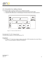
1
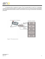
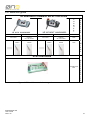
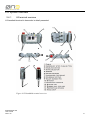
0n3
H3 Series
User Manual
Version 1.00
Copyright © 2013 0n3 S.r.l. – Rome, Italy
Subject to change without notice
The information contained in this document is provided for informational purposes only. While efforts were made to verify the accuracy of the information contained in this documentation, it is provided “as is” without warranty of any kind.
Third-party brands and names are the property of their respective owners.
www.0n3.eu
MANUGENH3 0N3
User manual
VER 1.00
2
Contents
Acronyms
5
General Information
1.1
Manual organization
1.2
Organization of safety notices
1.3
Safety guidelines
1.3.1
Responsibilities
1.3.2
Intended use
1.3.3
Protection against electrostatic discharges
1.3.4
Transport and storage
1.3.5
Installation
1.3.6
Operation main facts
1.3.7
Supply voltage
1.3.8
Emergency Stop push-button
1.3.9
Enabling Device
1.3.10
State Selector
1.3.11
Environmentally-friendly disposal
1.3.11.1
Disposal
6
6
6
6
6
8
8
8
8
9
9
9
10
11
12
12
Technical data
2.1
Introduction
2.2
Selection guide
2.3
Product coding
2.4
System overview
2.4.1
H3 terminal overview
2.4.1.1
Ergonomics
2.4.1.2
Housing
2.4.1.3
Operating and display field
2.4.1.4
Electronics
2.4.1.5
Input devices
2.4.1.5.1
Override potentiometers
2.4.1.5.2
Handwheel (optional)
2.4.1.5.3
Rubber keypad
2.4.1.6
Interfaces to NC/PLC
2.4.1.7
USB interface
2.4.1.8
Touch screen pen
2.4.1.9
Safety related devices
2.4.2
Connection box overview
2.4.3
Dimensions
2.4.3.1
Terminal
2.4.3.2
Connection Box
13
15
16
17
17
17
18
18
18
18
19
19
19
19
20
20
21
21
22
23
23
24
MANUGENH3 0N3
User manual
VER 1.00
3
2.5
Technical data details
2.5.1
Handheld terminal specifications
2.5.1.1
Handheld terminal chemical resistance
2.5.1.1.1
Test results
2.5.2
Cable connections
2.5.3
Cable connector specifications and pin-out
2.5.3.1
DB25 connector pin-out
2.5.4
Safety-related devices
2.5.4.1
Emergency Stop button
2.5.4.2
Enabling device
2.5.4.3
State Selector
2.6
Connection box cabling scheme
2.6.1
Cabling: H3 to Connection Box
2.6.2
Cabling: Connection Box to CN/PLC
2.7
Standards
2.7.1
EC Directives
2.7.2
International Safety Standards
MANUGENH3 0N3
User manual
VER 1.00
25
25
27
28
29
30
30
31
31
31
31
32
33
35
36
36
36
4
Acronyms
CNC:
DC:
DLL:
ESD:
HMI:
ISO:
TFT:
LCD:
MDI:
MTTFd:
OS:
PCB:
PLC:
PUR:
RGB:
R/W:
USB:
VDC:
XML:
PN:
SN:
MANUGENH3 0N3
User manual
VER 1.00
Computer Numerical Control
Diagnostic Coverage
Dynamic-Link Library
Electrostatic Discharge
Human-Machine Interface
International Organization for Standardization
Thin Film Transistor
Liquid Crystal Display
Manual Data Input
Mean Time To dangerous Failure
Operative System
Printed Circuit Board
Programmable Logic Controller
Polyurethane
Red Green Blue
Read/Write
Universal Serial Bus
Volts of Direct Current
eXtensible Markup Language
Part Number
Serial Number
5
chapter 1
General Information
1.1 Manual organization
This user manual is inteded to give all kind of information regarding H3 handheld terminal. Chapter 1
is dedicated to general information, operation and safety main notices and an high level explanation
of the device. Chapter 2 at first gives an overview to each component and then gives the detailed
technical data.
1.2 Organization of safety notices
All safety notices in this manual are specified as follows:
Safety notice
Danger!
Caution!
Warning!
Information:
Description
Respecting guidelines and regulations avoids life-risks
Respecting guidelines and regulations avoids severe injuries or damage to material
Respecting guidelines and regulations avoids injuries or
damage to material
Respecting guidelines and regulations avoids errors
1.3 Safety guidelines
1.3.1
Responsibilities
H3 handheld terminal is a small, light and comfortable remote system controller which, appositely
configured and connected to a machine control logic and safety, guarantees machine control and
configuration and the implementation of safety related functions.
All configuration and control commands selected through the keyboard or the touch screen display,
the optional handwheel and the potentiometers status are sent to the machine control logic through
a serial or ethernet communication channel. H3 is available in two versions, depending on the
desired communication interface: ETHERNET or RS-422.
The safety related devices available on the H3 handheld terminal are: Emergency Stop push-button,
Enabling Device and State Selector.
All handheld terminal outputs: ETHERNET/RS-422 signals and the safety related devices outputs,
are cable connected to the machine control logic.
MANUGENH3 0N3
User manual
VER 1.00
6
Danger!
•
User is responsible for the correct device installation and interfacing to the machine control
logic.
•
User is responsible for implementing the machine safety related functions. H3 handheld
terminal provides the best state of the art technology safety devices.
•
User should implement the safety related functions according to the application safety level
determined in a previous risk analysis.
•
User, during machine control logic implementation, is responsible for considering all conditions
related to the machine operations:
a) checking the Emergency Stop push-button, Enabling Device and State Selector
status;
b) checking all possible further safety devices available on board of the machine: safety
fences, optical barriers and so on.
•
User is responsible for considering all further safety and accident prevention guidelines related
to the particular working environment in addition and independently from this document.
•
User is responsible for observing all safety precautions applying to industrial control systems
in accordance with national and international regulations.
•
User is responsible for observing that all installation, commissioning and maintenance
tasks must be carried out only by qualified personnel, so by persons who are familiar with
transport, mounting, installation, commissioning and operation of the product and who have
the appropriate qualifications. Furthermore it is suggested to follow all national accident
prevention guidelines.
•
All safety guidelines, cabling schemes, mechanical and electrical limit values listed in the
technical data must be read before installation and commissioning and strictly respected.
•
User is not allowed to take care of the mainteinance and repair of the safety devices on board
of 0N3 H3 terminal. Each mainteinance and repair operation must be remanded to 0N3 srl.
Information:
•
All instructions contained in this manual ensuring user safety must be taken in consideration.
Each non-conformity could cause the safety functions integrated in the handheld terminal not
to work properly.
MANUGENH3 0N3
User manual
VER 1.00
7
1.3.2
Intended use
H3 handheld terminal has been designed, developed, and manufactured for conventional use in
industry. It was not designed, developed, and manufactured for any use involving serious risks or
hazards that could lead to death, injury, serious physical damage, or loss of any kind without the
implementation of exceptionally stringent safety precautions. Such risks and hazards include the
use of H3 handheld terminal in the following applications:
•
•
•
•
•
•
1.3.3
nuclear reactions monitoring in nuclear power plants;
flight control systems;
flight safety;
mass transit control systems;
medical life support systems;
control of weapons systems.
Protection against electrostatic discharges
Electrical components that are vulnerable to electrostatic discharge (ESD) must be handled
accordingly.
Danger!
•
•
1.3.4
Do not touch the connector contacts;
Do not touch the contact tips when removing the protection covers.
Transport and storage
All kind of environmental (temperature, aggressive atmospheres, humidity) and mechanical stresses
over the accepted limits explained in 2.5 must be avoided during transport and storage of the devices.
Two main considerations must be done in order to prevent damages during transport:
Warning!
•
•
1.3.5
always use the original packaging;
always keep the right environmental conditions as explained in the technical data.
Installation
Installation must take place according to the documentation and using suitable equipment and tools.
Warning!
•
•
•
All devices must be installed by qualified personnel and without voltage supplied
All national regulations about accident prevention must be taken into account
Electrical installation must follow the fundamental guidelines (line cross section, protective
ground connection, the electrical limits explained in the technical data etc.)
MANUGENH3 0N3
User manual
VER 1.00
8
1.3.6
Operation main facts
Warning!
•
•
•
•
1.3.7
Take care not to squeeze and thus damage the cable with any object.
Make sure that nobody can fall over the cable to avoid that the device falls to grund.
Do not lay the cable over sharp edges to avoid damaging the cable sheat.
Always operate the touch screen with the proper touch-pen. Never use sharp objects that
could damage the touch screen.
Supply voltage
Caution!
•
1.3.8
The supply circuit must be protected using a 0.25A slow-blow fuse.
Emergency Stop push-button
The Emergency Stop push-button provides two redundant switching N.C. (Normally Closed) contacts.
User should directly connect the Emergency Stop push-button outputs to the machine cabinet and
monitoring devices. For further information about the handheld terminal cable pin-out please refer
to paragraph 2.5.2.
For the related safety function once it is interfaced with the machine control logic (please refer to
paragraph 2.5.4.1).
Warning!
•
•
•
•
•
•
User is responsible for interfacing the Emergency Stop push-button to the machine control
logic and implementing the Emergency Stop function according to the safety level determined
in a previous risk analysis.
User is responsible for interfacing the Emergency Stop push-button to the machine control
logic implementing the Emergency stop function in category 0 or category 1.
In case of drop or other possible damages of the device, the stop function operation must
always be checked by the operator.
Releasing the Emergency Stop push-button must never cause an uncontrolled restart. User
is responsible for implementing this controls on the machine control logic.
The Emergency Stop push-button on the handheld terminal is not a substitute for the
Emergency Stop push-button located on the machine.
For further and more detailed information about the Emergency Stop push-button, as the
electrical and mechanical life, please refer to paragraph 2.4.1.9 and 2.5.4.1.
MANUGENH3 0N3
User manual
VER 1.00
9
1.3.9
Enabling Device
The Enabling Device is a three positions enable switch providing two redundant switching N.O.
(Normally Open) contacts.
User should directly connect the Enabling Device outputs to the machine cabinet and monitoring
devices. For further information about the handheld terminal cable pin-out please refer to paragraph
2.5.2.
Two positions, “Null” and “Panic”, represent off condition while only the “Enable” position allows
activation.
For the related safety function once it is interfaced with the machine control logic (please refer to
paragraph 2.5.4.2).
Warning!
•
•
•
•
•
User is responsible for interfacing the Enabling Device to the machine control logic and
implementing the enabling function according to the safety level determined in a previous
risk analysis.
The enable switch fulfils its protective function only if the operator can recognize the danger
in time.
In case of dangerous states the logic controller must provide that, additionally to the enable
switch, another conscious start command should be required to allow activation.
The only person permitted in the dangerous area is the person activating the enable switch.
For further and more detailed information about the enable switch, as the electrical and
mechanical life, please refer to paragraph 2.4.1.9 and 2.5.4.2.
Functionality
The Enabling Device can have three different positions:
Switch position
1
2
3
Function
Zero position
Enable
Panic
Enable switch
Not pressed
Pressed
Pushed all the way in
Switching contact
Off (opened)
On (engaged)
Off (opened)
The positions null and panic must be cabled and controlled by the machine logic in order to guarantee
a stop category 0 or 1.
Zero position
When not pressed the Enabling Device returns to the zero position
Figure 1: Zero position
MANUGENH3 0N3
User manual
VER 1.00
10
Enable position
When pressed the Enabling Device goes into the enabling position. This condition is often associated
to machine movement activation. When released it goes back to the null position.
Figure 2: Enable position
Panic position
When the Enabling Device is pushed all the way in it goes to the panic position which corresponds
to the same contact condition as the zero state.
Figure 3: Panic position
If the switch is pushed all the way in and then released it goes directly to the null state skipping the
enable position.
1.3.10
State Selector
The State Selector is a 16 states BCD coded rotary switch with four non-redundant outputs and a
common contact.
User should directly connect the State selector outputs and common contact to the machine cabinet
and monitoring devices. For further information about the handheld terminal cable pin-out please
refer to paragraph 2.5.2.
For the related safety function once it is interfaced with the machine control logic (please refer to
paragraph 2.5.4.3).
MANUGENH3 0N3
User manual
VER 1.00
11
Warning!
•
•
•
User is responsible for interfacing the State selector to the machine control logic and
implementing the state selecting function according to the safety level determined in a
previous risk analysis.
The State Selector function should be only related to the selection of the various working
modes available on the machine by the logic controller.
For further and more detailed information about the State Selector, as the electrical life,
plaese refer to paragrah 2.4.1.9 and 2.5.4.3.
1.3.11
Environmentally-friendly disposal
All components related to H3 handheld terminal are designed to respect the environment and reduce
as much as possible its impact on pollution.
1.3.11.1
Disposal
It is important to specify how to dismiss the different components of H3 terminal in order to have an
environmentally-friendly recycling process.
Component
Cable
Electronic boards
Paper packaging
Plastic packaging
MANUGENH3 0N3
User manual
VER 1.00
Disposal
Electronic recycling
Paper recycling
Plastic recycling
12
Chapter 2
Technical data
2.1 Introduction
H3 handheld terminal is a small, light and robust mobile panel featuring a powerful processor
widely used in industrial products, a high reliability solid state disc and a RAM memory bigger and
faster than H2, a comfortable 5” TFT LCD color touch display and a USB 2.0 port. The processor
runs Windows CE 6.0 operating system. Customer has complete freedom of operation on the OS
and can build his own application, use third party software or run the available application from
0N3. Emergency Stop push-button, Enabling Device and State Selector are available on board. All
configuration and control commands selected through the keyboard or the touch screen display, the
optional Handwheel and the potentiometers status are sent to the machine control logic through an
ETHERNET or RS-422 serial communication channel. The data signals (RS-422 /ETHERNET), the
Emergency Stop push-button, Enabling Device and State Selector outputs are cable connected to
the machine control logic.
Figure 4: H3 handeld terminal
MANUGENH3 0N3
User manual
VER 1.00
13
A Connection Box complete the system. The Connection Box is useful for a comfortable
connection to the machine cabinet. For further info please refer to 2.6. All of the components related to
the H3 handheld terminal and the interface to the machine control logic are hereunder schematically
presented:
Figure 5: H3 system overview
MANUGENH3 0N3
User manual
VER 1.00
14
2.2 Selection guide
H3 HANDHELD TERMINAL SELECTION GUIDE
H
A
N
D
W
H
E
E
L
RS-422
ETHERNET
RS-422
ETHERNET
INTERFACE
BLACK CABLE
10m or 20m
BLUE CABLE
(CAT5 E)
5m, 10m or 20m
BLACK CABLE
10m or 20m
BLUE CABLE
(CAT5 E)
5m, 10m or 20m
CABLE
TYPE
FREE
WIRES
CONNECTION
TYPE
DB-25
FREE
WIRES
FREE
WIRES
DB-25
FREE
WIRES
H
A
N
D
H
E
L
D
T
E
R
M
I
N
A
L
H3 ACCESSORIES
CONNECTION
BOX
A
C
C
E
S
S
O
R
I
E
S
Figure 6: H3 handeld terminal selection guide
MANUGENH3 0N3
User manual
VER 1.00
15
2.3 Product coding
Product coding scheme as below. For ordering please contact your sales representative.
Figure 7: Product coding scheme
MANUGENH3 0N3
User manual
VER 1.00
16
2.4 System overview
2.4.1
H3 terminal overview
H3 handheld terminal is hereunder in detail presented:
Figure 8: H3 handheld terminal overview
MANUGENH3 0N3
User manual
VER 1.00
17
2.4.1.1
•
•
•
•
•
Functional hand grip, user configurable;
Comfortable and safe access to safety related devices;
Comfortable and secure handling using rubber membrane keyboard and covering surface;
Comfortable handling, also using gloves, thanks to well-designed command key spacing;
Clear display, user configurable brightness.
2.4.1.2
•
•
•
Ergonomics
Housing
Vibration and shock resistant.
Non-flammable material housing (fulfils UL 94-HB), impact-resistant, water-resistant IP
64, cleaning agents (alcohol and fabric conditioner), oils, cutting oils (drilling oils), fat and
lubricants resistant.
Extremely robust housing.
2.4.1.3
Operating and display field
Rubber covered keys with mechanical pressure point.
2 LED’s:
- RED color: indicates hardware failures;
- GREEN color: may be fixed or blinking and is controlled by OS;
• Touch screen TFT LCD Display.
•
•
2.4.1.4
•
CPU
•
•
•
•
•
•
Electronics
600MHz ARM Cortex-A8 core;
16kB instruction Cache;
256kB L2 Cache;
Embedded Graphic engine;
Flash Memory: 128MB Flash NOR Solid State Disc (SSD);
RAM Memory: 128MB DDR2 SDRAM.
MANUGENH3 0N3
User manual
VER 1.00
18
2.4.1.5
Input devices
2.4.1.5.1
Override potentiometers
The two over-ride potentiometers can be used for different purposes, for instance setting the spindle
speed or the machine movement speed along a certain axis.
•
Resolution: 0-255 linear
2.4.1.5.2
Handwheel (optional)
The handwheel is an optional accessory. It can be used for the machine movement fine tuning in the
“handwheel incremental JOG” working mode.
The handwheel counts 40 detents per each 360◦ turn. Clockwise turns decrement while counterclockwise turns increment the counter.
2.4.1.5.3
Rubber keypad
The mobile panel has a rubber keypad containing 19 keys. 6 keys are command keys, useful for a
direct machine control. The remaining 13 keys are function keys, useful for navigating and operating
through the panels of the software application. The letter or the symbol printed on the keys reminds
the function.
Figure 9: Keypad
MANUGENH3 0N3
User manual
VER 1.00
19
2.4.1.6
Interfaces to NC/PLC
H3 is available in two versions according to the desired communication interface:
• RS-422: Full-duplx seil interface; bitrate is user configurable.
• ETHERNET: 100 Mbps Fast Ethernet
• fulfils standards: IEEE 802.3, IEEE 802.3u 100BASE-TX
• supports auto cross-over (AUTO-MDI) function.
2.4.1.7
•
•
•
USB interface
USB 2.0 HOST interface
USB type-A connector
max 500mA output current
MANUGENH3 0N3
User manual
VER 1.00
20
2.4.1.8
Touch screen pen
The touch screen pen is easily accessible in the back, on the right side of the terminal.
Figure 10: Touch screen pen
2.4.1.9
Safety related devices
Hereunder is shown the detail for the safety related devices position:
Figure 11: Safety related devices position
For all the information about the safety related devices and functions please refer to paragraphs
1.3.8, 1.3.9, 1.3.10 and 2.5.4.
MANUGENH3 0N3
User manual
VER 1.00
21
2.4.2
Connection box overview
Connection Box is an easy to install DIN rail module which eases H3 installation and connection
inside the machine rack.
Connection Box is a splitter which, once connected to H3 output connector or output wires, splits
all signals on screw terminals or RJ45 connector (ETHERNET signals only) easing all cabling
operations.
Figure 13: Connection board
MANUGENH3 0N3
User manual
VER 1.00
22
2.4.3
2.4.3.1
Dimensions
Terminal
Figure 12: Terminal (dimensions in millimeters)
MANUGENH3 0N3
User manual
VER 1.00
23
2.4.3.2
Connection Box
Figure 13: Connection Box dimensions
MANUGENH3 0N3
User manual
VER 1.00
24
2.5 Technical data details
2.5.1 Handheld terminal specifications
Operating System
CPU
Flash Memory
RAM Memory
RS-422 Interface
(H3 RS-422 version only)
ETHERNET Interface
(H3 ETHERNET version only)
USB interface
Output current
Connector
Keyboard
Command keys
Softkeys
Status LED
Display
Diagonal
Colors
Resolution
Contrast ratio
Viewing angle:
• Horizontal
• Vertical
Background lighting:
• Brightness
• Half-brightness time
Touch screen technology
MANUGENH3 0N3
User manual
VER 1.00
FEATURES
Windows CE 6.0
600 MHz ARM Cortex-A8 core
16kB instruction Cache
256kB L2 Cache
Embedded Graphic engine
128MB Flash NOR Solid State Disc (SSD)
128MB DDR2 SDRAM
Full duplex serial communication
Bitrate: user configurable
Connection: 2 shielded twisted pairs
10/100Mbps Fast Ethernet
Fulfils standards: IEEE 802.3, IEEE 802.3u
100BASE-TX
Supports auto cross-over function (AUTO-MDI)
Connection: 2 shielded twisted pairs
USB 2.0 HOST
max 500mA
USB type-A
Rubber keypad
6
13
Bicolor LED: RED/GREEN
TFT LCD
5” (12,7cm)
16 milions
RGB 480x272 pixels
500:1
Direction Right / Direction Left = 70°
Direction Up = 50° / Direction Down = 70°
300cd/m2
at least 20000 hours
Resistive sensor technology
25
Power Supply
Rated Voltage
Max interruption of the supply
Starting current
Power consumption
Electrical insulation
Emergency Stop Button
Enabling Device
State Selector
Handwheel (optional)
Override potentiometer
Handheld terminal color
Outer dimensions
Length
Height
Width
Weight (without cable)
Temperature
Operating temperature
Trasport and storage temperature
Relative humidity
Operating
Transport
Operating Altitude
Protection Degree
Flame resistance
MANUGENH3 0N3
User manual
VER 1.00
24VDC ± 25%
10ms
250mA @ 24V
3.12W (typ) = 130mA @ 24V
No
2 N.C. contacts
3 positions switches, 2 N.O. contacts
16 state BCD coded
40 detents per turn
2 linear potentiometers
MECHANICS
Body structure: RAL 7035; Rubber part:
RAL7016
220mm
50mm
130mm
700g (H3 without handwheel)
710h (H3 with hadwheel)
ENVIRONMENT
+5° to +45°C
-20° to +70°C
Max 95%: non-condensing
Max 95%: non-condensing
Max 3000m
IP64
Handheld terminal housing fulfils UL 94-HB
26
2.5.1.1
Handheld terminal chemical resistance
Test 1 (Less strict)
The units under test (UUT) are placed in a closable plastic box (120 x 85 x 65 mm).
A ball of absorbent cotton appositely tinctured with solvent will be placed above the UUT; to avoid
early evaporation, a generic solid body will be put over the ball or, in a more simply way, the closable
plastic box will be closed.
After a 10 minutes wait, the eventual body and the ball of absorbent cotton will be removed; the
solvent that remains on the UUT will not be wiped off and the box will be closed immediately
afterwards for 24 hours.
The test will be performed at environmental temperature (about 20 ◦C).
Test 2 (Very strict)
The units under test (UUT) are fully and thoroughly wet by solvent, then will be closed into a closable
box (120 x 85 x 65 mm) for 24 h.
Approximately 5 ml solvent will be sprayed over the UUT. The box will be closed and the UUT will
remain in the closed box for at least 24 hours.
The test will be performed at environmental temperature (about 20 ◦C).
Touchscreen test procedure
The Touchscreen is placed into a closable plastic box (120 x 85 x 65 mm) and a ball of absorbent
cotton appositely tinctured with solvent will be placed above it, then the box will be closed for 1 h.
The test will be performed at environmental temperature (about 20 ◦C).
MANUGENH3 0N3
User manual
VER 1.00
27
2.5.1.1.1 Test results
Chemical Solvent
Test 1 passed
Test 2 passed
Denathured
Ethyl
Alcohol
Rubber (Keyboard)
Handels
Terminal housing
Rubber cup
Rubber (lateral cover)
Rubber (Keyboard)
Handles
Terminal housing
Rubber cup
Rubber (lateral cover)
Diesel
Rubber (Keyboard)
Handels
Terminal housing
Rubber cup
Rubber (lateral cover)
Handles
Terminal housing
Rubber cup
Rubber (lateral cover)
Unleaded Gasoline
Blu Diesel
Silicone Spray
Rubber (Keyboard)
Handels
Terminal housing
Rubber cup
Rubber (lateral cover)
Rubber (Keyboard)
Handels
Terminal housing
Rubber cup
Rubber (lateral cover)
Rubber (Keyboard)
Handles
Notes
Test 2:
Rubber (Keyboard):
heavy deformation;
reduced hardness
Test 2:
Terminal housing:
housing gets doughy
Rubber cup
Rubber (lateral cover)
Handles
Terminal housing
Rubber cup
Rubber (lateral cover)
Test 2:
Rubber (Keyboards):
rubber gets doughy
Rubber (Keyboard)
Handels
Terminal housing
Rubber cup
Rubber (lateral cover)
Rubber (Keyboard)
Test 2:
Handles: loss of color
Kluber CONSTANT OY 32
Rubber (Keyboard)
Handels
Terminal housing
Rubber cup
Rubber (lateral cover)
Rubber (Keyboard)
Handles
Terminal housing
Rubber cup
Rubber (lateral cover)
Acetone
Rubber (Keyboard) Rubber Rubber (Keyboard) Rubber Test 1 and 2:
(lateral cover)
(lateral cover)
Handles: loss of color
Terminal housing: clouding
Rubber cup: swelling
Shell Garin 9603 M15
Rubber (Keyboard)
Handels
Terminal housing
Rubber cup
Rubber (lateral cover)
Terminal housing
Rubber cup
Rubber (lateral cover)
Rubber (Keyboard)
Handles
Terminal housing
Rubber cup
Rubber (lateral cover)
Touchscreen test results
Test passed with the following solvents:
•
•
•
•
•
Unleaded Gasoline;
Denatured Ethyl Alcohol;
Diesel
Kluber CONSTANT OY 32;
Acetone.
MANUGENH3 0N3
User manual
VER 1.00
28
2.5.2
Cable connections
Ethernet version
Ethernet Tx+ (Shielded Twisted Pair)
Ethernet Tx- (Shielded Twisted Pair)
Ethernet Rx- (Shielded Twisted Pair)
Ethernet Rx+ (Shielded Twisted Pair)
State Selector Common
State Selector Bit 0
State Selector Bit 1
State Selector Bit 2
State Selector Bit 3
Enabling Device N.O. Contact 1
Enabling Device N.O. Contact 1
Enabling Device N.O. Contact 2
Enabling Device N.O. Contact 2
Power Supply GND
Power Supply 24V
Stop Button N.C. Contact 1
Stop Button N.C. Contact 1
Stop Button N.C. Contact 2
Stop Button N.C. Contact 2
White/Green
Green
Orange
White/Orange
Red/Blu
Grey/Pink
Yellow/White
White/Green
Brown/Green
Yellow
Green
White
Brown
Blue
Red
Black
Pink
Purple
Grey
RS-422 Serial Version
Serial RS-422 Tx+ (Shielded Twisted Pair)
Serial RS-422 Tx- (Shielded Twisted Pair)
Serial RS-422 Rx- (Shielded Twisted Pair)
Serial RS-422 Rx+ (Shielded Twisted Pair)
State Selector Common
State Selector Bit 0
State Selector Bit 1
State Selector Bit 2
State Selector Bit 3
Enabling Device N.O. Contact 1
Enabling Device N.O. Contact 1
Enabling Device N.O. Contact 2
Enabling Device N.O. Contact 2
Power Supply GND
Power Supply 24V
Stop Button N.C. Contact 1
Stop Button N.C. Contact 1
Stop Button N.C. Contact 2
Stop Button N.C. Contact 2
MANUGENH3 0N3
User manual
VER 1.00
Yellow
Green
Pink
Grey
Yellow/Brown
Yellow/White
Grey/Brown
White/Green
Brown/Green
White/Orange
Grey/White
Red/Blu
Blu
Brown
White
Black
Grey/Pink
Purple
Red
29
2.5.3
Cable connector specifications and pin-out
H3 handheld terminal cable will terminate optionally with a DB25 male connector, with a circular
male plug or with no connector.
Both the DB25 connector and the circular plug provide a metal backshell internally connected to the
cable external and internal shieldings and to the handheld terminal Ground. This will let H3 terminal
ground and shieldings to be connected with the machine cabinet “earth”.
Figure 14: DB25 male connector (dimensions in millimeters)
2.5.3.1
DB25 connector pin-out
Signal
MANUGENH3 0N3
User manual
VER 1.00
Pin
Not connected
1
Not connected
2
RS-422/Ethernet TX+
3
RS-422/Ethernet TX-
4
RS-422/Ethernet RX-
5
RS-422/Ethernet RX+
6
State Selector (common)
7
State Selector (bit 0)
8
State Selector (bit 1)
9
State Selector (bit 2)
10
State Selector (bit 3)
11
Enabling Device C1 contact (normally open)
12
Enabling Device C1o contact (normally open)
13
Enabling Device C2 contact (normally open)
14
Enabling Device C2o contact (normally open)
15
Not connected
16
Shield (Ground)
17
Not connected
18
Power Supply 0V dc (GND)
19
Power Supply +24V dc
20
Not connected
21
Emergency Stop Button C1a (normally closed)
22
Emergency Stop Button C1b (normally closed)
23
Emergency Stop Button C2a (normally closed)
24
Emergency Stop Button C2b (normally closed)
25
30
2.5.4
2.5.4.1
Safety-related devices
Emergency Stop button
Characteristics
Switchable nominal voltage
Switchable nominal current
Reliability:
• Mechanical life
• Electrical life
• Maximum operating frequency
2.5.4.2
Reliability:
• Mechanical life
Electrical life
Maximum operating frequency
2.5.4.3
24VDC ± 25%
2A (DC-12 resistive load)
1A (DC-13 inductive load)
250000 operations minimum
250000 operations minimum
900 operations/hour
Enabling device
Characteristics
Switchable nominal voltage
Switchable nominal current
•
•
Value
Value
24VDC ± 25%
1A (DC-12 resistive load)
0.7A (DC-13 inductive load)
Position 1→2: 1000000 operations minimum
Position 1→2→3→1: 100000 operations minimum
100000 operations minimum
1200 operations/hour
State Selector
Characteristics
Switchable nominal voltage
Continuous (Non-switching) current
capacity
Reliability:
• Electrical life
MANUGENH3 0N3
User manual
VER 1.00
Value
24VDC ± 25%
200mA
25000 operations minimum
31
2.6 Connection box cabling scheme
The Connection Box, as shown in picture 18, is divided in two parts:
• Terminal Side (upper part): for interfacing H3 terminal to the Connection Box;
• Controller Side (lower part): for interfacing the Connection Box to the machine NC/PLC.
Figure 15: Connection Box TOP view
Connectors J6, J7, J10, J11 are not used.
Connection Box features a 0.25A slow-blow fuse (F1).
Caution!
•
In case of F1 fuse break, please replace only with a 0.25A slow-blow fuse (size 20mm x
5mm). Fuse type example: Littlefuse 0218.250HXP.
MANUGENH3 0N3
User manual
VER 1.00
32
2.6.1
Cabling: H3 to Connection Box
Open connection
User must connect cable wires to the terminal J1. For a correct cabling please refer to the following
table:
VERSION
Wire Connection
Yellow
Green
Pink
Grey
Yellow/Brown
Yellow/White
Grey/Brown
White/Green
Brown/Green
White/Orange
Grey/White
Red/Blu
Blu
Brown
White
Black
Grey/Pink
Purple
Red
MANUGENH3 0N3
User manual
VER 1.00
RS-422
Connection Box J1
3
4
5
6
7
8
9
10
11
12
13
14
15
19
20
22
23
24
25
33
VERSION
Wire Connection
White/Green
Green
Orange
White/Orange
Red/Blu
Grey/Pink
Yellow/White
White/Green
Brown/Green
Yellow
Green
White
Brown
Blue
Red
Black
Pink
Purple
Grey
MANUGENH3 0N3
User manual
VER 1.00
ETHERNET
Connection Box J1
3
4
5
6
7
8
9
10
11
12
13
14
15
19
20
22
23
24
25
34
Both external and internal cable shieldings (copper braids) should be connected to J4 ”Shield” pin.
DB-25 termination
User must connect H3 DB-25 male connector to J14 female connector.
2.6.2
Cabling: Connection Box to CN/PLC
For a correct cabling please refer to the following table:
Connection Box ouput con- Signal meaning
tact Enabling Device
Terminal J8 - C1
Contact C1
Terminal J8 - C1o
Terminal J8 - C2
Contact C2
Terminal J8 - C2o
Emergency Stop Push-button
Terminal J9 - C1a
Contact C1
Terminal J9 - C1b
Terminal J9 - C2a
Contact C2
Terminal J9 - C2b
State Selector
Terminal J4 - COM
Common Contact
Terminal J4 - 0
Bit 0
Terminal J4 - 1
Bit 1
Terminal J4 - 2
Bit 2
Terminal J4 - 3
Bit 3
RS-422 Interface (H3 RS-422 version only)
Terminal J5 - TX+
Serial Port TX +
Terminal J5 - TXSerial Port TX Terminal J5 - RX+
Serial Port RX +
Terminal J5 - RXSerial Port RX Terminal J5 - GND
Serial Port GND
ETHERNET interface (H3 ETHERNET version only)
RJ45 connector J12
Ethernet Port
Power Supply
Terminal J13 - 24V
Power Supply 24V
Terminal J13 - GND
Power Supply GND
Terminal J13 - Earth
Machine Earth Ground
MANUGENH3 0N3
User manual
VER 1.00
Note
N.O. Contact
N.O. Contact
N.C. Contact
N.C. Contact
35
2.7 Standards
H3 handheld terminal has been designed in order to conform to the following european directives
and international standards:
2.7.1
EC Directives
Directive
2004/108/EC
2.7.2
Description
Electromagnetic Compatibility Directive (EMC)
International Safety Standards
Standard
EMC
EN 61000-6-2
EN 61000-6-4
Description
Electromagnetic Compatibility (EMC) Part 6-2: Generic Standards - Immunity for Industrial Environments
Electromagnetic Compatibility (EMC) Part 6-4: Generic Standards - Emission for Industrial Environments
Degrees of protection and environmental tests
EN 60529 + A1
Degrees of protection provided by enclosures (IP
code)
Emergency Stop Push-button conforming to:
IEC 60947-5-5, 6.2
Safety Lock Mechanism
IEC 60947-5-5, 5.2
IEC 60947-5-1, Annex Direct opening action mechanism
K
EN ISO13850, 4.2, 4.3, 4.4
Enabling Device conforming to:
IEC 60947-5-1
EN 60947-5-1
JIS C8201-5-1
UL508
CSA C22.2 No 14
IEC 60947-5-8
Low-voltage switchgear and controlgear
MANUGENH3 0N3
User manual
VER 1.00
36