1
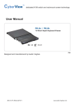
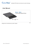
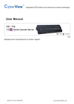
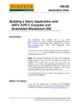
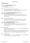
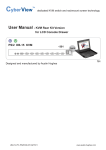
Inspired by Your Data Center
User Manual - Automatic Transfer Switch
230V
Amp : 10A / 16A
Outlet : C13 / C19
208V
Amp : 20A
Outlet : C13 / C19
110V
Amp : 15A / 20A
Outlet : US NEMA
Designed and manufactured by Austin Hughes
UM-IP-ATS-Q215V2
www.austin-hughes.com
Legal Information
First English printing, October 2002
Information in this document has been carefully checked for accuracy; however, no guarantee is given to the correctness
of the contents. The information in this document is subject to change without notice. We are not liable for any injury or
loss that results from the use of this equipment.
Safety Instructions
Please read all of these instructions carefully before you use the device. Save this manual for
future reference.
■
■
■
■
■
■
■
■
■
■
■
Unplug equipment before cleaning. Don’t use liquid or spray detergent; use a moist cloth.
Keep equipment away from excessive humidity and heat. Preferably, keep it in an air-conditioned environment with
temperatures not exceeding 40º Celsius (104º Fahrenheit).
When installing, place the equipment on a sturdy, level surface to prevent it from accidentally falling and causing dam
age to other equipment or injury to persons nearby.
When the equipment is in an open position, do not cover, block or in any way obstruct the gap between it and the
power supply. Proper air convection is necessary to keep it from overheating.
Arrange the equipment’s power cord in such a way that others won’t trip or fall over it.
If you are using a power cord that didn’t ship with the equipment, ensure that it is rated for the voltage and current
labelled on the equipment’s electrical ratings label. The voltage rating on the cord should be higher than the one listed
on the equipment’s ratings label.
Observe all precautions and warnings attached to the equipment.
If you don’t intend on using the equipment for a long time, disconnect it from the power outlet to prevent being dam
aged by transient over-voltage.
Keep all liquids away from the equipment to minimize the risk of accidental spillage. Liquid spilled on to the power
supply or on other hardware may cause damage, fire or electrical shock.
Only qualified service personnel should open the chassis. Opening it yourself could damage the equipment and invali
date its warranty.
If any part of the equipment becomes damaged or stops functioning, have it checked by qualified service personnel.
What the warranty does not cover
■
■
■
Any product, on which the serial number has been defaced, modified or removed.
Damage, deterioration or malfunction resulting from:
Accident, misuse, neglect, fire, water, lightning, or other acts of nature, unauthorized product modification, or
failure to follow instructions supplied with the product.
Repair or attempted repair by anyone not authorized by us.
Any damage of the product due to shipment.
Removal or installation of the product.
Causes external to the product, such as electric power fluctuation or failure.
Use of supplies or parts not meeting our specifications.
Normal wear and tear.
Any other causes which does not relate to a product defect.
Removal, installation, and set-up service charges.
□
□
□
□
□
□
□
□
Regulatory Notices Federal Communications Commission (FCC)
This equipment has been tested and found to comply with the limits for a Class B digital device, pursuant to Part 15 of the
FCC rules. These limits are designed to provide reasonable protection against harmful interference in a residential installation.
Any changes or modifications made to this equipment may void the user’s authority to operate this equipment. This
equipment generates, uses, and can radiate radio frequency energy and, if not installed and used in accordance with the
instructions, may cause harmful interference to radio communications.
However, there is no guarantee that interference will not occur in a particular installation. If this equipment does cause
harmful interference to radio or television reception, which can be determined by turning the equipment off and on, the
user is encouraged to try to correct the interference by one or more of the following measures:
■ Re-position or relocate the receiving antenna.
■ Increase the separation between the equipment and receiver.
■ Connect the equipment into an outlet on a circuit different from that to which the receiver is connected.
UM-IP-ATS-Q215V2
www.austin-hughes.com
Content
Part I. ATS Installation & Connection
Page
< 1.1 > Package Content
1
< 1.2 > Product Overview
2
< 1.3 > Installation
3
< 1.4 > Power Sources Connection
4
< 1.5 > Devices Connection
4
Part II. Model & Specification
< 2.1 > 230V ATS
5
< 2.2 > 208V ATS
7
< 2.3 > 110V ATS
9
Unpacking
The equipment comes with the standard parts shown in package content. Check and make sure they are
included and in good condition. If anything is missing, or damaged, contact the supplier immediately.
Part I. ATS Installation & Connection
< 1.1 > Package Content
■ Rackmount ATS unit x 1
■ Mounting Bracket ( set of 3 ) x 1
■ M3.2*4.5 mm screw x 12
UM-IP-ATS-Q215V1
P.1
www.austin-hughes.com
< 1.2 > Product Overview
InfraPower Rackmount Auomatic Transfer Switch ( ATS ) with dual power input provides reliable and
redundant power for single-corded equipment. By the input preference switch, users can define the
preferred power source. If the primary source is unavailable, the ATS will seamlessly source power
from the secondary source without power interruption and downtime. The entire ATS series are designed with a local current meter to easily observe power status and device load.
1
2
3
< Input Preference >
Current ( A )
Primary
Secondary
4
Automatic
Transfer Switch
5
Power
6
8
7
Secondary
Input
Primary
Input
9
1
Local Current Meter
2
Input Preference Switch
3
Circuit Breaker
4
Power LED - primary input
5
Power LED - secondary input
6
Power LED - outlets
7
Primary Input attached with 3M cord & inlet plug
8
Secondary Input attached with 3M cord & inlet plug
9
Outlets
UM-IP-ATS-Q215V1
P.2
www.austin-hughes.com
< 1.3 > Installation
Before Installation
■
■
It is very important to mount the equipment in a suitable cabinet or on a stable surface.
Make sure the place has a good ventilation, is out of direct sunlight, away from sources of excessive
dust, dirt, heat, water, moisture and vibration.
All electrical power and power control wiring must be installed by a qualified electrician
and comply with local and national regulations.
Don’t exceed the outlet, branch or phase limitations
Step 1
1
Use the provided screws to attach the mounting bracket set
( set of 3 ).
Step 2
2
Use the M6 screw set to secure the ATS to your rack
( M6 screws not provided ).
M6
screw
Step 3
3
Use the cable ties to fasten each power cord to the
cord retention tray ( cable ties not provided ).
Cable
tie
UM-IP-ATS-Q215V1
P.3
www.austin-hughes.com
< 1.4 > Power Sources Connection
Step 1 : Before Power Source Connection
This Transfer Switch requires that the applied AC waveforms from
both power sources be in phase with respect to each other. Failure to
do so can potentially damage the unit and create an unexpected
HIGH VOLTAGE
to be present on the pins of either the Primary Source or Secondary
Source plug when disconnected, or on the Primary Source or Secondary Source output receptacles.
All electrical power and power control wiring
must be installed by a qualified electrician and
comply with local and national regulations.
Don’t exceed the outlet, branch or phase
limitations
For questions concerning this requirement please contact
Austin Hughes Technical Support.
E-mail : [email protected]
Step 2 : Power Source Connection
Plug the male end of the power cord into the AC power source.
Power Source Association
After the power source connection, the ATS input power LEDs ( primary & secondary input ) will indicate the
power ON / OFF status. Then slide the input preference switch to the primary input.
Primary
Input / LED
Secondary
Input / LED
Output
Power Source
ON
ON
Primary
OFF
ON
Secondary
ON
OFF
Primary
OFF
OFF
OFF
< 1.5 > Devices Connection
Step 1 : Before connect the devices to the ATS outlet, please keep the device's on / off
switch in the off position.
Step 2 : After connect the devices to the ATS outlet, please power on the device.
Step 3 : Fasten device's power cord to the cord retention tray with cable ties.
Do not exceed the ATS maximum current loads.
UM-IP-ATS-Q215V1
P.4
www.austin-hughes.com
Part II. Model & Specification
< 2.1 > 230V ATS Models
Model List - 10 Amp
Height
Outlet
ATS-H8C13-10A_C14
1U
C13 x 8
ATS-H10C13-10A_C14
1U
C13 x 10
ATS-H12C13-10A_C14
2U
C13 x 12
ATS-H16C13-10A_C14
2U
C13 x 16
Height
Outlet
Model List - 16 Amp
1U
C13 x 8
ATS-H10C13-16A_EN
1U
C13 x 10
ATS-H12C13-16A_EN
2U
C13 x 12
ATS-H16C13-16A_EN
2U
C13 x 16
ATS-H20C13-16A_EN
2U
C13 x 20
ATS-H8C13 / 1C19-16A_EN
1U
C13 x 8 + C19 x 1
ATS-H16C13 / 2C19-16A_EN
2U
C13 x 16 + C19 x 2
Height
Outlet
Inlet x 2
EN16 60309
input plug
Inlet x 2
( 3M cord attached )
ATS-H8C13-16A_C20
1U
C13 x 8
ATS-H10C13-16A_C20
1U
C13 x 10
ATS-H12C13-16A_C20
2U
C13 x 12
ATS-H16C13-16A_C20
2U
C13 x 16
ATS-H20C13-16A_C20
2U
C13 x 20
ATS-H8C13 / 1C19-16A_C20
1U
C13 x 8 + C19 x 1
ATS-H16C13 / 2C19-16A_C20
2U
C13 x 16 + C19 x 2
UM-IP-ATS-Q215V1
C14
input plug
( 3M cord attached )
ATS-H8C13-16A_EN
Model List - 16 Amp
Inlet x 2
( 3M cord attached )
P.5
C20
input plug
www.austin-hughes.com
< 2.1 > 230V ATS Specification
Nominal input voltage
Electrical
230V
Acceptable input voltage
±10% nominal
Input frequency
50 / 60Hz
Inlet plug & cord
2 x C14 / C20 / EN16 60309 plug with 3-meter cord
Outlet connectors
Multiple C13 / C19 outlets
Local meter
3-digital LED current meter
Overload protection
1 x 10-amp circuit breaker for C14 inlet
1 x 16-amp circuit breaker for C20 / EN16 60309 inlet
Transfer time
Physical
25ms maximum
Electrical endurance
1 x 10⁵ operations
Power consumption
Approx. 8VA
Product dimensions ( 1U )
442 x 270 x 43.5 mm ( W x D x H )
Packing dimensions ( 1U )
530 x 380 x 80 mm
Net weight
4.6 kg / 10.1 lb
Gross weight
5.1 kg / 11.2 lb
Product dimensions ( 2U )
442 x 270 x 87.5 mm ( W x D x H )
Packing dimensions ( 2U )
530 x 380 x 140 mm ( W x D x H )
Net weight
Environmental
6.5 kg / 14.3 lb
Gross weight
7 kg / 15.4 lb
Chassis color / materials
Dark / Steel
Operating temperature
-5 to 45°C degree ( 23 to 113°F )
Storage temperature
-25 to 65°C degree ( 13 to 149°F )
Operating humidity
0~95%, non-condensing
Storage humidity
0~95%, non-condensing
EMC
Compliance
FCC & CE certified
Safety
LVD certified
Environment
UM-IP-ATS-Q215V1
(WxDxH)
RoHS2 & REACH compliant
P.6
www.austin-hughes.com
< 2.2 > 208V ATS Models
Model List - 20 Amp
Height
Outlet
ATS-H8C13-20A_L6-20P
1U
C13 x 8
ATS-H10C13-20A_L6-20P
1U
C13 x 10
ATS-H12C13-20A_L6-20P
2U
C13 x 12
ATS-H16C13-20A_L6-20P
2U
C13 x 16
ATS-H20C13-20A_L6-20P
2U
C13 x 20
ATS-H8C13 / 1C19-20A_L6-20P
1U
C13 x 8 + C19 x 1
ATS-H16C13 / 2C19-20A_L6-20P
2U
C13 x 16 + C19 x 2
UM-IP-ATS-Q215V1
Inlet x 2
( 3M cord attached )
P.7
L6-20P
input plug
www.austin-hughes.com
< 2.2 > 208V ATS Specification
Nominal input voltage
Electrical
208V
Acceptable input voltage
±10% nominal
Input frequency
50 / 60Hz
Inlet plug & cord
2 x L6-20P plug with 3-meter cord
Outlet connectors
Multiple C13 / C19 outlets
Local meter
3-digital LED current meter
Overload protection
1 x 20-amp circuit breaker
Transfer time
Physical
25ms maximum
Electrical endurance
1 x 10⁵ operations
Power consumption
Approx. 8VA
Product dimensions ( 1U )
442 x 270 x 43.5 mm ( W x D x H )
Packing dimensions ( 1U )
530 x 380 x 80 mm
Net weight
4.6 kg / 10.1 lb
Gross weight
5.1 kg / 11.2 lb
Product dimensions ( 2U )
442 x 270 x 87.5 mm ( W x D x H )
Packing dimensions ( 2U )
530 x 380 x 140 mm ( W x D x H )
Net weight
Environmental
6.5 kg / 14.3 lb
Gross weight
7 kg / 15.4 lb
Chassis color / materials
Dark / Steel
Operating temperature
-5 to 45°C degree ( 23 to 113°F )
Storage temperature
-25 to 65°C degree ( 13 to 149°F )
Operating humidity
0~95%, non-condensing
Storage humidity
0~95%, non-condensing
EMC
Compliance
FCC & CE certified
Safety
LVD certified
Environment
UM-IP-ATS-Q215V1
(WxDxH)
RoHS2 & REACH compliant
P.8
www.austin-hughes.com
< 2.3 > 110V ATS Models
Model List - 15 Amp
Height
Outlet
ATS-H8US-15A_5-15P
1U
NEMA x 8
ATS-H10US-15A_5-15P
1U
NEMA x 10
ATS-H12US-15A_5-15P
2U
NEMA x 12
ATS-H16US-15A_5-15P
2U
NEMA x 16
ATS-H20US-15A_5-15P
2U
NEMA x 20
Height
Outlet
Model List - 20 Amp
NEMA 5-15P
input plug
Inlet x 2
( 3M cord attached )
ATS-H8US-20A_L5-20P
1U
NEMA x 8
ATS-H10US-20A_L5-20P
1U
NEMA x 10
ATS-H12US-20A_L5-20P
2U
NEMA x 12
ATS-H16US-20A_L5-20P
2U
NEMA x 16
ATS-H20US-20A_L5-20P
2U
NEMA x 20
UM-IP-ATS-Q215V2
Inlet x 2
( 3M cord attached )
P.9
NEMA L5-20P
input plug
www.austin-hughes.com
< 2.3 > 110V ATS Specification
Nominal input voltage
Electrical
110V
Acceptable input voltage
±10% nominal
Input frequency
50 / 60Hz
Inlet plug & cord
2 x NEMA 5-15P / L5-20P plug with 3-meter cord
Outlet connectors
Multiple NEMA 5-20R outlets
Local meter
Overload protection
3-digital LED current meter
1 x 15-amp circuit breaker for NEMA 5-15P inlet
1 x 20-amp circuit breaker for NEMA L5-20P inlet
Transfer time
Physical
25ms maximum
Electrical endurance
1 x 10⁵ operations
Power consumption
Approx. 8VA
Product dimensions ( 1U )
442 x 270 x 43.5 mm ( W x D x H )
Packing dimensions ( 1U )
530 x 380 x 80 mm
Net weight
4.6 kg / 10.1 lb
Gross weight
5.1 kg / 11.2 lb
Product dimensions ( 2U )
442 x 270 x 87.5 mm ( W x D x H )
Packing dimensions ( 2U )
530 x 380 x 140 mm ( W x D x H )
Net weight
Environmental
6.5 kg / 14.3 lb
Gross weight
7 kg / 15.4 lb
Chassis color / materials
Dark / Steel
Operating temperature
-5 to 45°C degree ( 23 to 113°F )
Storage temperature
-25 to 65°C degree ( 13 to 149°F )
Operating humidity
0~95%, non-condensing
Storage humidity
0~95%, non-condensing
EMC
Compliance
(WxDxH)
FCC & CE certified
Safety
LVD certified
Environment
RoHS2 & REACH compliant
The company reserves the right to modify product specifications without prior notice and assumes no responsibility
for any error which may appear in this publication.
All brand names, logo and registered trademarks are properties of their respective owners.
Copyright 2015 Austin Hughes Electronics Ltd. All rights reserved.
UM-IP-ATS-Q215V2
P.10
www.austin-hughes.com