1
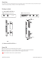
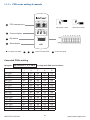
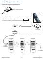
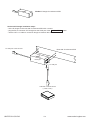
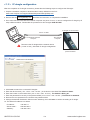
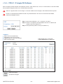
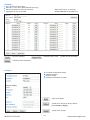
Intelligent Remote Power Management
User Manual
PPS-01, IP dongle GUI software
MTS switched PDU
MT monitored PDU
Designed and manufactured by Austin Hughes
UM-PPS-01-Q212V9
www.austin-hughes.com
Legal Information
First English printing, October 2002
Information in this document has been carefully checked for accuracy; however, no guarantee is given to the correctness
of the contents. The information in this document is subject to change without notice. We are not liable for any injury or
loss that results from the use of this equipment.
Safety Instructions
Please read all of these instructions carefully before you use the device. Save this manual for
future reference.
■
■
■
■
■
■
■
■
■
■
■
Unplug equipment before cleaning. Don’t use liquid or spray detergent; use a moist cloth.
Keep equipment away from excessive humidity and heat. Preferably, keep it in an air-conditioned environment with
temperatures not exceeding 40º Celsius (104º Fahrenheit).
When installing, place the equipment on a sturdy, level surface to prevent it from accidentally falling and causing dam
age to other equipment or injury to persons nearby.
When the equipment is in an open position, do not cover, block or in any way obstruct the gap between it and the
power supply. Proper air convection is necessary to keep it from overheating.
Arrange the equipment’s power cord in such a way that others won’t trip or fall over it.
If you are using a power cord that didn’t ship with the equipment, ensure that it is rated for the voltage and current
labeled on the equipment’s electrical ratings label. The voltage rating on the cord should be higher than the one listed
on the equipment’s ratings label.
Observe all precautions and warnings attached to the equipment.
If you don’t intend on using the equipment for a long time, disconnect it from the power outlet to prevent being dam
aged by transient over-voltage.
Keep all liquids away from the equipment to minimize the risk of accidental spillage. Liquid spilled on to the power
supply or on other hardware may cause damage, fire or electrical shock.
Only qualified service personnel should open the chassis. Opening it yourself could damage the equipment and invali
date its warranty.
If any part of the equipment becomes damaged or stops functioning, have it checked by qualified service personnel.
What the warranty does not cover
■
■
■
Any product, on which the serial number has been defaced, modified or removed.
Damage, deterioration or malfunction resulting from:
Accident, misuse, neglect, fire, water, lightning, or other acts of nature, unauthorized product modification, or
failure to follow instructions supplied with the product.
Repair or attempted repair by anyone not authorized by us.
Any damage of the product due to shipment.
Removal or installation of the product.
Causes external to the product, such as electric power fluctuation or failure.
Use of supplies or parts not meeting our specifications.
Normal wear and tear.
Any other causes which does not relate to a product defect.
Removal, installation, and set-up service charges.
□
□
□
□
□
□
□
□
Regulatory Notices Federal Communications Commission (FCC)
This equipment has been tested and found to comply with the limits for a Class B digital device, pursuant to Part 15 of the
FCC rules. These limits are designed to provide reasonable protection against harmful interference in a residential installation.
Any changes or modifications made to this equipment may void the user’s authority to operate this equipment. This
equipment generates, uses, and can radiate radio frequency energy and, if not installed and used in accordance with the
instructions, may cause harmful interference to radio communications.
However, there is no guarantee that interference will not occur in a particular installation. If this equipment does cause
harmful interference to radio or television reception, which can be determined by turning the equipment off and on, the
user is encouraged to try to correct the interference by one or more of the following measures:
■ Re-position or relocate the receiving antenna.
■ Increase the separation between the equipment and receiver.
■ Connect the equipment into an outlet on a circuit different from that to which the receiver is connected.
The company reserves the right to modify product specifications without prior notice and assumes no responsibility for any error which may appear in
this publication.
All brand names, logo and registered trademarks are properties of their respective owners.
Copyright 2011 Austin Hughes Electronics Ltd. All rights reserved.
UM-PPS-01-Q212V9
www.austin-hughes.com
Unpacking
The equipment comes with the standard parts shown on the package contents. Check and make sure they are included and in good
condition. If anything is missing, or damage, contact the supplier immediately.
Package contents
( 1 ) Vertical MTS / MT PDU x 1
- VMS mounting screw, set of 2 or 3
+
- VMB mounting bracket set
2 - 3 sets
M4
PEG
M4 x 2
Bracket x 2
M6
M6 x 2
M6 nut x 2
M6 nut
M4
OUT
IN
CUR
REN
22
5
T (A
)
ON
DIP
1
2
3
4
5
RES
6
7
8
ET
OUT
IN
CUR
REN
22
5
T (A
)
ON
DIP
1
2
3
4
5
RES
6
7
8
ET
M4
M6 nut
M6
OR
( 2 ) Rackmount MTS / MT PDU x 1
Power ON
■ Connect the PDU into an appropriately rated receptacle
■ When the PDU is power on, the LED display will light up. That means all outlets are activated
■ Keep the equipments in the power off position until it is plugged into the PDU
Don’t exceed the outlet, branch or phase limitations
UM-PPS-01-Q212V9
www.austin-hughes.com
Content
< 1.1 > PDU meter setting & cascade
P. 1 - 2
< 1.2 > IP dongle installation & connection
P. 3 - 4
< 1.3 > IP dongle configuration
P. 5
< 1.4 > PPS-01 IP dongle GUI Software
P. 6 - 7
UM-PPS-01-Q212V9
www.austin-hughes.com
< 1.1 > PDU meter setting & cascade
LINK
1
OUT
PDU cascade port
DIP Switch <ON>
DIP Switch <OFF>
CURRENT (A)
2
Current display
3
Dip switch
225
ON
1
4
DIP
2
3
4
5
6
7
8
Reset button
RESET
■
For rackmount PDU,
2
3
4
on the front panel left ,
1
on the rear panel
Cascaded PDUs setting
Using the
dip switch no. 1, 2, 3, 4 & 8
Cascaded PDUs
1st PDU
2nd PDU
3rd PDU
4th PDU
5th PDU
6th PDU
7th PDU
8th PDU
9th PDU
10th PDU
11th PDU
12th PDU
13th PDU
14th PDU
15th PDU
16th PDU
UM-PPS-01-Q212V9
1
On
Off
On
Off
On
Off
On
Off
On
Off
On
Off
On
Off
On
Off
to setup each PDU level as below :
Dip switch no.
2
3
4
On
On
On
On
On
On
Off
On
On
Off
On
On
On
Off
On
On
Off
On
Off
Off
On
Off
Off
On
On
On
Off
On
On
Off
Off
On
Off
Off
On
Off
On
Off
Off
On
Off
Off
Off
Off
Off
Off
Off
Off
P.1
8
Off
Off
Off
Off
Off
Off
Off
Off
Off
Off
Off
Off
Off
Off
Off
Off
www.austin-hughes.com
1st level PDU
LINK
2nd level PDU
CAT. 5 / 6
cable
OUT
LINK
Up to 20 meters
CURRENT (A)
IP dongle
( refer to P.3 - 9 )
1
2
3
4
5
6
7
ON
8
1
RESET
■
■
■
LINK
Up to 20 meters
2
3
4
5
6
225
DIP
ON
8
1
7
RESET
DIP
ON
OUT
CURRENT (A)
225
DIP
ON
CAT. 5 / 6
cable
OUT
CURRENT (A)
225
ON
3rd level PDU
DIP
2
3
4
5
6
7
To LINK port
of next PDU
( Up to 16 levels )
8
RESET
DIP
ON
DIP
1 2 3 4 5 6 7 8
1 2 3 4 5 6 7 8
1 2 3 4 5 6 7 8
Dip switch setting
Dip switch setting
Dip switch setting
The PDU can be cascaded up to 16 levels
For IP PDU access simply connect 1 x IP dongle - IPD-01
1 x IP dongle allows access to 16 levels
Meter display setting
Using the
dip switch no. 5 & 7
to setup each PDU meter display as below :
Current display
Circuit A + Circuit B
Circuit A only
Circuit B only
Dip switch no.
5
Off
On
On
7
Off
Off
On
Audio alarm
Using the
dip switch no. 6
to setup each PDU audio alarm as below :
Dip switch 6
Off
On
Enable
Disable
UM-PPS-01-Q212V9
P.2
www.austin-hughes.com
< 1.2 > IP dongle installation & connection
To remote PDU over IP, users can order IP dongle :
IPD-01 IP dongle for vertical PDU
Vertical IP dongle installation steps :
- slide the IP dongle on the plate above the meter
- plug the RJ-45 connector of IP dongle into the LINK port of the 1st level PDU
meter
- use the CAT. 5 / 6 cable to connect IP dongle to network device
To LAN port
Customer’s network device
( router or hub )
IP dongle
■
1st level PDU
LINK
To LINK port
of the 1st PDU
OUT
CURRENT (A)
225
ON
1
2
3
4
5
6
7
RESET
UM-PPS-01-Q212V9
Please refer dip switch setting on P.1 - 2 for different level PDUs
2nd level PDU
CAT. 5 / 6
cable
Up to 20 meters
LINK
OUT
CURRENT (A)
225
DIP
ON
8
1
2
3
4
5
6
7
RESET
P.3
3rd level PDU
CAT. 5 / 6
cable
Up to 20 meters
LINK
OUT
CURRENT (A)
225
DIP
ON
8
1
DIP
2
3
4
5
6
7
RESET
8
To LINK port
of next PDU
( Up to 16 levels )
www.austin-hughes.com
IPD-H01 IP dongle for rackmount PDU
Horizontal IP dongle installation steps :
- fix the IP dongle on the rear side of rackmount PDU with 4 screws
- plug the RJ-45 connector of IP dongle into the LINK port of the 1st level PDU
meter
- use the CAT. 5 / 6 cable to connect IP dongle to network device
To LINK port of the 1st PDU
Rear side of rackmount PDU
IP dongle
To LAN port
Customer’s network device
( router or hub )
UM-PPS-01-Q212V9
P.4
www.austin-hughes.com
< 1.3 > IP dongle configuration
After the completion of IP dongle connection, please take the following steps to configure the IP dongle :
1. Prepare a notebook computer to download the IP setup utilities from the link :
www.austin-hughes.com/support/utilities/infrapower/IPdongleSetup.msi
2. Double click the IPDongleSetup.msi
and follow the instruction to complete the installation.
3. Go to each first level PDU with the notebook computer & a piece of CAT. 5 / 6 cable to configure the IP dongle by IP
setup utilities as below. Please take the procedure for all IP dongles ONE BY ONE.
IP dongle on 1st level PDU
CAT. 5 / 6 cable
To notebook computer
LAN port
To IP dongle
LAN port
Reconnect the IP dongle with the network device
( router or hub ), after finish IP dongle configuration.
Ensure the PDU in
power ON status
4. Click Scan to search the connected IP dongles
5. Enter the device name ( min. 4 char. / max. 16 char. ) in the device name field. The default is Name.
6. Enter the location in the location field ( min. 4 char. / max. 16 char. ). The default is Rack_001.
7. Enter the password for security in the password field ( min. 8 char. / max. 16 char. ). The default is 00000000.
8. Re-enter the new password in the Confirm new password field.
9. Change the desired IP address / Subnet mask / Gateway, then click Save to confirm the setting to IP dongle.
10. The default IP address is as below:
IP address :
192.168.0.1
Subnet mask :
255.255.255.0
Gateway :
UM-PPS-01-Q212V9
192.168.0.254
P.5
www.austin-hughes.com
< 1.4 > PPS-01 IP dongle GUI Software
Each IP dongle provides a built-in GUI software, PPS-01, which allows user, via an I.E. web browser, to see PDU’s data
and remotely manage the PDU over a TCP/IP Ethernet network.
Each I.E. supports ONLY one IP dongle. If the user installs more IP dongles, multi windows will be required.
PPS-01 is a management software but with very limited features. The user can use advanced software,
InfraPower Manager IPM-01.
Step 1. Open Internet Explorer ( I.E. ), version 6.0 or above
Step 2. Enter the configured IP dongle address into the I.E. address bar
( Refer to set up IP utilities p.5 )
Step 3. Enter password ( Refer to set up IP utilities P.5 )
< Status >
Status of all connected PDUs
Aggregate current on each PDU
Latest loading on each circuit of PDU
Alarm threshold setup
- Data refresh every 10 seconds
- Disable Refresh during data input
: save the changes
: quit without changes
UM-PPS-01-Q212V9
P.6
www.austin-hughes.com
< Details >
On / Off status of each outlet
Remote on / off outlet ( MTS switched PDU only )
Rename outlet device, PDU and location
Aggregate current on the PDU
: save the changes
- Data refresh every 10 seconds
- Disable Refresh during data input
: restart the PDU meter
( outlets are still activated )
: reload the PDU information
< Setup >
IP dongle configuration setting
Password setting
Network setting
Hardware information provided
: save the changes
: reload the IP dongle to factory default
( Press Default > Apply )
: restart the IP dongle
UM-PPS-01-Q212V9
P.7
www.austin-hughes.com
The company reserves the right to modify product specifications without prior notice and assumes no responsibility
for any error which may appear in this publication.
All brand names, logo and registered trademarks are properties of their respective owners.
Copyright 2012 Austin Hughes Electronics Ltd. All rights reserved.
UM-PPS-01-Q212V9
www.austin-hughes.com