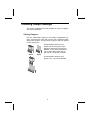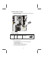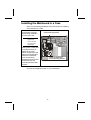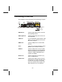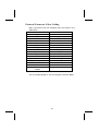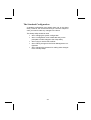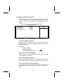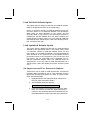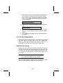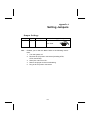
1
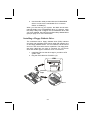
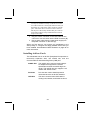
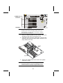
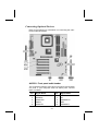
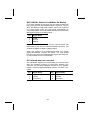
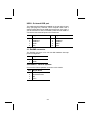
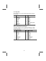
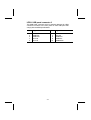
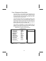
Preface
Copyright
This publication, including all photographs, illustrations and software,
is protected under international copyright laws, with all rights reserved. Neither this manual, nor any of the material contained herein,
may be reproduced without written consent of the author.
Version 1.0
Disclaimer
The information in this document is subject to change without notice.
The manufacturer makes no representations or warranties with respect to the contents hereof and specifically disclaims any implied
warranties of merchantability or fitness for any particular purpose.
The manufacturer reserves the right to revise this publication and to
make changes from time to time in the content hereof without obligation of the manufacturer to notify any person of such revision or
changes.
Trademark Recognition
Microsoft, MS-DOS and Windows are registered trademarks of Microsoft Corp.
MMX, Pentium, Pentium-II, Pentium-III, P4/Northwood, Celeron are
registered trademarks of Intel Corporation.
Other product names used in this manual are the properties of their
respective owners and are acknowledged.
Copyright © 2001
All Rights Reserved
KOB 845 NFSX
August 2001
Federal Communications Commission (FCC)
This equipment has been tested and found to comply with the limits
for a Class B digital device, pursuant to Part 15 of the FCC Rules.
These limits are designed to provide reasonable protection against
harmful interference in a residential installation. This equipment generates, uses, and can radiate radio frequency energy and, if not
installed and used in accordance with the instructions, may cause
harmful interference to radio communications. However, there is no
guarantee that interference will not occur in a particular installation. If
this equipment does cause harmful interference to radio or television
reception, which can be determined by turning the equipment off
and on, the user is encouraged to try to correct the interference by
one or more of the following measures:
−
Reorient or relocate the receiving antenna.
−
Increase the separation between the equipment and the
receiver.
−
Connect the equipment onto an outlet on a circuit different
from that to which the receiver is connected.
−
Consult the dealer or an experienced radio/TV technician
for help.
Shielded interconnect cables and a shielded AC power cable must
be employed with this equipment to ensure compliance with the pertinent RF emission limits governing this device. Changes or
modifications not expressly approved by the system's manufacturer
could void the user's authority to operate the equipment.
ii
Declaration of Conformity
This device complies with part 15 of the FCC rules. Operation is subject to the following conditions:
−
This device may not cause harmful interference, and
−
This device must accept any interference received, including interference that may cause undesired operation.
Canadian Department of Communications
This class B digital apparatus meets all requirements of the Canadian Interference-causing Equipment Regulations.
Cet appareil numérique de la classe B respecte toutes les exigences
du Réglement sur le matériel brouilieur du Canada.
iii
About the Manual
The manual consists of the following:
Chapter 1
Introducing the Mainboard
Describes features of the mainboard, and provides a shipping
checklist.
Go to ⇒ page 1
Chapter 2
Installing the Mainboard
Describes installation of mainboard components.
Go to ⇒ page 7
Chapter 3
Using BIOS
Provides information on using
the BIOS Setup Utility.
Go to ⇒ page 34
Chapter 4
Using the Mainboard Software
Describes the mainboard software.
Go to ⇒ page 63
Appendix A
Setting Jumpers
Provides a reference to the
jumpers on the mainboard.
Go to ⇒ page 67
iv
TABLE OF CONTENTS
Preface
i
CHAPTER 1
1
Introducing the Mainboard
1
Introduction ......................................................................................1
Checklist ..........................................................................................1
Standard Items ..................................................................................... 1
Features...........................................................................................2
Mainboard Components ..................................................................4
Choosing a Computer Case ............................................................6
CHAPTER 2
7
Installing the Mainboard
7
Safety Precautions...........................................................................7
Quick Guide .....................................................................................8
Checking Jumper Settings...............................................................9
Setting Jumpers ................................................................................... 9
Checking Jumper Settings ................................................................. 10
Jumper Settings ................................................................................. 10
Installing the Mainboard in a Case ................................................11
Connecting Case Components......................................................12
The Panel Connector ......................................................................... 13
Installing Hardware ........................................................................14
Installing the Processor...................................................................... 14
Installing Memory Modules .............................................................. 19
Installing a Hard Disk Drive/CD-ROM............................................. 21
Installing a Floppy Diskette Drive..................................................... 24
Installing Add-on Cards..................................................................... 25
Connecting Optional Devices............................................................ 27
Connecting I/O Devices.................................................................32
External Connector Color Coding ..................................................... 33
CHAPTER 3
34
Using BIOS
34
About the Setup Utility ...................................................................34
The Standard Configuration .............................................................. 35
Entering the Setup Utility .................................................................. 36
Updating the BIOS ............................................................................ 37
Using BIOS ....................................................................................39
v
Standard CMOS Features .................................................................. 39
Advanced BIOS Setup Option........................................................... 42
Advanced Chipset Features Option ................................................... 45
Integrated Peripherals Option............................................................ 48
Power Management Setup Option ..................................................... 52
PNP/PCI Configuration Option ......................................................... 57
PCI Health Status Option .................................................................. 59
Frequency/Voltage Control................................................................ 60
Load Fail-Safe Defaults Option......................................................... 61
Load Optimized Defaults Option ...................................................... 61
Set Supervisor and User Passwords Options ..................................... 61
Save & Exit Setup Option ................................................................. 62
Exit Without Saving .......................................................................... 62
CHAPTER 4
63
Using the Mainboard Software
63
About the Software CD-ROM ........................................................63
Drivers Installation .........................................................................63
Utility Folder Installation Notes ......................................................65
Award Flash Memory Utility............................................................. 65
PC-cillin Software ............................................................................. 65
CD-Ghost........................................................................................... 65
Recovery Genius ............................................................................... 66
WinDVD (optional)........................................................................... 66
APPENDIX A
67
Setting Jumpers
67
Jumper Settings ................................................................................. 67
The Panel Connector ......................................................................... 68
vi
Chapter 1
Introducing the Mainboard
Introduction
Congratulations on purchasing the KOB 845 NFSX mainboard. The KOB 845 NFSX mainboard is an ATX mainboard
that uses a 4-layer printed circuit board and measures 304
mm x 244 mm. The mainboard features a mPGA478 socket
that accommodates Intel Pentium 4 processors supporting
system speeds up to 400 MHz and data bus bandwidths up to
3.2 GB/s.
The KOB 845 NFSX incorporates the Intel i82845 (MCH) and
the Intel 82801BA (ICH2) chipsets, which supports 3.3V DIMM
DRAM, 2X/4X AGP (1.5V only), and the AC 97 codec.
Checklist
Compare the mainboard’s package contents with the following
checklist:
Standard Items
•
•
•
•
•
•
One mainboard
One diskette drive ribbon cable and bracket
One IDE drive ribbon cable and bracket
One auto-install software support CD
Retention modules (already mounted on the board)
This user’s manual
Features
Processor
Chipset
The KOB 845 NFSX mainboard uses an
mPGA478 socket that has the following features:
• Accommodates Intel Pentium 4 CPUs
• Supports a system bus of 400 MHz
• Supports a 3.2 GB/s data bus bandwidth
Intel’s innovative i82845 (MCH) and 82801BA
(ICH2) chipsets are based on an innovative and
scalable architecture with proven reliability and
performance. A few of the advanced features of
the chipsets are:
•
Host interface controller supports 400 MHz
frontside (system) bus frequency
• Supports up to 3 GB of DRAM
• Supports a maximum memory bandwidth of 1
GB/s
• AGP controller is AGP 2.0 compliant and supports 2x/4x Fast Write Protocol (1.5V only)
• PCI IDE controller supports PCI bus mastering, PIO modes 0~4, and UDMA 33/66/100
• Four USB 1.1 ports for serial transfer at 1.2 or
1.5 Mbit/sec.
• Integrated AC 97 audio that supports full surround sound with up to six channels
Additional key features include support for an AC 97
link for audio and modem, hardware monitoring, and
ACPI/OnNow power management.
Memory
The mainboard can accommodate 3.3V, unbuffered, 168 pin DIMM DRAM with a total
capacity of 3 GB.
VGA
The KOB 845 NFSX includes a 4xAGP slot that provides four times the bandwidth of the original AGP
specification. AGP technology provides a direct connection between the graphics sub-system and the
processor so that the graphics do not have to compete for processor time with other devices on the
PCI bus.
2
AC 97 Audio
Codec
The AC 97 Audio codec is compliant with the AC
97 2.2 specification, and supports 18-bit ADC
(Analog Digital Converter) and DAC (Digital Analog Converter) resolution as well as 18-bit stereo
full-duplex codec with independent and variable
sampling rates.
Expansion
Options
The mainboard comes with the following expansion options:
•
•
•
Six 32-bit PCI slots
One 4xAGP slot
One Communications Network Riser (CNR)
slot
• Two IDE channels and a floppy disk drive
interface
• One Onboard LAN chip and LAN port on top
of the USB port (optional)
The KOB 845 NFSX supports Ultra DMA bus
mastering with transfer rates of 33/66/100
MB/sec.
Integrated I/O
BIOS
Firmware
The mainboard has a full set of I/O ports and connectors:
• Two PS/2 ports for mouse and keyboard
• Two serial ports
• One parallel port
• One MIDI/game port
• Two USB ports
• One LAN port (optional)
• Audio jacks for microphone, line-in and line-out
This mainboard uses Award BIOS that enables
users to configure many system features including
the following:
• Power management
• Wake-up alarms
• CPU parameters and memory timing
• CPU and memory timing
The firmware can also be used to set parameters
for different processor clock speeds.
3
Mainboard Components
4
Table of Mainboard Components
Label
AGP1
ATX1
ATX2
ATX3
AUDIO1
BAT1
CASFAN1
CDIN1
CDIN2
CNR1
CPU Socket
CPUFAN1
DIMM1 ~ DIMM3
FDD1
IDE 1
IDE 2
IR1
J1
J2
JP1
LED1
LEG1
LEG2
PANEL1
PCI1 ~ PCI6
PFAN1
SPEAKER1
USB1
VID0-VID4
WOL1
WOR1
Component
Accelerated Graphics Port
Standard 20-pin ATX power connector
Aux Vcc and Vcc3 6-pin ATX power connector
+12 VDC 2 x 2 ATX power connector
Microphone and speaker-out header
Three volt realtime clock battery
Case Fan
CD-in connector (Panasonic)
CD-in connector (Sony)
Communications Networking Riser slot
CPU socket (mPGA478)
Cooling fan for CPU
Three 168-pin DIMM sockets 3.3 volt
Floppy disk drive connector
Primary IDE channel
Secondary IDE channel
IR connector
ExtSMI connector
Smart I/O
Clear CMOS jumper
LED status indicator connector
Front panel connector 2
USB connector 2
Front panel connectors for suspend LED, HDD
LED, power switch and H/W reset.
Six 32-bit add-on card slots
Power fan connector
Speaker connector
Front panel USB headers
Core voltage selector jumpers
Wake On LAN wakeup connector
Wake On Ring wakeup connector
Note: LED1 - This red indicator warns you that the computer is still powered on and you should not install
or uninstall memory modules.
5
Choosing a Computer Case
There are many types of computer cases on the market. The
mainboard complies with the specifications for the ATX system case. Some features on the mainboard are implemented
by cabling connectors on the mainboard to indicators and
switches on the system case. Ensure that your case supports
all the features required. The mainboard can support one
floppy diskette drives and four enhanced IDE drives. Ensure
that your case has sufficient power and space for all the drives
that you intend to install.
Most cases have a choice of I/O templates in the rear panel.
Make sure that the I/O template in the case matches the I/O
ports installed on the rear edge of the mainboard.
This mainboard has a ATX form factor of 304 mm x 244 mm.
Choose a case that accommodates this form factor.
This concludes Chapter 1. The next chapter explains how to
install the mainboard.
6
Chapter 2
Installing the Mainboard
Safety Precautions
Follow these safety precautions when installing the mainboard:
•
•
•
•
Wear a grounding strap attached to a grounded device
to avoid damage from static electricity.
Discharge static electricity by touching the metal case
of a safely grounded object before working on the
mainboard.
Leave components in the static-proof bags they came
in.
Hold all circuit boards by the edges. Do not bend circuit boards.
Quick Guide
This Quick Guide suggests the steps you can take to assemble your system with the mainboard.
The following table provides a reference for installing specific
components:
Locating Mainboard Components
Go to page 4
Setting Jumpers
Go to page 9
Installing the Mainboard in a Case
Go to page 11
Installing Case Components
Go to page 12
Installing the CPU
Go to page 14
Installing Memory
Go to page 19
Installing an HDD and CD-ROM Drive
Go to page 21
Installing an FDD
Go to page 24
Installing Add-on Cards
Go to page 25
Connecting Options
Go to page 27
Connecting Peripheral (I/O) Devices
Go to page 32
Note: The appendix provides a quick reference for jumper
settings.
8
Checking Jumper Settings
This section explains how to set jumpers for correct configuration of the mainboard.
Setting Jumpers
Use the mainboard jumpers to set system configuration options. Jumpers with more than one pin are numbered. When
setting the jumpers, ensure that the jumper caps are placed
on the correct pins.
This illustration shows a 2-pin
jumper. When the jumper cap is
placed on both pins, the jumper is
SHORT. If you remove the jumper
cap, or place the jumper cap on
just one pin, the jumper is OPEN.
Short
Open
This illustration shows a 3-pin
jumper. Pins 1 and 2 are SHORT.
1 2
3
9
Checking Jumper Settings
DIMM1
The following illustration shows the location of the mainboard
jumpers. Pin 1 is labeled.
DIMM2
DIMM3
CPUFAN1
ATX3
ATX2
ATX1
CASFAN1
LED1
1
1
1
JP1
CDIN1 CDIN2
PFAN1
AGP1
IDE1
IDE2
LEG1
FDD1
AUDIO1
WOL1
PCI1
WOM1
PCI2
JP1
1
1
1
1
1
1
VID4
VID3
VID2
VID1
VID0
J1
BT1
1
PCI4
SPEAKER1
PCI3
J2
1
PCI5
PANEL1
1
IR1
1
USB1
PCI6
1
CNR1
1
LEG2
Jumper Settings
Jumper
Type
Description
JP1
3-pin
Clear CMOS
Setting (default)
1-2: Normal
2-3: Clear
1
JP1
JP1 – Enables you to clear the BIOS. Refer to the following instructions:
1. Turn the system off.
2. Remove all ATX power connectors (including ATX1,
ATX2, and ATX3).
3. Short pins 2 and 3 on JP1.
4. Return the jumper to the normal setting.
5. Plug in all ATX power connectors
10
Installing the Mainboard in a Case
Refer to the following illustration and instructions for installing
the mainboard in a case:
This illustration shows
an example of a mainboard being installed in
a tower-type case:
2. Secure the mainboard with
screws where appropriate.
Note: Do not overtighten the
screws as this
can stress the
mainboard.
Most system cases have
mounting brackets installed in the case,
which correspond to the
holes in the mainboard.
Place the mainboard
over the mounting
brackets and secure the
mainboard onto the
mounting brackets with
screws.
1. Place the mainboard
over the mounting brackets.
Ensure that your case has an I/O template that supports the
I/O ports and expansion slots on your mainboard.
11
Connecting Case Components
After you have installed the mainboard into a case, you can
begin connecting the mainboard components.
CPUFAN1
DIMM1
CASFAN1
DIMM2
DIMM3
CPUFAN1
CASFAN1
LED1
ATX1
ATX1
ATX2
ATX3
ATX2
ATX3
1
1
IDE1
IDE2
AGP1
FDD1
AUDIO1
LEG1
CDIN1 CDIN2
PFAN1
PFAN1
WOL1
PCI1
WOM1
PCI2
JP1
1
1
1
1
1
1
VID4
VID3
VID2
VID1
VID0
J1
BT1
1
PCI4
SPEAKER1
PCI3
J2
1
PANEL1
1
PCI5
PANEL1
1
IR1
1
USB1
PCI6
1
CNR1
1
LEG2
1. Supply power to the mainboard using the three ATX
connectors (compliant with ATX 2.03 specifications).
• Connect the 20-pin power supply connector to
ATX1 (connection is required).
• Connect the 6-pin Vcc/Vcc3 ATX power supply
connector to ATX2 (connection is optional).
• Connect the 2 x 2-pin +12 VDC ATX power supply
connector to ATX3 (connection is required).
Note: When the system is heavily loaded, you should
install, at a minimum, an ATX12V power supply with a 300W capacity.
12
2. Connect the CPU cooling fan cable to CPUFAN1.
3. Connect the case cooling fan connector to CASFAN1
4. Connect the auxiliary power supply cooling fan connector to PFAN1.
5. See next page for PANEL1 pin descriptions.
The Panel Connector
The panel connector provides a set of switch and LED connectors commonly found on ATX or Micro ATX cases. Refer to
the table below for information:
Device
Empty
N/C
Power
ON/OFF
Reset
Switch
Green LED
Indicator
HDD LED
Pins
10
9
6, 8
1
2
HDD LED
(Pins 1, 3)
Green LED
(Pins 2, 4)
Reset Switch
(Pins 5, 7)
Power Switch
(Pins 6, 8)
5, 7
+2, -4
+1, -3
N/C
(Pin 9)
Empty
(Pin 10)
9
10
Note: The plus sign (+) indicates a pin which must be connected to a positive voltage.
13
Installing Hardware
Installing the Processor
Caution: When installing a CPU heatsink and cooling fan
make sure that you DO NOT scratch the mainboard or any
of the surface-mount resistors with the clip of the cooling
fan. If the clip of the cooling fan scrapes across the mainboard, you may cause serious damage to both the
mainboard or its components.
On most mainboards, there are small surface-mount resistors near the processor socket, which may be damaged if
the cooling fan is carelessly installed.
Avoid using cooling fans with sharp edges on the fan casing
and the clips. Also, install the cooling fan in a well-lit work
area so that you can clearly see the mainboard and processor socket.
Before installing the Processor
This mainboard automatically determines the CPU clock frequency and system bus frequency for the processor. You may
be able to change these settings through the BIOS Setup Utility. We strongly recommend that you do not overclock
processors or other components to run faster than their rated
speed.
Warning: Overclocking components can adversely affect
the reliability of the system and introduce errors into your
system. Overclocking can permanently damage the mainboard by generating excess heat in components that are
run beyond the rated limits.
14
This mainboard has an mPGA478B socket. When choosing a
processor, consider the performance requirements of the system. Performance is based on the processor design, the clock
speed and system bus frequency of the processor, and the
quantity of internal cache memory and external cache memory.
CPU Installation Procedure
The following illustration shows CPU installation components:
CPU fan
Retention modules
Locking lever
Pin-1 corner
mPGA478B Socket
Note: The pin-1 corner is marked with an arrow
15
Follow these instructions to install the CPU:
1. Pull the CPU socket locking lever away from the
socket to unhook it and raise the locking lever to the
upright position.
2. Match the corner on the CPU marked with an arrow
with pin-1 on the CPU socket (the corner with the pinhole noticeably missing). Insert the processor into the
socket. Do not use force.
Locking lever
Pin-1
corners
3. Swing the locking lever down and hook it under the
latch on the edge of the socket.
4. Apply thermal grease to the top of the CPU.
16
CPU Fan Power Cable
CPU Fan
Heatsink
5. Lower the heatsink over the CPU.
6. Lower the CPU cooling fan onto the heatsink.
7. Snap the four retention legs of the cooling fan into
place (see diagram below).
Cooling Fan
Heatsink
Retention Module
17
8. Swing both lock levers on top of the cooling fan to their
opposite side to secure the cooling fan on top of the
heatsink.
9. Connect the CPU Cooling Fan power cable to the
CPUFAN1 connector.
CPU fan connector
CPUFAN1
Note: CPU fan and heatsink installation procedures may
vary with the type of CPU fan/heatsink supplied.
The form and size of fan/heatsink may also vary.
18
Installing Memory Modules
For this mainboard, you must use 168-pin 3.3V non-buffered
Dual In-line Memory Modules (DIMMs). The memory chips are
standard SDRAM (Synchronous Dynamic Random Access
Memory). The table below shows the supported frequencies.
Frontside Bus
(FSB)
Frequency
100 MHz
100 MHz
System Memory
Bus (SMB)
Frequency
100 MHz
133 MHz
Installation Procedure
The mainboard accommodates three memory modules. You
must install at least one module in any of the three slots. Each
module can be installed with 64 MB to 512 MB of memory. Total capacity is 3GB.
1. Align the memory module with the slot. The DIMM
slots are keyed with notches and the DIMMs are keyed
with cutouts so that they can only be installed correctly. Check that the cutouts on the DIMM module
edge connector match the notches in the DIMM slot:
19
Latch
Cutouts
Notches
Latch
2. Push the latches on each side of the DIMM slot down.
3. Install the DIMM module into the slot and press it firmly
down so that it seats correctly. The slot latches are
levered upwards and latch on to the edges of the
DIMM when it is installed correctly.
Latch
Cutout
Notch
Latch
20
Installing a Hard Disk Drive/CD-ROM
This section describes how to install IDE devices such as a
hard disk drive and a CD-ROM drive.
About IDE Devices
Your mainboard has a primary and secondary IDE channel interface (IDE1 and IDE2). An IDE ribbon cable supporting two IDE
devices is bundled with the mainboard.
If you want to install more than two IDE devices, get a second
IDE cable and you can add two more devices to the secondary IDE channel.
IDE devices have jumpers or switches that are used to set the
IDE device as MASTER or SLAVE. Refer to the IDE device
user’s manual. When installing two IDE devices on one cable,
ensure that one device is set to MASTER and the other device is set to SLAVE. The documentation of your IDE device
explains how to do this.
About UltraDMA
This mainboard supports UltraDMA 33/66/100. UDMA is a
technology that accelerates the performance of devices in the
IDE channel. To maximize performance, install IDE devices
that support UDMA and use 80-pin IDE cables that support
UDMA 66/100.
21
Installing a Hard Disk Drive
1. Install the hard disk drive into the drive cage in your
Micro ATX system case.
2. Plug the IDE cable into IDE1 (A):
HDD
B
C
Colored
stripe
A
Pin 1
Note: The ribbon cable connectors are keyed so that they
can only be installed correctly on the device connector. If the connector is not keyed, make sure that you
match the pin-1 side of the cable connector with the
pin-1 side of the device connector. Each connector
has the pin-1 side clearly marked. The pin-1 side of
each ribbon cable is always marked with a colored
stripe on the cable.
3. Plug an IDE cable connector into the hard disk drive
IDE connector (B). It doesn't matter which connector
on the cable you use.
4. Plug a power cable from the case power supply into
the power connector on the hard disk drive (C).
When you first start up your system, the BIOS should automatically detect your hard disk drive. If it doesn’t, enter the
Setup Utility and use the IDE Hard Disk Auto Detect feature to
configure the hard disk drive that you have installed. See IDE
HDD Auto-Detection on page 40 for more information.
22
Installing a CD-ROM/DVD Drive
1. Install the CD-ROM/DVD drive into the drive cage in
your Micro ATX system case.
2. Plug the IDE cable into IDE1 (A). If you have already
installed an HDD, use the other connector on the IDE
cable.
CD-ROM
CD-ROM audio
connector
C
B
Colored
stripe
A
Pin 1
D
CDIN1
CDIN2
Note: The ribbon cable connectors are keyed so that they can only
be installed correctly on the device connector. If the connector is not keyed, make sure that you match the pin-1 side of
the cable connector with the pin-1 side of the device connector. Each connector has the pin-1 side clearly marked. The
pin-1 side of each ribbon cable is always marked with a colored stripe on the cable.
3. Plug an IDE cable connector into the CD-ROM/DVD
drive IDE connector (B). It doesn't matter which connector on the cable you use.
4. Plug a power cable from the case power supply into
the power connector on the CD-ROM/DVD drive (C).
23
5. Use the audio cable provided with the CD-ROM/DVD
drive to connect to the mainboard CD-in connector
CDIN1 or CDIN2 (D).
When you first start up your system, the BIOS should automatically detect your CD-ROM/DVD drive. If it doesn’t, enter
the Setup Utility and configure the CD-ROM/DVD drive that
you have installed. See IDE Primary/Secondary Master/Slave
(Auto)on page 41 for more information.
Installing a Floppy Diskette Drive
The mainboard has a floppy diskette drive (FDD) interface
and ships with a diskette drive ribbon cable that supports one
or two floppy diskette drives. You can install a 5.25-inch drive
and a 3.5-inch drive with various capacities. The floppy diskette drive cable has one type of connector for a 5.25-inch
drive and another type of connector for a 3.5-inch drive.
1. Install the FDD into the drive cage in your Micro ATX
system case.
2. Plug the FDD cable into FLOPPY1 (A):
FDD
B
Colored
stripe
C
A
Pin 1
24
Note: The ribbon cable connectors are keyed so that they
can only be installed correctly on the device connector. If the connector is not keyed, make sure that you
match the pin-1 side of the cable connector with the
pin-1 side of the device connector. Each connector
has the pin-1 side clearly marked. The pin-1 side of
each ribbon cable is always marked with a colored
stripe on the cable.
3. Plug the correct connector on the FDD cable for the
5.25-inch or 3.5-inch drive into the FDD connector (B).
4. Plug a power cable from the case power supply into
the power connector on the FDD (C).
When you first start up your system, go immediately to the
Setup Utility to configure the floppy diskette drives that you
have installed. See Standard CMOS Features on page 39 for
more information.
Installing Add-on Cards
This mainboard has six 32-bit PCI (Peripheral Components Interconnect) expansion slots, one 4xAGP slot, and one
Communications and Networking Riser (CNR) slot.
4xAGP Slot
The 4xAGP slot is used to install a graphics adapter that supports the 4xAGP
specification and has a 4xAGP edge connector. The 4xAGP slot only supports 1.5V
4xAGP and 2xAGP cards.
PCI Slots
PCI slots are used to install expansion
cards that have the 32-bit PCI interface.
CNR Slot
This slot is used to insert CNR cards including LAN, Modem, and Audio functions.
25
CDIN1 CDIN2
WOL1
PCI1
WOM1
PCI2
1
JP1
BT1
FDD1
1
1
1
1
1
VID4
VID3
VID2
VID1
VID0
PCI3
1
PCI4
SPEAKER1
J1
PCI Slots
PFAN1
AGP1
IDE1
IDE2
LEG1
4xAGP Slot
J2
1
PCI5
PANEL1
1
IR1
1
USB1
PCI6
1
CNR1
CNR Slot
1
LEG2
Note: Before installing an add-on card, check the documentation for the card carefully. If the card is not
Plug and Play, you may have to manually configure
the card before installation.
1. Remove a blanking plate from the system case corresponding to the slot you are going to use.
2. Install the edge connector of the add-on card into the
expansion slot. Ensure that the edge connector is correctly seated in the slot.
Add-on
card
Edge connector
3. Secure the metal bracket of the card to the system
case with a screw.
Note: For some add-on cards, for example graphics adapters
and network adapters, you have to install drivers and
software before you can begin using the add-on card.
26
Connecting Optional Devices
Refer to the following for information on connecting the mainboard’s optional devices:
AUDIO1: Front panel audio header
This mainboard supports front panel microphone and speaker
out ports. If your computer case has these ports, connect
them to AUDIO1.
Pin
1
3
5
7
9
Signal Name
Pin
Signal Name
MICIN
MICBIAS
SPKOUTR
EMPTY
SPKOUTL
2
4
6
8
10
AGND
5V
XSPKOUTR
KEY
XSPKOUTL
27
WOL1/WOR1: Wake On LAN/Wake On Modem
If you have installed a LAN card, use the cable provided with
the card to plug into the mainboard WOL1 connector. This enables the Wake On LAN (WOL) feature. When your system is
in a power-saving mode, any LAN signal automatically resumes the system. You must enable this item using the Power
Management page of the Setup Utility.
Pin
1
2
3
Signal Name
5VSB
Ground
SENSE
If you have installed a modem, use the cable provided with
the modem to plug into the mainboard WOM1 connector. This
enables the Wake On Modem (WOR) feature.
When your system is in a power-saving mode, any modem
signal automatically resumes the system. You must enable
this item using the Power Management page of the Setup Utility. See Chapter 3 for more information.
IR1: Infrared data port connector
The mainboard supports an infrared data port. Infrared ports
allow the wireless exchange of information between your
computer and similarly equipped devices such as printers,
laptops, Personal Digital Assistants (PDAs), and other computers.
Pin
1
3
5
Signal Name
Pin
NC
+5VDC
IR transmit
2
4
6
28
Signal Name
Key
Ground
IR receive
USB1: On board USB port
The mainboard has USB ports installed on the rear edge I/O port
array (see page 32). However, some computer cases have a
special module that mounts USB ports at the front of the case. If
you have this kind of case, use auxiliary USB connector USB1 to
connect the front-mounted ports to the mainboard.
Pin
1
3
5
7
9
Signal Name
Pin
Signal Name
VCC
USBP2-N
USBP2-P
GND
Key
2
4
6
8
10
VCC
USBP3-N
USBP3-P
GND
OC#
J1: ExtSMI connector
The ExtSMI connector is for use with SMI hardware interrupt
power management.
Pin
1
2
Signal Name
EXTSMI
GND
SPEAKER1: Internal speaker
Connect the internal speaker connector to this header.
Pin
1
2
3
4
Signal Name
External speaker
Onboard buzzer
NC
VCC
29
J2: Smart I/O
This connector is for use with media storage devices using the
LPC interface.
Pin
Signal Name
Pin
Signal Name
1
2
3
4
5
6
7
8
9
10
PCICLK
SERIRQ
LFRAME#
LDRQ#
LAD0
LAD1
LAD2
LAD3
PCIRST#
PME#
11
12
13
14
15
16
17
18
19
20
VCC3
VCC3
GND
GND
5VSB
GND
GND
RESERVED(GND)
VCC5
VCC5
LEG1: Audio Panel connector 2
This panel connector which is specially designed for OEM
customers provides a set of switches and connectors using
the OEM specification.
Pin
Signal Name
Pin
Signal Name
1
3
5
7
9
11
13
15
ALOR
AGND
Ground
+12V
MIC
SPKOUTR
SPKOUTL
AGND
2
4
6
8
10
12
14
16
ALOL
AGND
Ground
Empty
AGND
XSPKOUTR
XSPKOUTL
Empty
30
LEG2: USB panel connector 2
This USB panel connector which is specially designed for OEM
customers connects to the front panel or case USB ports that
comply with the OEM specifications.
Pin
1
3
5
7
9
Signal Name
Pin
Signal Name
USBPWR
USBPP2USBPP2+
Ground
Ground
2
4
6
8
10
Ground
Ground
USBPP3+
USBPP3USBPWR2
31
Connecting I/O Devices
The backplane of the mainboard has the following I/O ports:
PS/2
mouse
PS/2
keyboard
LAN
port
USB
ports
Parallel port (LPT1)
Serial port Serial port
COM 1
COM 2
Game port
Microphone
Line-in
Line-out
PS/2 Mouse
Use the upper PS/2 port to connect a
PS/2 pointing device.
PS/2 Keyboard
Use the lower PS/2 port to connect a
PS/2 keyboard.
LAN Port
If your mainboard comes with the LAN
option, you can connect an RJ-45 cable to the LAN port.
USB Ports
Use the USB ports to connect USB
devices.
LPT1
Use LPT1 to connect printers or other
parallel communications devices.
COM1/2
Use the COM ports to connect serial
devices such as mice or fax/modems.
COM1 is identified by the system as
COM1/3. COM2 is identified by the
system as COM2/4.
Game Port
Use the game port to connect a joystick or a MIDI device.
Audio Ports
Use the three audio ports to connect
audio devices. The left side jack is for
a stereo line-out signal. The middle
jack is for a stereo line-in signal. The
right side jack is for a microphone.
32
External Connector Color Coding
Many connectors now use standard colors as shown in the
table below.
Connector
Analog VGA
Audio line-in
Audio line-out
Digital monitor/flat panel
IEEE 1394
Microphone
MIDI/game
Parallel
PS/2-compatible keyboard
PS/2-compatible mouse
Serial
Speaker out/subwoofer
Right-to-left speaker
USB
Video out
SCSI, network, telephone,
modem
Color
Blue
Light blue
Lime
White
Grey
Pink
Gold
Burgundy
Purple
Green
Teal or Turquoise
Orange
Brown
Black
Yellow
None
This concludes Chapter 2. The next chapter covers the BIOS.
33
Chapter 3
Using BIOS
About the Setup Utility
The computer uses the latest Award BIOS with support for
Windows Plug and Play. The CMOS chip on the mainboard
contains the ROM setup instructions for configuring the mainboard BIOS.
The BIOS (Basic Input and Output System) Setup Utility displays the system's configuration status and provides you with
options to set system parameters. The parameters are stored
in battery-backed-up CMOS RAM that saves this information
when the power is turned off. When the system is turned back
on, the system is configured with the values you stored in
CMOS.
The BIOS Setup Utility enables you to configure:
•
•
•
•
Hard drives, diskette drives, and peripherals
Video display type and display options
Password protection from unauthorized use
Power management features
The settings made in the Setup Utility affect how the computer
performs. Before using the Setup Utility, ensure that you understand the Setup Utility options.
This chapter provides explanations for Setup Utility options.
The Standard Configuration
A standard configuration has already been set in the Setup
Utility. However, we recommend that you read this chapter in
case you need to make any changes in the future.
This Setup Utility should be used:
•
•
•
•
•
when changing the system configuration
when a configuration error is detected and you are
prompted to make changes to the Setup Utility
when trying to resolve IRQ conflicts
when making changes to the Power Management configuration
when changing the password or making other changes
to the Security Setup
35
Entering the Setup Utility
When you power on the system, BIOS enters the Power-On
Self Test (POST) routines. POST is a series of built-in diagnostics performed by the BIOS. After the POST routines are
completed, the following message appears:
Press DEL to enter SETUP
Pressing the delete key
Utility:
accesses the Award BIOS Setup
CMOS Setup Utility – Copyright (C) 1984 – 2001 Award Software
Standard CMOS Features
Frequency/Voltage Control
Advanced BIOS Features
Load Fail-Safe Defaults
Advanced Chipset Features
Load Optimized Defaults
Integrated Peripherals
Set Supervisor Password
Power Management Setup
Set User Password
PnP/PCI Configurations
Save & Exit Setup
Exit Without Saving
PC Health Status
↑ ↓ → ← :
Esc : Quit
F10 : Save & Exit Setup
Select Item
Time, Date, Hard Disk Type . . .
BIOS Navigation Keys
The BIOS navigation keys are listed below:
Key
Esc
←↑↓→
+/–
/PU/PD
F10
F1
F5
F6
F7
Function
Exits the current menu
Scrolls through the items on a menu
Modifies the selected field's values
Saves the current configuration and exits setup
Displays a screen that describes all key functions
Loads previously saved values to CMOS
Loads a minimum configuration for troubleshooting.
Loads an optimum set of values for peak performance
36
Updating the BIOS
You can download and install updated BIOS for this mainboard from the manufacturer's Web site. New BIOS provides
support for new peripherals, improvements in performance, or
fixes for known bugs.
Award Flash Memory Utility
This utility lets you erase the system BIOS stored on a Flash
Memory chip on the mainboard, and lets you copy an updated
version of the BIOS to the chip. Proceed with caution when
using this program. If you erase the current BIOS and fail to
write a new BIOS, or write a new BIOS that is incorrect, your
system will malfunction. Refer to Chapter 3, Using BIOS for
more information.
For this mainboard, use AWD8XX.EXE to flash the BIOS
(where 8XX is the version number). You can use any version,
but we suggest you use the latest version. To use the utility,
you must be in real-mode DOS (not the DOS box that is available in Windows 98/95/NT). If you are using WINDOWS
98/95, shut down your computer and select the option Restart
in DOS in the shutdown dialog box. If you are running Windows NT, shut down your computer and boot from a DOS
diskette temporarily in order to run the flash memory utility.
37
Install new BIOS as follows:
1. If your mainboard has a BIOS protection jumper,
change the setting to allow BIOS flashing. (Refer to
Appendix A for jumper settings.)
2. If your mainboard has an item called Firmware Write Protect in Advanced BIOS features, disable it. (Firmware
Write Protect prevents BIOS from being overwritten.)
3. Create a bootable system disk. (Refer to Windows
online help for information on creating a bootable system disk.)
4. Download the Flash Utility and new BIOS file from the
manufacturer's Web site. Copy these files to the system diskette you created in Step 3.
5. Turn off your computer and insert the system diskette in
your computer's diskette drive. (You might need to run
the Setup Utility and change the boot priority items on the
Advanced BIOS Features Setup page, to force your
computer to boot from the floppy diskette drive first.)
6. At the A:\ prompt, type the Flash Utility program name
and press <Enter>. You see a screen similar to the following:
FLASH MEMORY WRITER V7.33
(C) Award Software 1999 All Rights Reserved
For (MAINBOARD NAME)
DATE: 10/26/2000
Flash Type
File Name to Program :____________________
Error Message
7. Type the filename of the new BIOS in the “File Name
to Program” text box. Follow the onscreen directions to
update the mainboard BIOS.
8. When the installation is complete, remove the floppy
diskette from the diskette drive and restart your computer. If your mainboard has a Flash BIOS jumper,
reset the jumper to protect the newly installed BIOS
from being overwritten.
38
Using BIOS
When you start the Setup Utility, the main menu appears. The
main menu of the Setup Utility displays a list of the options
that are available. A highlight indicates which option is currently selected. Use the cursor arrow keys to move the
highlight to other options. When an option is highlighted, execute the option by pressing <Enter>.
Some options lead to pop-up dialog boxes that prompt you to
verify that you wish to execute that option. Other options lead
to dialog boxes that prompt you for information.
Some options (marked with a triangle ) lead to submenus
that enable you to change the values for the option. Use the
cursor arrow keys to scroll through the items in the submenu.
In this manual, default values are enclosed in parenthesis.
Submenu items are denoted by a triangle .
Standard CMOS Features
This option displays a table of items defining basic information
about your system.
CMOS Setup Utility – Copyright (C) 1984 – 2001 Award Software
Standard CMOS Features
Date (mm:dd:yy)
Time (hh:mm:ss)
Tue, July 11 2001
12 : 8 : 59
IDE Primary Master
IDE Primary Slave
IDE Secondary Master
IDE Secondary Slave
Menu Level
Change the day, month,
year and century.
Drive A
Drive B
Floppy 3 Mode Support
[1.44M, 3.5 in.]
[None]
[Disabled]
Video
Halt On
[EGA/VGA]
[All Errors]
Base Memory
Extended Memory
Total Memory
640K
64512K
65536K
↑ ↓ → ← : Move
Enter : Select
F5:Previous Values
Item Help
+/-/PU/PD:Value: F10: Save ESC: Exit F1:General Help
F6:Fail-Safe Defaults
F7:Optimized Defaults
39
Date and Time
The Date and Time items show the current date and time on
the computer. If you are running a Windows OS, these items
are automatically updated whenever you make changes to the
Windows Date and Time Properties utility.
IDE Devices (None)
Your computer has two IDE channels (Primary and Secondary)
and each channel can be installed with one or two devices
(Master and Slave). Use these items to configure each device
on the IDE channel.
Press <Enter> to display the IDE submenu:
CMOS Setup Utility – Copyright © 1984 – 2001 Award Software
IDE Primary Master
IDE HDD Auto-Detection
Press Enter
IDE Primary Master
Access Mode
[Auto]
[Auto]
Menu Level
Capacity
0 MB
Cylinder
Head
Precomp
Landing Zone
Sector
0
0
0
0
0
↑ ↓ → ← : Move
Enter : Select
F5:Previous Values
Item Help
To auto-detect the
HDD’s size, head . . . on
this channel
+/-/PU/PD:Value: F10: Save ESC: Exit F1:General Help
F6:Fail-Safe Defaults
F7:Optimized Defaults
IDE HDD Auto-Detection
Press <Enter> while this item is highlighted to prompt the
Setup Utility to automatically detect and configure an IDE device on the IDE channel.
Note: If you are setting up a new hard disk drive that supports LBA mode, more than one line will appear in
the parameter box. Choose the line that lists LBA
for an LBA drive.
40
IDE Primary/Secondary Master/Slave (Auto)
Leave this item at Auto to enable the system to automatically detect and configure IDE devices on the channel. If it fails to find a
device, change the value to Manual and then manually configure
the drive by entering the characteristics of the drive in the items
described below.
Refer to your drive's documentation or look on the drive casing if
you need to obtain this information. If no device is installed,
change the value to None.
Note: Before attempting to configure a hard disk drive,
ensure that you have the configuration information
supplied by the manufacturer of your hard drive. Incorrect settings can result in your system not
recognizing the installed hard disk.
Access Mode (Auto)
This item defines ways that can be used to access IDE hard
disks such as LBA (Large Block Addressing). Leave this value
at Auto and the system will automatically decide the fastest
way to access the hard disk drive.
Press <Esc> to return to the Standard CMOS Features page.
Drive A/Drive B (1.44M, 3.5 in./None)
These items define the characteristics of any diskette drive attached to the system. You can connect one or two diskette
drives.
Floppy 3 Mode Support (Disabled)
Floppy 3 mode refers to a 3.5-inch diskette with a capacity of
1.2 MB. Floppy 3 mode is sometimes used in Japan.
41
Video (EGA/VGA)
This item defines the video mode of the system. This mainboard has a built-in VGA graphics system; you must leave this
item at the default value.
Halt On (All Errors)
This item defines the operation of the system POST (Power
On Self Test) routine. You can use this item to select which
types of errors in the POST are sufficient to halt the system.
Base Memory, Extended Memory, and Total Memory
These items are automatically detected by the system at start
up time. These are display-only fields. You cannot make
changes to these fields.
Advanced BIOS Setup Option
This option displays advanced information about your system.
CMOS Setup Utility – Copyright (C) 1984 – 2001 Award Software
Advanced BIOS Features
Anti-virus Protection
CPU L1 & L2 Cache
Quick Power On Self Test
First Boot Device
Second Boot Device
Third Boot Device
Boot Other Device
Swap Floppy Drive
Boot Up Floppy Seek
Boot Up NumLock Status
Gate A20 Option
Typematic Rate Setting
x Typematic Rate (Chars/Sec)
x Typematic Delay (Msec)
Security Option
APIC Mode
OS Select For DRAM > 64MB
HDD S.M.A.R.T Capability
↑ ↓ → ← : Move
Enter : Select
F5:Previous Values
Item Help
[Disabled]
[Enabled]
[Enabled]
[Floppy]
[HDD-0]
[LS120]
[Enabled]
[Disabled]
[Enabled]
[On]
[Fast]
[Disabled]
6
250
[Setup]
[Enabled]
[Non-OS2]
[Disabled]
Menu Level
Allows you to choose
the VIRUS warning
feature for IDE Hard
Disk boot sector
protection. If this
function is enabled
and someone attempts
to write data into this
area, BIOS will show a
warning message on
screen and alarm beep
+/-/PU/PD:Value: F10: Save ESC: Exit F1:General Help
F6:Fail-Safe Defaults
F7:Optimized Defaults
42
Anti-virus Protection (Disabled)
When enabled, this item provides protection against viruses
that try to write to the boot sector and partition table of your
hard disk drive. You need to disable this item when installing
an operating system. We recommend that you enable this
item as soon as you have installed an operating system.
Note: For complete protection against viruses, install virus
software in your operating system and update the virus definitions regularly.
CPU L1 & L2 Cache (Enabled)
All processors that can be installed in this mainboard use internal level 1 (L1) and external level 2 (L2) cache memory to
improve performance. Leave this item at the default value for
better performance.
Quick Power On Self Test (Enabled)
Enable this item to shorten the power on testing (POST) and
have your system start up faster. You might like to enable this
item after you are confident that your system hardware is operating smoothly.
First/Second/Third Boot Device (Floppy/HDD-0/LS120)
Use these three items to select the priority and order of the
devices that your system searches for an operating system at
start-up time.
Boot Other Device (Enabled)
When enabled, the system searches all other possible locations for an operating system if it fails to find one in the
devices specified under the First, Second, and Third boot devices.
Swap Floppy Drive (Disabled)
If you have two floppy diskette drives in your system, this item
allows you to swap the assigned drive letters so that drive A
becomes drive B, and drive B becomes drive A.
43
Boot Up Floppy Seek (Enabled)
If this item is enabled, it checks the size of the floppy disk
drives at start-up time. You don't need to enable this item unless you have a legacy diskette drive with 360K capacity.
Boot Up NumLock Status (On)
This item defines if the keyboard Num Lock key is active when
your system is started.
Gate A20 Option (Fast)
This item defines how the system handles legacy software
that was written for an earlier generation of processors. Leave
this item at the default value.
Typematic Rate Setting (Disabled)
If this item is enabled, you can use the following two items to
set the typematic rate and the typematic delay settings for
your keyboard.
•
•
Typematic Rate (Chars/Sec): Use this item to define
how many characters per second are generated by a
held-down key.
Typematic Delay (Msec): Use this item to define how
many milliseconds must elapse before a held-down
key begins generating repeat characters.
Security Option (Setup)
If you have installed password protection, this item defines if
the password is required at system start up, or if it is only required when a user tries to enter the Setup Utility.
APIC Mode (Enabled)
This option enables/disables APIC (Advanced Programmable
Interrupt Controller) functionality. The APIC is an Intel chip that
provides symmetric multiprocessing (SMP) for its Pentium
systems.
44
OS Select For DRAM > 64 MB (Non-OS2)
This item is only required if you have installed more than 64
MB of memory and you are running the OS/2 operating system. Otherwise, leave this item at the default.
HDD S.M.A.R.T Capability (Disabled)
The S.M.A.R.T. (Self-Monitoring, Analysis, and Reporting
Technology) system is a diagnostics technology that monitors
and predicts device performance. S.M.A.R.T. software resides
on both the disk drive and the host computer.
Report No FDD For WIN 95 (Yes)
Set this item to the default if you are running a system with no
floppy drive and using Windows 95; this ensures compatibility
with the Windows 95 logo certification.
Small Logo (EPA) Show (Enabled)
Enables or disables the display of the EPA logo during boot.
Advanced Chipset Features Option
These items define critical timing parameters of the mainboard. You should leave the items on this page at their default
values unless you are very familiar with the technical specifications of your system hardware. If you change the values
incorrectly, you may introduce fatal errors or recurring instability into your system.
CMOS Setup Utility – Copyright (C) 1984 – 2001 Award Software
Advanced Chipset Features
DRAM Timing Selectable
CAS Latency Time
Active to Precharge Delay
DRAM RAS# to CAS# Delay
DRAM RAS# Precharge
DRAM Data Integrity Mode
Memory Frequency For
System BIOS Cacheable
Video RAM Cacheable
Memory Hole At 15M-16M
Delayed Transaction
AGP Aperture Size (MB)
Delay Prior to Thermal
↑ ↓ → ← : Move
Enter : Select
F5:Previous Values
Item Help
[3]
[7]
[3]
[3]
[Non-ECC]
[PC133]
[Disabled]
[Disabled]
[Disabled]
[Enabled]
[64]
[16 Min]
Menu Level
+/-/PU/PD:Value: F10: Save ESC: Exit F1:General Help
F6:Fail-Safe Defaults
F7:Optimized Defaults
45
DRAM Timing Selectable (By SPD)
The value in this field depends on performance parameters of
the installed memory chips (DRAM). Do not change the value
from the factory setting unless you install new memory that
has a different performance rating than the original DRAMs
CAS Latency Time: (3)
When synchronous DRAM is installed, the number of clock cycles of CAS latency depends on the DRAM timing. Do not reset
this field from the default value specified by the system designer.
Active to Precharge Delay (7)
The precharge time is the number of cycles it takes for DRAM
to accumulate its charge before refresh.
DRAM RAS# to CAS# Delay (3)
This field lets you insert a timing delay between the CAS and
RAS strobe signals, used when DRAM is written to, read from,
or refreshed. Disabled gives faster performance; and Enabled
gives more stable performance.
DRAM RAS# Precharge (3)
Select the number of CPU clocks allocated for the Row Address Strobe (RAS#) signal to accumulate its charge before
the DRAM is refreshed. If insufficient time is allowed, refresh
may be incomplete and data lost.
DRAM Data Integrity Mode (Non-ECC)
Select Parity or ECC (error-correcting code), according to the
type of installed DRAM.
Memory Frequency For (Auto)
This item sets the main memory frequency. When you use an
external graphics card, you can adjust this to enable the best
performance for your system.
46
System BIOS Cacheable (Disabled)
This item allows the system to be cached in memory for faster
execution. Enable this item for better performance.
Video RAM Cacheable (Disabled)
These items allow the video BIOS and RAM to be cached in
memory for faster execution. Enable these items for better
performance.
Memory Hole At 15M-16M (Disabled)
You can reserve this area of system memory for ISA adapter
ROM. When this area is reserved, it cannot be cached. The
user information of peripherals that need to use this area of
system memory usually discusses their memory requirements.
Delayed Transaction (Enabled)
The chipset has an embedded 32-bit posted write buffer to
support delayed transaction cycles. Enable this item to support compliance with PCI specification version 2.1.
AGP Aperture Size (64 MB)
This item defines the size of the aperture if you use an AGP
graphics adapter. The AGP aperture refers to a section of the
PCI memory address range used for graphics memory. We
recommend that you leave this item at the default value.
Delay Prior to Thermal (16 Min)
Enables you to set the delay time before the CPU enters auto
thermal mode.
47
Integrated Peripherals Option
These items define the operation of peripheral components on
the system's input/output ports.
CMOS Setup Utility – Copyright (C) 1984 – 2001 Award Software
Integrated Peripherals
On-Chip Primary
PCI IDE
IDE Primary Master PIO
IDE Primary Slave
PIO
IDE Primary Master UDMA
IDE Primary Slave
UDMA
On-Chip Secondary PCI IDE
IDE Secondary Master PIO
IDE Secondary Slave PIO
IDE Secondary Master UDMA
IDE Secondary Slave UDMA
USB Controller
USB Keyboard Support
USB Mouse Support
AC97 Audio
AC97 Modem
Init Display First
IDE HDD Block Mode
POWER ON Function
↑ ↓ → ← : Move
Enter : Select
F5:Previous Values
[Enabled]
[Auto]
[Auto]
[Auto]
[Auto]
[Enabled]
[Auto]
[Auto]
[Auto]
[Auto]
[Enabled]
[Disabled]
[Disabled]
[Auto]
[Auto]
[PCI Slot]
[Enabled]
[Hot KEY]
Item Help
Menu Level
+/-/PU/PD:Value: F10: Save ESC: Exit F1:General Help
F6:Fail-Safe Defaults
F7:Optimized Defaults
On-Chip Primary/Secondary PCI IDE (Enabled)
Use these items to enable or disable the PCI IDE channels
that are integrated on the mainboard.
IDE Primary/Secondary Master/Slave PIO (Auto)
Each IDE channel supports a master device and a slave device. These four items let you assign which kind of PIO
(Programmed Input/Output) is used by IDE devices. Choose
Auto to let the system auto detect which PIO mode is best, or
select a PIO mode from 0-4.
IDE Primary/Secondary Master/Slave UDMA (Auto)
Each IDE channel supports a master device and a slave device. This mainboard supports UltraDMA technology, which
provides faster access to IDE devices.
If you install a device that supports UltraDMA, change the appropriate item on this list to Auto. You may have to install the
UltraDMA driver supplied with this mainboard in order to use
an UltraDMA device.
48
USB Controller (Enabled)
Enable this item if you plan to use the Universal Serial Bus
ports on this mainboard.
USB Keyboard Support (Disabled)
Enable this item if you plan to use a keyboard connected
through the USB port in a legacy operating system (such as
DOS) that does not support Plug and Play.
USB Mouse Support (Disabled)
Enable this item if you plan to use a USB mouse.
AC97 Audio (Auto)
Enables and disables the onboard audio chip. Disable this
item if you are going to install a PCI audio add-on card.
AC97 Modem (Auto)
Enables and disables the onboard modem. Disable this item if
you are going to install an external modem.
Init Display First (PCI Slot)
Use this item to specify whether your graphics adapter is installed in one of the PCI slots or is integrated on the
mainboard.
IDE HDD Block Mode (Enabled)
Enable this field if your IDE hard drive supports block mode.
Block mode enables BIOS to automatically detect the optimal
number of block read and writes per sector that the drive can
support and improves the speed of access to IDE devices.
49
POWER ON Function (Hot KEY)
Enables you to set power on parameters. The default setting
enables you to use a hot key to turn on the system.
KB Power ON Password (Enter)
When the POWER ON Function is set to Password, use this
item to set the password.
Hot Key Power ON (Ctrl-F12)
When the POWER ON Function is set to Hot KEY, use this
item to set the hot key combination that turns on the system.
Onboard FDC Controller (Enabled)
This option enables the onboard floppy disk drive controller.
Onboard Serial Port 1 (3F8/IRQ4)
This option is used to assign the I/O address and interrupt request (IRQ) for the onboard serial port 1 (COM1).
Onboard Serial Port 2 (2F8/IRQ3)
This option is used to assign the I/O address and interrupt request (IRQ) for the onboard serial port 2 (COM2).
UART Mode Select (Normal)
This field is available if the Onboard Serial Port 2 field is set to
any option but Disabled. UART Mode Select enables you to
select the infrared communication protocol-Normal (default),
IrDA, or ASKIR. IrDA is an infrared communication protocol
with a maximum baud rate up to 115.2K bps. ASKIR is
Sharp's infrared communication protocol with a maximum
baud rate up to 57.6K bps.
50
UR2 Duplex Mode (Half)
This field is available when UART 2 Mode is set to either
ASKIR or IrDA. This item enables you to determine the infrared function of the onboard infrared chip. The options are Full
and Half (default).
Full-duplex means that you can transmit and send information
simultaneously. Half-duplex is the transmission of data in both
directions, but only one direction at a time.
Onboard Parallel Port (378/IRQ7)
This option is used to assign the I/O address and interrupt request (IRQ) for the onboard parallel port.
Parallel Port Mode (ECP)
Enables you to set the data transfer protocol for your parallel
port. There are four options: SPP (Standard Parallel Port),
EPP (Enhanced Parallel Port), ECP (Extended Capabilities
Port), and ECP+EPP.
SPP allows data output only. Extended Capabilities Port (ECP)
and Enhanced Parallel Port (EPP) are bi-directional modes, allowing both data input and output. ECP and EPP modes are only
supported with EPP- and ECP-aware peripherals.
ECP Mode Use DMA (3)
When the onboard parallel port is set to ECP mode, the parallel port can use DMA 3 or DMA 1.
Game Port Address (201)
This item sets the I/O address for the game port.
Midi Port Address (330)
This item sets the I/O address for the Midi function.
Midi Port IRQ (10)
This item sets the interrupt request for the Midi function.
51
Power Management Setup Option
This option lets you control system power management. The
system has various power-saving modes including powering
down the hard disk, turning off the video, suspending to RAM,
and software power down that allows the system to be automatically resumed by certain events.
The power-saving modes can be controlled by timeouts. If the
system is inactive for a time, the timeouts begin counting. If
the inactivity continues so that the timeout period elapses, the
system enters a power-saving mode. If any item in the list of
Reload Global Timer Events is Enabled, then any activity on
that item will reset the timeout counters to zero.
If the system is suspended or has been powered down by
software, it can be resumed by a wake up call that is generated by incoming traffic to a modem, a LAN card, a PCI card,
or a fixed alarm on the system realtime clock,
CMOS Setup Utility – Copyright (C) 1984 – 2001 Award Software
Power Management Setup
ACPI Function
ACPI Suspend Type
Power Management
Video Off Method
Video Off In Suspend
Suspend Type
MODEM Use IRQ
Suspend Mode
HDD Power Down
Soft-Off by PWR-BTTN
Wake-Up by PCI card
Power On by Ring
Wake Up On LAN
x USB KB Wake-Up From S3
Resume by Alarm
x Date (of Month) Alarm
x Time (hh:mm:ss) Alarm
[Enabled]
[S1(POS)]
[User Define]
[DPMS]
[Yes]
[Stop Grant]
[3]
[Disable]
[Disable]
[Instant-Off]
[Enable]
[Enable]
[Enabled]
Disabled
[Disabled]
0
0 0 0
Item Help
Menu Level
** Reload Global Timer Events **
↑ ↓ → ← : Move
Enter : Select
F5:Previous Values
+/-/PU/PD:Value: F10: Save ESC: Exit F1:General Help
F6:Fail-Safe Defaults
F7:Optimized Defaults
52
ACPI Function (Enabled)
This mainboard supports ACPI (Advanced Configuration and
Power management Interface). Use this item to enable or disable the ACPI feature.
Note: ACPI is a power management specification that
makes hardware status information available to the
operating system. ACPI enables a PC to turn its peripherals on and off for improved power
management. It also allows the PC to be turned on
and off by external devices, so that mouse or keyboard activity wakes up the computer.
ACPI Suspend Type (S1(POS))
Use this item to define how your system suspends. In the default, S1(POS), the suspend mode is equivalent to a software
power down. If you select S3 (STR), the suspend mode is a
suspend to RAM, i.e., the system shuts down with the exception of a refresh current to the system memory.
Power Management (User Define)
This item acts like a master switch for the power-saving
modes and hard disk timeouts. If this item is set to Max Saving, power-saving modes occur after a short timeout. If this
item is set to Min Saving, power-saving modes occur after a
longer timeout. If the item is set to User Define, you can insert
your own timeouts for the power-saving modes.
Video Off Method (DPMS)
This item defines how the video is powered down to save
power. This item is set to DPMS (Display Power Management
Software) by default.
53
Video Off In Suspend (Yes)
This option defines if the video is powered down when the
system is put into suspend mode.
Suspend Type (Stop Grant)
If this item is set to the default Stop Grant, the CPU will go into
Idle Mode during power saving mode.
MODEM Use IRQ (3)
If you want an incoming call on a modem to automatically resume the system from a power-saving mode, use this item to
specify the interrupt request line (IRQ) that is used by the modem. You might have to connect the fax/modem to the
mainboard Wake On Modem connector for this feature to work.
Suspend Mode (Disable)
The CPU clock will be stopped and the video signal will be
suspended if no Power Management events occur for a specified length of time. Full power function will return when a
Power Management event is detected. Options are from 1 Min
to 1 Hour and Disable.
HDD Power Down (Disable)
The IDE hard drive will spin down if it is not accessed within a
specified length of time. Options are from 1 Min to 15 Min and
Disable.
Soft-Off by PWR-BTTN (Instant-Off)
Under ACPI (Advanced Configuration and Power management Interface) you can create a software power down. In a
software power down, the system can be resumed by Wake
Up Alarms. This item lets you install a software power down
that is controlled by the power button on your system. If the
item is set to Instant-Off, then the power button causes a
software power down. If the item is set to Delay 4 Sec. then
you have to hold the power button down for four seconds to
cause a software power down.
54
Wake-Up by PCI Card (Enable)
When this item is enabled, the system power will be turned on
if there is any PCI card activity.
Power On by Ring (Enable)
If this item is enabled, it allows the system to resume from a
software power down or a power-saving mode whenever
there is an incoming call to an installed fax/modem. You have
to connect the fax/modem to the mainboard.
Wake Up On LAN (Enabled)
When set to Enabled, the system power will be turned on if
the LAN port receives an incoming signal. You have to connect the fax/modem to the mainboard Wake On LAN
connector for this feature to work. Refer to page 28.
USB KB Wake-Up S3 (Disabled)
If you are using a USB keyboard, and the ACPI suspend type
is set to S3, you can enable this item to allow a keystroke to
wake up the system from power saving mode.
Resume by Alarm (Disabled)
When set to Enabled, additional fields become available and
you can set the date (day of the month), hour, minute and
second to turn on your system. When set to 0 (zero) for the
day of the month, the alarm will power on your system every
day at the specified time.
** Reload Global Timer Events **
Global Timer (power management) events are I/O events
whose occurrence can prevent the system from entering a
power saving mode or can awaken the system from such a
mode. In effect, the system remains alert for anything that occurs to a device that is configured as Enabled, even when the
system is in a power-down mode.
55
Primary/Secondary IDE 1/0 (Disabled)
When these items are enabled, the system will restart the
power-saving timeout counters when any activity is detected
on any of the drives or devices on the primary or secondary
IDE channels.
FDD, COM, LPT Port (Disabled)
When this item is enabled, the system will restart the powersaving timeout counters when any activity is detected on the
floppy disk drive, serial ports, or the parallel port.
PCI PIRQ[A-D]# (Disabled)
When disabled, any PCI device set as the Master will not
power on the system.
PWRON After PWR-Fail (Off)
This item enables your computer to automatically restart or return to its last operating status after power returns from a
power failure.
56
PNP/PCI Configuration Option
This option configures how PnP (Plug and Play) and PCI expansion cards operate in your system. Both the ISA and PCI
buses on the Mainboard use system IRQs (Interrupt ReQuests) and DMAs (Direct Memory Access). You must set up
the IRQ and DMA assignments correctly through the PnP/PCI
Configurations Setup utility for the mainboard to work properly.
Selecting PnP/PCI Configurations on the main program
screen displays this menu:
CMOS Setup Utility – Copyright (C) 1984 – 2001 Award Software
PnP/PCI Configurations
x
Reset Configuration Data
[Disabled]
Resources Controlled by
IRQ Resources
[Auto(ESCD)]
Press Enter
PCI/VGA Palette Snoop
Assign IRQ For USB
INT Pin 1 Assignment
INT Pin 2 Assignment
INT Pin 3 Assignment
INT Pin 4 Assignment
INT Pin 5 Assignment
INT Pin 6 Assignment
INT Pin 7 Assignment
INT Pin 8 Assignment
[Disabled]
[Enabled]
[Auto]
[Auto]
[Auto]
[Auto]
[Auto]
[Auto]
[Auto]
[Auto]
↑ ↓ → ← : Move
Enter : Select
F5:Previous Values
Item Help
Menu Level
Default is Disabled. Select
Enabled to reset Extended
System Configuration
Data (ESCD) when you
exit Setup if you have
installed a new add-on
and the system reconfiguration has caused such a
serious conflict that the
OS cannot boot.
+/-/PU/PD:Value: F10: Save ESC: Exit F1:General Help
F6:Fail-Safe Defaults
F7:Optimized Defaults
Reset Configuration Data (Disabled)
If you enable this item and restart the system, any Plug and
Play configuration data stored in the BIOS Setup is cleared
from memory.
57
Resources Controlled By (Auto(ESCD))
You should leave this item at the default Auto(ESCD). Under
this setting, the system dynamically allocates resources to
Plug and Play devices as they are required.
If you cannot get a legacy ISA (Industry Standard Architecture)
expansion card to work properly, you might be able to solve
the problem by changing this item to Manual, and then opening up the IRQ Resources and Memory Resources submenus.
In the IRQ Resources submenu, if you assign an IRQ to Legacy ISA, then that Interrupt Request Line is reserved for a
legacy ISA expansion card. Press <Esc> to close the IRQ Resources submenu.
In the Memory Resources submenu, use the first item Reserved Memory Base to set the start address of the memory
you want to reserve for the ISA expansion card. Use the second item Reserved Memory Length to set the amount of
reserved memory. Press <Esc> to close the Memory Resources submenu.
PCI/VGA Palette Snoop (Disabled)
This item is designed to overcome problems that can be
caused by some non-standard VGA cards. This board includes a built-in VGA system that does not require palette
snooping so you must leave this item disabled.
Assign IRQ For USB (Enabled)
Names the interrupt request (IRQ) line assigned to the USB
on your system. Activity of the selected IRQ always awakens
the system.
INT Pin1~8 Assignment (Auto)
Names the interrupt request (IRQ) line assigned to a device
connected to the PCI interface on your system.
58
PCI Health Status Option
On mainboards that support hardware monitoring, this item
lets you monitor the parameters for critical voltages, critical
temperatures, and fan speeds.
CMOS Setup Utility – Copyright (C) 1984 – 2001 Award Software
PC Health Status
Shutdown Temperature
CPU Vcore
1.80 V
3.30 V
5.00 V
12.0 V
(-)12.0 V
(-)5.00 V
Voltage Battery
Current System Temp
Current CPU Temp
CPU FAN Speed
Chassis FAN Speed
Power FAN Speed
↑ ↓ → ← : Move Enter : Select
F5:Previous Values
Item Help
[70°C/158°F]
Menu Level
+/-/PU/PD:Value: F10: Save ESC: Exit F1:General Help
F6:Fail-Safe Defaults
F7:Optimized Defaults
Shutdown Temperature
Enables you to set the maximum temperature the system can
reach before powering down.
System Component Characteristics
These fields provide you with information about the systems
current operating status. You cannot make changes to these
fields.
•
•
•
•
•
•
•
CPU Vcore (CPU core voltage)
Voltage Battery (battery voltage)
Current System Temp (degrees Fahrenheit and Celsius)
Current CPU Temp (degrees Fahrenheit and Celsius)
CPU fan speed (in RPMs)
Chassis FAN Speed (in RPMs)
Power FAN Speed (in RPMs)
59
Frequency/Voltage Control
This item enables you to set the clock speed and system bus
for your system. The clock speed and system bus are determined by the kind of processor you have installed in your
system.
CMOS Setup Utility – Copyright (C) 1984 – 2001 Award Software
Frequency/Voltage Control
CPU Clock Ratio
Auto Detect PCI Clk
Spread Spectrum
CPU Host/3V66/PCI Clock
↑ ↓ → ← : Move
Enter : Select
F5:Previous Values
Item Help
[X 8]
[Enabled]
[Enabled]
[Default]
Menu Level
+/-/PU/PD:Value: F10: Save ESC: Exit F1:General Help
F6:Fail-Safe Defaults
F7:Optimized Defaults
CPU Clock Ratio (Default)
Enables you to set the CPU clock. The CPU clock ratio times
the CPU Host/PCI Clock should equal the core speed of the
installed processor.
Example:
CPU Clock Ratio
CPU Host/PCI Clock
Installed CPU clock speed
8
x 100
800 MHz
Auto Detect PCI Clk (Enabled)
When this item is enabled, BIOS will disable the clock signal
of free DIMM and PCI slots.
Spread Spectrum (Enabled)
If you enable spread spectrum, it can significantly reduce the
EMI (Electro-Magnetic Interference) generated by the system.
CPU Host/3V66/PCI Clock (Default)
Use the CPU Host Clock to set the frontside bus frequency for
the installed processor (usually 133 MHz, 100 MHz or 66
MHz).
60
Load Fail-Safe Defaults Option
This option opens a dialog box that lets you install fail-safe defaults for all appropriate items in the Setup Utility:
Press <Y> and then <Enter> to install the defaults. Press <N>
and then <Enter> to not install the defaults. The fail-safe defaults place no great demands on the system and are
generally stable. If your system is not functioning correctly, try
installing the fail-safe defaults as a first step in getting your
system working properly again. If you only want to install failsafe defaults for a specific option, select and display that option, and then press <F6>.
Load Optimized Defaults Option
This option opens a dialog box that lets you install optimized
defaults for all appropriate items in the Setup Utility. Press
<Y> and then <Enter> to install the defaults. Press <N> and
then <Enter> to not install the defaults. The optimized defaults
place demands on the system that may be greater than the
performance level of the components, such as the CPU and
the memory. You can cause fatal errors or instability if you install the optimized defaults when your hardware does not
support them. If you only want to install setup defaults for a
specific option, select and display that option, and then press
<F7>.
Set Supervisor and User Passwords Options
These items can be used to install a password. A Supervisor
password takes precedence over a User password, and the
Supervisor can limit the activities of a User. To install a password, follow these steps:
1. Highlight the item Set Supervisor/User Password on
the main menu and press <Enter>.
2. The password dialog box appears.
Enter Password:
3. If you are installing a new password, type in the password. You cannot use more than eight characters or
numbers. The Set Supervisor/User Password item differentiates between upper and lower case characters.
61
4. Press <Enter> after you have typed in the password. If
you are deleting a password that is already installed,
press <Enter> when the password dialog box appears.
You see a message that indicates that the password
has been disabled.
PASSWORD DISABLED !!!
Press any key to continue . . .
5. Press any key. You are prompted to confirm the password:
Confirm Password:
6. Type the password again and press <Enter>, or press
<Enter> if you are deleting a password that is already
installed.
7. If you typed the password correctly, the password will
be installed.
Save & Exit Setup Option
Highlight this item and press <Enter> to save the changes that
you have made in the Setup Utility and exit the Setup Utility.
When the Save and Exit dialog box appears, press <Y> to
save and exit, or press <N> to return to the main menu:
Exit Without Saving
Highlight this item and press <Enter> to discard any changes
that you have made in the Setup Utility and exit the Setup Utility. When the Exit Without Saving dialog box appears, press
<Y> to discard changes and exit, or press <N> to return to the
main menu.
Note: If you have made settings that you do not want to
save, use the "Exit Without Saving" item and press
<Y> to discard any changes you have made.
This concludes Chapter 3. Refer to the next chapter for information on the software supplied with the mainboard.
62
Chapter 4
Using the Mainboard Software
About the Software CD-ROM
The support software CD-ROM that is included in the mainboard package contains all the drivers and utility programs
needed to properly run the bundled products.
Drivers Installation
Audio Drivers and Software
Most of the sub-folders in this folder are empty, with a short
README file giving directions to alternate folders for the appropriate software.
Installation for Windows 2000/98/98SE/ME/95
To install the audio drivers, go the directory \INTEL\REALTEKCODEC\; then run SETUP.EXE.
Installation for Windows NT4.0
1. Click Start.
2. Click Settings and then click Control Panel.
3. Double-click the Multimedia icon.
4. Select the Devices tab.
5. Click Add.
6. Select the item "Unlisted or Updated Driver" in the List of
Drivers in the list box and then specify the path to the PCI
audio NT drivers (\INTEL\REALTEK-CODEC\NT4).
7. Select “Avance Logic, Inc. AC‘97¨ and click OK.
8. Choose the proper I/O or click OK for the default setting.
Setup installs the drivers and software.
9. Restart the Windows NT system when prompted.
INF Files
This folder has software and drivers for the IDE that is integrated on this mainboard. Drivers are provided for Windows
2000/98/98SE/ME/95 and Windows NT.
Installation for Windows 2000/98/98SE/ME/95/NT
To install the IDE drivers, go to the directory \INTEL\INST\;
then run SETUP.EXE to install the IDE driver for your operating system.
64
Utility Software Reference
All the utility software available from this page is Windows
compliant. They are provided only for the convenience of the
users. The following software is furnished under license and
may only be used or copied in accordance with the terms of
the license.
Note: This software is subject to change at anytime without prior notice. Please refer to the support CD for
available software.
Award Flash Memory Utility
This utility lets you erase the system BIOS stored on a Flash
Memory chip on the mainboard, and lets you copy an updated
version of the BIOS to the chip. Proceed with caution when
using this program. If you erase the current BIOS and fail to
write a new BIOS, or write a new BIOS that is incorrect, your
system will malfunction. Refer to Chapter 3, Using BIOS for
more information.
PC-CILLIN
The PC-CILLIN software program provides anti-virus protection for your system. This program is available for Windows
2000/ME/98SE and Windows NT. Be sure to check the readme.txt and install the appropriate anti-virus software for
your operating system.
We strongly recommend users to install this free anti-virus
software to help protect your system against viruses.
CD Ghost
The CD Ghost software enables you to create a virtual cabinet
of CD-ROM drives on your system to help you categorize and
organize your CD collection. A user-friendly interface assists
you in quickly creating images of both CDs and DVDs onto
your system. To install the software, run SETUP.EXE from the
following directory:
\UTILITY\CDGHOST\ENG\CDGHOST
65
Recovery Genius
The Recovery Genius software program is an innovative windows application system that protects your Hard Disk Drive
from virus intrusion, accidental deletions and from system corruption. To install the Recovery Genius software program run
SETUP.EXE from the following directory:
\UTILITY\RECOVERY GENIUS\ENG\RECOVERYGENIUS
WinDVD (optional)
Go to the directory \UTILITY\WINDVD; then run SETUP.EXE
to install the application software. The WinDVD software is not
free. Before you install, you need to register and get the serial
number first.
66
Appendix A
Setting Jumpers
Jumper Settings
Jumper
Type
Description
JP1
3-pin
Clear CMOS
Setting (default)
1-2: Normal
2-3: Clear
1
JP1
JP1 – Enables you to clear the BIOS. Refer to the following instructions:
1. Turn the system off.
2. Remove all ATX power connectors (including ATX1,
ATX2, and ATX3).
3. Short pins 2 and 3 on JP1.
4. Return the jumper to the normal setting.
5. Plug in all ATX power connectors
67
The Panel Connector
The panel connector provides a set of switch and LED connectors commonly found on ATX or Micro ATX cases. Refer to
the table below for information:
Device
Empty
N/C
Power
ON/OFF
Reset
Switch
Green LED
Indicator
HDD LED
Pins
10
9
6, 8
1
2
HDD LED
(Pins 1, 3)
Green LED
(Pins 2, 4)
Reset Switch
(Pins 5, 7)
Power Switch
(Pins 6, 8)
5, 7
+2, -4
+1, -3
N/C
(Pin 9)
Empty
(Pin 10)
9
10
Note: The plus sign (+) indicates a pin which must be connected to a positive voltage.
68