1
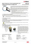
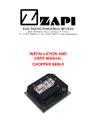
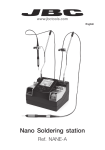
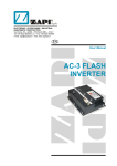
ELECTRONIC • OLEODYNAMIC • INDUSTRIAL
EQUIPMENTS CONSTRUCTION
Via Parma, 59 – 42028 – POVIGLIO (RE) – ITALY
Tel +39 0522 960050 (r.a.) – Fax +39 0522 960259
e-mail: [email protected] – web: www.zapispa.it
EN
User Manual
SMART
ANTENNA
Copyright © 1975-2005 Zapi S.p.A.
All rights reserved
The contents of this publication is a ZAPI S.p.A. property; all related authorizations are covered
by Copyright. Any partial or total reproduction is prohibited.
Under no circumstances will Zapi S.p.A. be held responsible to third parties for damage caused
by the improper use of the present publication and of the device/devices described in it.
Zapi spa reserves the right to make changes or improvements to its products at any time and
without notice.
The present publication reflects the characteristics of the product described at the moment of
distribution. The publication therefore does not reflect any changes in the characteristics of the
product as a result of updating.
is a registered trademark property of Zapi S.p.A.
NOTES LEGEND
4
U
Page - 2/24
The symbol aboard is used inside this publication to indicate an annotation or a
suggestion you should pay attention.
The symbol aboard is used inside this publication to indicate an action or a
characteristic very important as for security. Pay special attention to the
annotations pointed out with this symbol.
ADCZP0DA - SMART ANTENNA - User Manual
Contents
1
2
3
4
5
6
7
8
INTRODUCTION ...................................................................................................................5
ELECTRICAL SPECIFICATIONS .........................................................................................6
2.1
Supply voltage range ..................................................................................................6
2.2
Supply current.............................................................................................................6
2.3
Guide wire frequency and current...............................................................................6
MECHANICAL SPECIFICATION ..........................................................................................7
INSTALLING THE SMART ANTENNA .................................................................................8
4.1
Combining Smart Antennas and Eps-ac WG ...........................................................10
SMART ANTENNA CONNECTION.....................................................................................12
5.1
Connecting the Smart Antennas to the Eps-ac WG .................................................13
FUNCTIONS OF THE ANTENNA (ZAPI HAND SET DESCRIPTION) ...............................14
6.1
Communicating with the Antenna .............................................................................14
6.2
Hand Set function map .............................................................................................15
6.3
Main menu PARAMETER CHANGE list ...................................................................15
6.3.1
LINE FREQ. KHZ........................................................................................15
6.3.2
LEAD REGULATION ..................................................................................16
6.3.3
LAG REGULATION ....................................................................................16
6.3.4
ACQUISITION AREA..................................................................................16
6.3.5
ANTENNA HEIGHT MM .............................................................................17
6.4
Main menu TESTER FUNCTIONS ...........................................................................17
6.4.1
APPROACH ANGLE...................................................................................17
6.4.2
SIDE ERROR MM.......................................................................................18
6.4.3
SIDE DIST. CM...........................................................................................19
6.4.4
FIELD STRENGTH .....................................................................................20
6.4.5
ALIGNED STRENGTH ...............................................................................20
6.4.6
ANT FWD SIDE ..........................................................................................20
6.4.7
PATH ..........................................................................................................20
6.4.8
FREQUENCY .............................................................................................20
SETTING THE SMART ANTENNA .....................................................................................21
SMART ANTENNA ALARM LIST AND LED INDICATION ................................................23
ADCZP0DA - SMART ANTENNA - User Manual
Page - 3/24
APPROVAL SIGNS
COMPANY FUNCTION
INIZIALS
GRAPHIC AND LAYOUT
FF
PROJECT MANAGER
MI
TECHNICAL ELECTRONIC
MANAGER VISA
PP
SALES MANAGER VISA
PN
SIGN
Publication N°: ADCZP0DA
Edition: July 2003
Page - 4/24
ADCZP0DA - SMART ANTENNA - User Manual
1 INTRODUCTION
The Smart Antenna is the picking up device supporting the wire guidance
service.
It has embedded microprocessor, programmable digital filters and Automatic
Gain Control Logic (AGC) to convert and elaborate the picked up inductive field
into the complete information, needed to control the Automatic Guide Vehicle on
the wire.
The embedded Automatic Gain Control (AGC) compensates for the different
depth and current in the wire.
The Smart Antenna supplies an information composed of three static
components:
1) The lateral deviation (SIDE ERROR) of the antenna’s barycenter against the
wire.
2) The angle (APPROACH ANGLE) of the longitudinal axle of the antenna
against the wire.
3) The strength of the inductive field (FIELD STRENGTH).
Besides the Smart Antenna has embedded corrective network (Integral and
Derivative) and supplies a further dinamic information is:
4) The lateral deviation processed by the corrective network (Dinamic SIDE
ERROR).
There is also a further Boolean information is the presence of the inductive
electromagnetic field:
5) Field perceived (ON/OFF).
These components (from 1) to 5)) togheter with the Service Data Object form the
whole Wire Guide information that is output on the Can Bus Communication
system. All the setting operations are Zapi hand set totally assisted. No
potentiometer to be adjusted.
The Smart Antenna can be combined with Zapi Eps_ac WG controller to perform
the complete steer services (Manual and Automatic Mode) of a warehouse truck.
ADCZP0DA - SMART ANTENNA - User Manual
Page - 5/24
2 ELECTRICAL SPECIFICATIONS
2.1 Supply voltage range
Voltage input range 13Vdc – 18Vdc.
2.2 Supply current
120mAdc
2.3 Guide wire frequency and current
The Smart Antenna may be set (with the Zapi hand set) in one of the following
mode with reference at the Frequency and Current in the wire:
5.2 kHz @ 35 mA RMS
5.2 kHz @ 78 mA RMS
6.25 kHz @ 78 mA RMS
7
kHz @ 78 mA RMS
9.1 kHz @ 78 mA RMS
10 kHz @ 78 mA RMS
The tolerance on the frequency is
±20Hz
The tolerance on the wire current is ±15%
Other frequencies are possible on request.
Page - 6/24
ADCZP0DA - SMART ANTENNA - User Manual
3 MECHANICAL SPECIFICATION
Figure 3–1
ADCZP0DA - SMART ANTENNA - User Manual
Page - 7/24
4 INSTALLING THE SMART ANTENNA
The bottom edge (i.e. the lower circular surface) of each antenna must be
positioned approximately 25 to 65 mm above the embedded guide wire.
Figure 4–1
When guiding Automatic mode on the wire, the Center of the antenna (leading
the motion), will follow the wire line. That means the antennas must be mounted
on the vehicle in a longitudinal line that is the wished position of the wire under
the truck while travelling Automatic Mode (i.e. That normally means the center of
the antenna being aligned with the center line of the truck).
Figure 4–2
The Drive Unit antenna (FWD ANTENNA) may be mounted either in front or in
the back of the Stereed Wheel (see the Figure below). When the FWD antenna
is in the back of the Steered wheel (Type 1), the acquisition in the Steered Wheel
side first (FWD side) is favorite (less delay to have the vehicle aligned on the
wire); but the guide in lock-on is more difficult.
Page - 8/24
ADCZP0DA - SMART ANTENNA - User Manual
Figure 4–3
The preferred position for the installation of the Load Wheel Side Antenna (REV
ANTENNA) is from the Load Wheel Axle line towards the load edge of the Truck
(Figure 4–4 below).
Figure 4–4
When the above suggestion cannot be satisfied for mechanics ties, we can
accept the REV Antenna being mounted few centimeters (up to 10-15cm) inner
the Load Wheel Axle Line (Figure 4–5). In this case it is necessary the maximum
Steered wheel angle is larger than 90 degrees to allow the truck acquires Load
Wheel side first.
ADCZP0DA - SMART ANTENNA - User Manual
Page - 9/24
Figure 4–5
4
IMPORTANT: the iron around the antenna distorces the magnetic field: this
results in a truck angle measurement corrupted. So take care the iron frame
around the antenna has a regular geometrical shape (as a thumb rule the
antenna should be mounted under a iron flat surface: no sharp corners or iron
bands or something in an circular area of about 250mm diameter around the
antenna). This is expecially asked for the Load wheel side antenna.
Besides, the antenna must be mounted perfectly parallel to the floor (horizontal).
4.1 Combining Smart Antennas and Eps-ac WG
When the Smart Antennas are connected to an Eps-ac WG controller, the
Antennas must be oriented in the same side: that means the Forward and
Reverse antennas must be mounted so that the Antenna’s cable exits the same
side respect to an external watcher (both in left or both in the right side respect to
an external watcher facing the steered wheel).
Page - 10/24
ADCZP0DA - SMART ANTENNA - User Manual
Installation Mode #1:
In the standard ZAPI Eps-ac WG, the Installation Mode #1 below, must be
chosen when the FEEDBACK ENC reading in the Eps-ac WG increases
meanwhile the steered wheel is turning in the left side respect to an external
watcher facing the steered wheel (i.e. in Clockwise Side).
TRUCK PLANT
Load wheel
REV ANT
FWD ANT
Steered Wheel
FEEDBACK ENC increases
Load wheel
Figure 4–6
Installation Mode #2:
In the standard ZAPI Eps-ac WG, the Installation Mode #2 below, must be
chosen when the FEEDBACK ENC reading in the Eps-ac WG increases
meanwhile the steered wheel is turning in the right side respect to an external
watcher facing the steered wheel (i.e. in CounterClockwise Side).
TRUCK PLANT
Load wheel
FEEDBACK ENC increases
Steered Wheel
REV ANT
FWD ANT
Load wheel
Figure 4–7
When in closed loop the vehicle diverges from the wire, you have chosen the
wrong Installation Mode: in this case it is necessary to switch to the other one.
We rejected to use a Hand Set option to reverse the SIDE ERROR sign because
an HW intervention is more safe.
ADCZP0DA - SMART ANTENNA - User Manual
Page - 11/24
5 SMART ANTENNA CONNECTION
Figure 5–1
Each antenna has a shielded cable with 5 wires and the shield. The wires
assignement is the following:
WHITE : VDD. Positive supply voltage (13Vdc to 18Vdc)
YELLOW :
CANL line
GREEN :
CANH line
GREY :
MODE. To specify the antenna position in the Truck.
BROWN :
GND. Negative supply voltage.
SHIELD :
NC
The MODE input specifies the antenna position in the truck. MODE must be
connected to VDD for the antenna in the Steered wheel side (FWD); MODE must
be connected to GND for the antenna in the Load wheel side (REV).
The antennas will be supplied with a 5.5meters shielded cable without terminals
in the end of the cable. In such a way the final user may shorten the cable and it
may go acrossing narrow route from the antenna site to the controlling unit (e.g.
Eps-ac WG).
4
Page - 12/24
The shield is already connected to the GND inside the antenna. So the shield
must not be connected to the controller.
ADCZP0DA - SMART ANTENNA - User Manual
5.1 Connecting the Smart Antennas to the Eps-ac WG
When the antenna is connected to the Eps-ac WG the suggested connection
diagram is the following:
Figure 5–2
ADCZP0DA - SMART ANTENNA - User Manual
Page - 13/24
6 FUNCTIONS OF THE ANTENNA (ZAPI
HAND SET DESCRIPTION)
This section describes the antenna functions.
6.1 Communicating with the Antenna
When the antenna is connecting to the Eps-ac WG, it is possible to communicate
with the antenna by connecting the ZAPI hand set to the Eps-ac WG and by
entering the SET MODEL item. Then select the CONNECTED TO item and roll it
to the value 11.
Use the next item (MODEL TYPE) of the SET MODEL menu to choose which
antenna to communicate with.
Set MODEL TYPE=0
to select the FWD antenna (i.e. the antenna in the
steered wheel side).
Set MODEL TYPE=1
to select the REV antenna (i.e. the antenna in the load
wheel side).
Save and reset the console by pushing in the same time the three bottom keys of
the hand set. Now the hand set will communicate with the specified antenna and
the following function map should be selectable in the display.
When the home display of the hand set shows 0V 0A you are in connection with
the FWD antenna; When the home display of the hand set shows 1V 1A you are
in connection with the REV antenna
A number inside the triangles corresponds to the same number on the hand set
keyboard buttons shown in the figure below. The orientation of the triangle
indicates the shift direction of the button effect.
Page - 14/24
ADCZP0DA - SMART ANTENNA - User Manual
6.2 Hand Set function map
Figure 6–1
6.3 Main menu PARAMETER CHANGE list
Here is the description of the parameter change list.
6.3.1 LINE FREQ. KHZ
This is the specification of the frequency in the wire. It may assume the following
values:
- 5.2
- 6.2
to be more precise it is 6.25 KHz
- 7.0
- 9.1
- 10 .0
The current in the wire will be autoacquired (see Setting the Smart Antenna in
Topic 7).
ADCZP0DA - SMART ANTENNA - User Manual
Page - 15/24
6.3.2 LEAD REGULATION
This is the derivative contribute to an embedded PID corrective network applied
to the lateral deviation. This is used in order to avoid the oscillations (instability)
of the Wire Guidance closed loop when travelling high speed. During the set-up
procedure try different pair settings LAG and LEAD REGULATION until the truck
has the best behaviour on the wire during travelling. It is strongly suggested the
same setting for LEAD (and LAG) REGULATION on both the antennas. (see
Setting the Smart Antenna in Topic 7)
This parameter amplifies the dinamic slope of the lateral deviation of the antenna
(SIDE ERROR MM).
- Level 0 is for no lead (derivative) correction
- Level 9 is for maximum lead (derivative) correction.
Intermediate levels are for proportionally increasing lead (derivative) contribute.
6.3.3 LAG REGULATION
This is the integral contribute to an embedded PID corrective network applied to
the lateral deviation. This is used in order to avoid the oscillations (instability) of
the Wire Guidance closed loop when travelling high speed. During the set-up
procedure try different pair settings LAG and LEAD REGULATION until the truck
has the best behaviour on the wire during travelling. It is strongly suggested the
same setting for LEAD (and LAG) REGULATION on both the antennas. (see
Setting the Smart Antenna in Topic 7)
This parameter attenuates at high frequency the dinamic slope of the lateral
deviation of the antenna (SIDE ERROR MM). So it works as a low pass filter on
the LEAD REGULATION contribute.
- Level 0 is for no lag (integral) correction.
- Level 9 is for maximum low pass filtering.
Intermediate levels are for proportionally increasing lag (integral) contribute.
6.3.4 ACQUISITION AREA
This setting modifies the threshold on the field strength at which the antenna
assumes the field perceived. It is tailored on the ALIGNED STRENGTH (see
6.4.5) setting. It defines the area around the wire in which the antenna assumes
the wire perceived. .
- Level 0 is for a low sensitive antenna. (e.g. for an ALIGN STRENGTH = 65% It
assumes the field perceived when the FIELD STRENGTH reading is higher than
34%).
- Level 9 is for a high sensitive antenna. (e.g. for an ALIGN STRENGTH = 65% It
assumes the field perceived when the FIELD STRENGTH reading is higher than
10%).
NOTE: disregarding the ALIGNED STRENGTH and ACQUISITION AREA
settings, the antenna rejects to assume the field perceived when the FIELD
STRENGTH (see 6.4.4) is smaller than a minimum threshold of 10% of the
fullscale 100% field strength.
Intermediate levels are for proportionally increasing the minimum accepted field
strength.
Page - 16/24
ADCZP0DA - SMART ANTENNA - User Manual
6.3.5 ANTENNA HEIGHT MM
Specify the height of the antenna against the wire. The value to be booted must
be measured between the wire and the core of the Side Coil. The core of the
Side Coil is about 12mm upper than the bottom circular surface of the antenna
box. This setting gets the SIDE ERROR meausurement directly converted into
millimeters. It may assume the range values from 30 to 75 mm in 5mm step.
Figure 6–2
6.4 Main menu TESTER FUNCTIONS
Each TESTER function provides the measure, executed by the software, of the
specified parameter. Here is the description of the TESTER MENU list.
6.4.1 APPROACH ANGLE
It provides the angle of the antenna against the wire. The antenna axle is to be
aligned with the longitudinal axle of the truck and so the APPROACH ANGLE
corresponds to the angle bewteen the longitudinal axle of the truck and the wire.
This angle is shown in degrees with sign. The angle reading is clamped to 70
degrees. Higher angle are considered not consistent. This APPROACH ANGLE
is used during acquisition.
Figure 6–3
When the antenna is positioned as in the figure below, the APPROACH ANGLE
is positive.
ADCZP0DA - SMART ANTENNA - User Manual
Page - 17/24
ANGLE = + 30°
Figure 6–4
6.4.2 SIDE ERROR MM
It provides the lateral deviation of the barycenter of the antenna against the wire
in a narrow window of +/- 80mm around the wire. The reading is directly in
millimiters with sign provided that the ANTENNA HEIGHT MM (see 6.3.5) is
correctly adjusted. This reading is used for lock-on guide and for the detection
the truck is losing the wire path.
Figure 6–5
When the antenna is positioned as in the figure below, the SIDE ERROR MM is
positive.
Page - 18/24
ADCZP0DA - SMART ANTENNA - User Manual
SIDE ERROR = + 30mm
Figure 6–6
6.4.3 SIDE DIST. CM
It provides a coarse measurement of the distance of the barycenter of the
antenna against the wire in a wide window (0 to 20cm). This measurement
compares the FIELD STRENGTH with the ALIGNED STRENGTH to estimate the
absolute distance of the antenna against the wire. It assumes the value 0.0 when
the present field is higher equal than the ALIGNED STRENGTH (see 6.4.5). The
value increases over 0.0 when the present FIELD STRENGTH is smaller than
ALIGNED STRENGTH. It does not matter the accuracy of this reading but this
information (I mean the field strength against the ALIGNED STRENGTH) is used
in the acquisition mode to proportionally correct the steered wheel angle
according to the distance of the antenna against the wire.
Figure 6–7
ADCZP0DA - SMART ANTENNA - User Manual
Page - 19/24
6.4.4 FIELD STRENGTH
This is the real time strength field. It is a per cent of the full field range the
antenna is able to pick-up. When FIELD STRENGTH is equal higher than
ALIGNED STRENGTH, the truck is assumed being aligned on the wire in the
coarse SIDE DIST. CM reading (0.0 value).
6.4.5 ALIGNED STRENGTH
This is just a recording of the field strength the antenna expects to perceive when
the truck is aligned on the wire. As the current in the wire may be in a wide range
(from 30mA to 100mA) it is useful the Software knows the field strength
corresponding to a truck centered on the wire. The ALIGNED STRENGTH value
indirectly represents this measurement of the current in the wire. The higher is
the current, the higher is the field strength the antenna picks up. This reading is
used to equalize the ACQUISITION AREA (see 6.3.4) and the admitted field
range, disregarding of the width of the current in the wire.
ALIGNED STRENGTH is not a real time measurement; it is just the value
acquired at the installation procedure (see Topic 7 Setting The Smart Antenna).
6.4.6 ANT FWD SIDE
ON/OFF. This reading specifies the state of the MODE input (GREY wire).
ANT FWD SIDE is ON in the FWD side antenna (MODE to VDD).
ANT FWD SIDE is OFF in the REV side antenna (MODE to GND).
6.4.7 PATH
ON/OFF. This reading turns ON when the antenna picks-up the field.
The field is assumed perceived when the FIELD STRENGTH is higher than the
threshold specified with the ACQUISITION AREA setting (provided that this
threshold is higher than 10%).
6.4.8 FREQUENCY
About 300 Hz. Whatever is the frequency in the wire, it will be converted in a
fixed frequency close to 300 Hz that corresponds to the center band frequency of
the aboard filters. This conversion frequency is wished being 300 Hz ±20Hz. If it’s
outside this window it is necessary a fine tuning of the antenna at the real line
driver frequency (see step5 of the Cap. 7 “Setting the Smart Antenna”).
Page - 20/24
ADCZP0DA - SMART ANTENNA - User Manual
7 SETTING THE SMART ANTENNA
The following setting procedure is carried out with the Zapi hand set connected to
the eps_ac WG and communicating with the antenna (see 6.1).
This setting must be carried out on both the antennas separately.
Carry out the procedure for each antenna in the following sequence.
Step1- Verify the antenna in the Steered wheel side has the GREY wire
(MODE) connected to VDD (i.e. connected to an higher then 10Vdc
voltage).
Step2- Verify the antenna in the Load wheel side has the GREY wire (MODE)
connected to GND.
Step3- Set the LINE FREQ. KHZ parameter at the wire frequency.
Step4- Set the ANT. HEIGHT MM at the correct value (this is the sum between
the distance of the lower base of the antenna against the wire and the
distance between the lower antenna base and the coil center (12mm)).
Step5- Guide the truck in manual mode perfectly aligned on the wire with both
the antennas centered. Enter the FREQUENCY reading in the TESTER
menu. This must be in the window 300Hz ±20Hz. Otherwise check the
matching between the frequency in the wire and the LINE FREQ. KHZ
setting. When the FREQUENCY is few herz outside the admitted
window, perhaps your line driver is not perfectly tuned at the rated
frequency. In this case it is necessary to execute a fine tuning of the
antenna at the real line driver frequency. This operation requires the
following procedure:
a)
b)
Enter the ALARM menu.
Push in the same time the two right side keys on the hand set to
enter the hidden menu
c) Roll for the SPECIAL ADJUST item.
d) Enter in it. Roll for the FREQUENCY ACQ setting
e) Turn the FREQUENCY ACQ setting to level ON.
f) Push Twice the Enter key.
g) Verify the reading FREQUENCY in the TESTER menu is in the
window 300Hz ±20Hz.
Step6- Guide the truck in manual mode perfectly aligned on the wire with both
the antennas centered. Acquire the ALIGNED STRENGTH field. This
setting requires the following procedure:
a)
b)
c)
d)
e)
f)
g)
h)
Enter the ALARM menu.
Push in the same time the two right side keys on the hand set to
enter the hidden menu
Roll for the SPECIAL ADJUST item.
Enter in it. Roll for the STRENGTH ACQ setting
Turn the STRENGTH ACQ setting to level ON.
Push Twice the Enter key.
Verify the reading ALIGNED STRENGTH in the TESTER menu
resulted less than 100% and higher than 10%. (It is expected
close to 70% @ 78mArms in the wire; 60% @ 35mArms in the
wire).
Verify this reading is equal to the FIELD STRENGTH reading of
the TESTER menu that is the real time refreshed field
measurement. These two readings should be always very close
when the truck is aligned on the wire.
With this procedure the SW automatically records the present
ADCZP0DA - SMART ANTENNA - User Manual
Page - 21/24
field strength in the ALIGNED STRENGTH item of the TESTER
menu. With this setting the SW adapts the range of the admitted
strength field values at the different wire current in the wire.
Step7- For the LEAD and LAG REGULATION it is necessary to close the loop
with the controller (e.g. the eps_ac WG) in automatic mode on the wire.
These two settings must be adjusted to get the best set up of the truck
while travelling full speed on the wire. The LAG (and LEAD
REGULATIONs too) should be set at the same level on the two
antennas.
Page - 22/24
ADCZP0DA - SMART ANTENNA - User Manual
8 SMART ANTENNA ALARM LIST AND LED
INDICATION
Here is the smart antenna alarm list. This alarm appears on both, the hand set
display when it is connected to the antenna and on the aboard Diagnostic LED.
When the LED on the smart antenna flashes the antenna is supplied and the SW
is running.
This flashing is prevalently ON when the antenna is not perceiving the field.
This flashing is prevalently OFF when the antenna is perceiving the field.
This flashing has blinks burst when the antenna is alarmed.
LED
Figure 8–1
1) COIL MISMATCH
Three Blinks Alarm
Cause:
There is a redundancy in the elaboration of the Side Coil: it is
processed with two distinct filters, two distinct AGCs and two
distinct modulation lines in order it will be possible to detect a
failure in the processing circuits. The aim of this handling is that,
without this redundant handling, a failure of the Side Coil
processing circuit results in a null SIDE ERROR value, although
the antenna is diverging from the wire (it is dangerous). This alarm
occurs when the two processing lines give SIDE ERROR
measurements different more than 50mm.
Remedy: It is necessary to substituite the antenna.
2) COIL OPEN
Two Blinks Alarm
Cause:
This alarm occurs when the Side Coil is broken. The Side Coil
signal is pulled-up with a resistance in order it can be possible to
detect when the Side Coil is interrupted. The aim of this diagnosis
is that when the Side Coil breaks the SIDE ERROR value is null,
although the antenna is diverging from the wire (it is dangerous)..
Remedy: It is necessary to substituite the antenna.
ADCZP0DA - SMART ANTENNA - User Manual
Page - 23/24
3) EEPROM KO
One Blink Alarm
Cause:
This alarm occurs when the not volatile Eprom with the set-up
parameters is failed.
Remedy: It is necessary to substituite the antenna
Togheter with the above alarms list, there is a Watch-Dog supervisor circuit that
cut-off the CAN Bus communication when the Analog Signals of the antenna’s
coils are frozen.
Page - 24/24
ADCZP0DA - SMART ANTENNA - User Manual