1
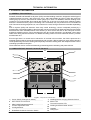
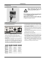
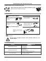
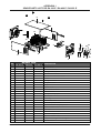
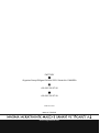
USER MANUAL RA 300 E RA 400 E RA 650 E WELDING RECTIFIER www.magmaweld.com CONTENTS SAFETY RULES ................................................................................................................................................2 1. TECHNICAL INFORMATION .........................................................................................................................6 1.1 GENERAL EXPLANATIONS ....................................................................................................................6 1.2 COMPONENTS OF RA 300 E / RA 400 E / RA 650 E .............................................................................6 1.3 DATA PLATE ............................................................................................................................................7 1.4 TECHNICAL SPECIFICATIONS ..............................................................................................................8 1.5 ACCESORRIES .......................................................................................................................................8 2. INSTALLATION ..............................................................................................................................................9 2.1 UPON RECEIPT AND CLAIMS................................................................................................................9 2.2 WORKING CONDITIONS ........................................................................................................................9 2.3 ELECTRIC PLUG CONNECTION..........................................................................................................10 2.4 CONNECTIONS FOR MMA WELDING .................................................................................................10 2.5 CONNECTIONS FOR TIG WELDING ...................................................................................................10 3. OPERATION.................................................................................................................................................11 3.1 CONNECTING TO THE MAINS .............................................................................................................11 3.2 WELDING ADJUSTMENTS....................................................................................................................11 3.2.1 Welding Adjustments .....................................................................................................................11 3.2.2 Remote Control (Optional).............................................................................................................11 4. MAINTENANCE AND TROUBLESHOOTING..............................................................................................12 4.1 MAINTENANCE .....................................................................................................................................12 4.2 TROUBLESHOOTING ...........................................................................................................................12 APPENDIX 1: SPARE PARTS LIST FOR RA 300 E / RA 400 E / RA 650 E...................................................13 APPENDIX 2: ELECTRICAL DIAGRAM FOR RA 300 E / RA 400 / RA 650 E................................................14 RA 300 E / RA 400 E / RA 650 E 1 SAFETY RULES OBEY ALL THE SAFETY RULES STATED IN THE MANUAL! IDENTIFYING SAFETY INFORMATION These symbols are being used to identify potential risks. When seen a safety symbol in the manual, it must be understood that there is an injury risk and following instructions must be read carefully to avoid potential risks. While welding, keep the third persons and especially the children away from the work area. UNDERSTANDING THE SAFETY WARNINGS Read carefully the manual and the labels and the safety warnings on the machine. Make sure that the warning labels positioned on your machine are in good order. Renew the damaged and the missing labels. Learn to operate the machine and how to make the controls properly. Operate your machine in convenient work areas. Improper modifications affect the safety of your machine negatively and shorten its lifetime. ELECTRICAL SHOCK CAN BE FATAL Installation procedure must comply with national electricity standards and other relevant regulations and ensure that installation is performed by qualified persons. Wear dry insulating gloves free of damage and body protection. Do not touch electrode with bare hand. Do not wear wet or damaged gloves and body protection. Do not touch live electrical parts. Never touch electrode while in contact with working surface, ground or another electrode which is connected to a different machine . Protect yourself from electric shock by insulating yourself from work and ground. Use non-flammable, dry insulating material if possible, or use dry rubber mats, dry wood or plywood, or other dry insulating material big enough to cover your full area of contact with the work or ground, and watch for fire. Never connect more than one electrode to the electrode holder. Turn off the machine, when not in use . Disconnect input plug or swtich off the power before working on the machine. Frequently inspect input power cord for damage or bare wiring - repair or replace cord immediately if damaged. Be sure that the machine is properly grounded. HOT PARTS CAN CAUSE SEVERE BURNS Do not touch hot parts. Allow cooling time before servicing. If needed to hold hot parts, use appropriate tool, insulating gloves and fireproof clothes. 2 RA 300 E / RA 400 E / RA 650 E SAFETY RULES BREATHING WELDING FUMES CAN BE HAZARDOUS TO YOUR HEALTH Inhaling fumes and gases over a long period of time, generated during welding is dangerous and forbidden . Irritation of the eyes, nose and throat are symptoms of inadequate ventilation. Take immediate steps to improve ventilation. Do not continue welding if symptoms persist. Install a natural or forced air ventilation system in the work area. Install an adequate ventilation system in the welding and cutting area, if needed install a system that can remove the fume and vapor accumulated in the entire work area, to prevent pollution use adequate filtration in discharge. In the event of welding in small, confined places, or welding lead, beryllium, cadmium, zinc, zinc coated or painted materials; also wear a fresh air supplied respirator in addition to the above mentioned rules . Always have a trained watchperson nearby, while working in small confined places. Avoid working in such confined places if possible. If gas cylinders are grouped in a different area, make sure that it is a well-ventilated area. When not being used, turn off the main cylinder valve and watch out for gas leakage . Shielding gasses such as argon is denser than air and when being used in confined places, it can be inhaled which is dangerous for health. Do not perform welding operations near chlorinated hydrocarbon vapors produced by degreasing or painting. ARC RAYS CAN BURN EYES AND SKIN Use adequate welding helmet with correct shade of filter (4 or 13 considering EN 379) to protect your eyes and face. Protect open parts of your body (arms, neck and ears) from arc rays by adequate protective clothing. To protect others by arc rays and hot metals, surround the working area with flame proof curtains which are higher than eye level and put up warning boards. SPARKS & FLYING METALS CAN INJURE EYES Welding, wire brushing and grinding cause sparks and flying metal. To prevent injuries wear appropriate safety glasses with side shields even under your welding helmet . MOVING PARTS CAN CAUSE INJURY Keep away from moving parts. Keep all doors, panels, and guards closed and secured. Wear shoes with metal protection over the fingers. RA 300 E / RA 400 E / RA 650 E 3 SAFETY RULES NOISE CAN DAMAGE HEARING Noise from certain industrial processes or equipments can damage hearing. Wear approved ear protection if noise level is high. WORKING IN SMALL AND CONFINED PLACES CAN BE DANGEROUS While welding and cutting in small, confined places, always have a trained watchperson nearby. Avoid working in such confined places. WELDING WIRE MAY CAUSE INJURY Do not point the torch toward any part of a human body, other persons or any type of metal when unwinding welding wire. While extracting the wire from the spool by hand, it may spring suddenly and injure you or a nearby person, protect especially your eyes and face. WELDING CAN CAUSE FIRE OR EXPLOSION Never weld near flammable material. It may cause fire or explosions. Before starting to weld, move flammables away or protect them with flame-proof covers. Do not weld on and cut closed tubes or pipes. Before welding on closed containers, open and clear them entirely. Welding operations on these parts must be performed with the utmost caution. Never weld containers or pipes containing or which have contained substances that could give rise to explosions. Welding equipments warms up so never position them on flammable surfaces. Welding sparks can cause fire. For that reason, keep extinguishing means, such as fire extinguishers, water and sand which are easy to reach. Keep security valves, regulators and other valves, used on flammable, explosive and compressed gas circuits, in good condition. MAINTENANCE MADE BY UNQUALIFIED PERSONS MAY CAUSE INJURIES Electrical devices should not be repaired by unqualified persons. Improper repairs can cause serious injuries or even death during applications. The components of the gas circuit works under pressure. The service given by unqualified persons may cause explosions and operators can be injured seriously. 4 RA 300 E / RA 400 E / RA 650 E SAFETY RULES FALLING UNIT CAN CAUSE INJURY Wrong positioned power source or other equipment may cause serious injury to persons or damage to objects. While repositioning the power source always carry by using the lifting eye. Never pull cable, hose or torch. Always carry the gas cylinders separately. Before carrying the welding and cutting equipment, disassemble all the connections between and separately carry the small ones by handgrips and the big ones by lifting eyes or by using appropriate vehicles like forklifts. Install your machine on flat platforms having maximum 10° slope that it does not fall over. Install it on well ventilated, non-confined places away from the dust, also avoiding the risk of falling caused by cables and hoses. For gas cylinders not to fall over, attach it to the mobile machine or to the wall with a chain. Ensure that operators easily reach the controls and connections on the machine. OVERUSE CAN CAUSE OVERHEATING Allow cooling period; follow rated duty cycle. Reduce current or reduce duty cycle before starting to weld again. Do not block airflow through the unit. Do not filter airflow to unit without the approval of manufacturer. ARC WELDING CAN CAUSE INTERFERENCE Electromagnetic energy arising during welding and cutting operations can interfere with sensitive electronic equipment such as microprocessors, computers, and computer-driven equipment such as robots. Be sure all equipment in the welding area is electromagnetically compatible. To reduce possible interference, keep weld cables as short as possible, close together, and down low, such as on the floor. To avoid possible EMC damages, locate welding operation as far as possible (100 meters) from any sensitive electronic equipment. Be sure this welding machine is installed and grounded according to this manual. If interference still occurs, the user must take extra measures such as moving the welding machine, using shielded cables, using line filters, or shielding the work area . PROTECTION Do not expose the welding machine to rain, protect from water drops and vapour. ENERGY EFFICIENCY Choose appropriate welding method and welding machine for your work. Choose appropriate welding current and welding voltage for the material and its thickness. If you will have a long break after welding, turn off the machine after cooler fan cooled the machine. RA 300 E / RA 400 E / RA 650 E 5 TECHNICAL INFORMATION 1. TECHNICAL INFORMATION 1.1 GENERAL EXPLANATIONS RA300E, RA400E and RA650E are thyristor (SCR) controlled welding machines, designed to weld all type of coated electrodes from 2mm, 300 model up to 5 mm, 400 & 650 models up to 6mm, while 400 model can carbon gauge up to 6mm, 650 model can carbon gauge up to 10mm. For RA650E, cellulosic welding at low currents is not recommended. Since 300 & 400 models can go as low as 20 Amps, their cellulosic welding behavior is excellent and if a proper TIG starting unit is connected, they can perform as a DC TIG welder as well. These units can be grouped as 4, 6, 8 or 9 machines in a rack, for large construction sites like shipbuilding etc. Due to thyristor (SCR) and electronic close loop control technology, current is adjusted precisely by a potentiometer, initial striking ability of the electrodes can be improved via Hot Start potentiometer and certain electrodes like basic electrodes which have tendency to short circuit and stick to the weld pool could be avoided by adjusting the Arc Force potentiometer. Also due to this technology, pre-adjusted current stays stable even during mains fluctuations or if additional welding cables are used. Electrical efficiency of these machines are 70%. Even though there is a certain level of electronics is involved in this machine, the PCB is protected in a separate cabinet inside of the machine against dust and corrosion. With its telescopic arms and big wheels it can be pulled easily across the working area especially at outdoor welding sites. Also stepless remote current controlling is possible as an option. These machines are fan cooled and thermally protected against overheating and phase failures. 1.2 COMPONENTS OF RA 300 E / RA 400 E / RA 650 E 11 7 6 8 12 9 RA 650 E 1 5 4 2 3 10 Figure 1: Components of the Machine 1 2 3 4 5 6 6 Power Switch (Changeover Switch) HOT START Current Knob ARC FORCE Adjustment Knob Current Adjustment Knob V/A Digital Meter Rutile/Basic/Cellulosic Selection Switch 7 8 9 10 11 12 Welding/Carbon Gouging Selection Switch Mains LED Thermal Protection LED Welding And Earth Cable Outlets Handles Lifting Eyes RA 300 E / RA 400 E / RA 650 E TECHNICAL INFORMATION 1.3 DATA PLATE MAGMA MEKATRONİK MAKİNE SAN. VE TİC. A.Ş. 3 Phase Transformer Rectifier EN 60974-1 EN 60974-10 Organize Sanayi Bölgesi 5.Kısım Manisa-TÜRKİYE RA 300E 3R Descending Characteristics Seri No : 10 A / 20,4 V - 300 A / 32 V 25 % 60 % X U0 66 U1 3R CL.I. H 300 A 190 A 150 A U2 32 V 28 V 22 V I1 V 380 A S1 A 30 20 20 kVA 13 kVA T 32 A 50 Hz I1 Stick Electrode Welding 100 % I2 V I1 Line Input 3 Phase Alternative Current A Direct Current 15 IP 22 10 kVA MAGMA MEKATRONİK MAKİNE SAN. VE TİC. A.Ş. EN 60974-1 EN 60974-10 Organize Sanayi Bölgesi 5.Kısım Manisa-TÜRKİYE RA 400E 3R Seri No : 20 A / 20,4 V - 400 A / 36 V 35 % 60 % X U0 U1 3R H 305 A 235 A U2 36 V 32 V 29 V I1 380 CL.I. 400 A V A S1 I1 A 38 29 25 kVA 19 kVA T 40 A 50 Hz 100 % I2 V 58 Appropriate For Dangerous Work Area S I1 A X U0 U1 U2 I1 I2 IP 21 S1 CL.I. :Duty Cycle* :Open Circuit Voltage :Line Voltage and Frequency :Rated Welding Voltage :Input Current :Rated Welding Current :Protection Class :Input Power :Insulation Class 22 14 kVA S IP 22 MAGMA MEKATRONİK MAKİNE SAN. VE TİC. A.Ş. EN 60974-1 EN 60974-10 Organize Sanayi Bölgesi 5.Kısım Manisa-TÜRKİYE RA 650E 3R Seri No : 20 A / 21 V - 650 A / 46 V 35 % 60 % X U0 68 U1 3R CL.I. H 650 A 500 A 385 A U2 46 V 40 V 35 V I1 V 380 T 80 A 50 Hz 100 % I2 V S1 A I1 A 68 52 25 kVA 19 kVA IP 22 I1 A 40 14 kVA S *Duty Cycle Temperature (°C) 1 6 min. 2 4 min. 6 min. 4 min. 6 min. 4 min. Time (min.) Duty cycle defines the percentage of welding time out of a period of 10 minutes at a given current and ambient temperature (standard is 40°C). For example, a welder with 60% duty cycle must be rested (2) for 4 minutes, after 6 minutes of continuous welding (1). RA 300 E / RA 400 E / RA 650 E 7 TECHNICAL INFORMATION 1.4 TECHNICAL SPECIFICATIONS UNIT RA 300 E RA 400 E RA 650 E V 380 380 380V Input Power (35%) kVA 20 25 45 Input Current (35%) A 30 38 68 Recommended Line Fuses A 3x32 3x40 3x80 Open Circuit Voltage VDC 66 58 68 Welding Current Range ADC 10 - 300 20 - 400 20 - 650 Rated Welding Current (35%) ADC 300 400 650 Carbon Gouging mm - 6 9 Dimensions (LxWxH) mm 950x660x640 950x660x640 950x660x640 kg 155 173.5 208 IP22 IP22 IP22 2-4 2-5 2-6 RA 300 E RA 400 E RA 650 E K301000405 - - Electrode Holder and Cable (70mm2- 5m) K301000405 - Earth Clamp and Cable (35mm - 5m) K301100403 K301100403 K301000605 - Earth Clamp and Cable (70mm - 5m) - - K301100603 Remote Control Box With 10m Cable K301400210 K301400210 K301400310 Remote Control Box With 20m Cable K301400220 K301400220 K301400320 Remote Control Box With 50m Cable K301400250 K301400250 K301400350 TECHNICAL SPECIFICATIONS Line Voltage (3 Phases 50 Hz) Weight Protection Class Electrode Diameter mm 1.5 ACCESSORIES STANDARD ACCESSORIES Electrode Holder and Cable (35mm2- 5m) 2 2 OPTIONAL ACCESSORIES 8 RA 300 E / RA 400 E / RA 650 E INSTALLATION 2. INSTALLATION 2.1 UPON RECEIPT AND CLAIMS Be sure that you have received all the items that you have ordered. In case of any item is missing or damaged, contact your supplier immediately. In the event of damaged or missing delivery, draw up a record, take a photo of the damage and report it to the shipping agency and MAGMA MEKATRONIK with the photocopy of shipping bill. Standard pallet contains: ú Power Source ú Electrode Holder Cable ú Earth Clamp Cable ú User Manual E-mail: [email protected] Fax: +90 236 226 27 28 2.2 INSTALLATION AND WORKING RECOMMENDATIONS • Use lifting eyes or fork-lift to carry the machine. Transport and place the device on a firm and level ground so that it may not fall over. The maximum permissible angle of inclination for transport and assembly is 10°. • For a better performance, keep the machine at least 30 cm away from the surrounding objects. Beware of excessive heat, dust and humidity around the machine. Try not to operate the machine under direct sunlight. Machines should be operated on lower capacities when ambient air temperature exceeds 40ºC. • Avoid welding at outdoors where it is windy and rainy, if this is a must, protect the welding area with curtains, mobile screens or tents. RA 300 E / RA 400 E / RA 650 E • Ensure that operators can easily reach the machine controls and connections. • Use suitable welding fume extraction systems. Use breathing apparatus if there is a risk of inhaling in confined places. • Respect the duty cycles given at the data plate. Exceeding the duty cycles frequently can damage the machine and this would void the warranty. • Do not use stronger fuses than those stated on the data plate. • Ensure that the earth clamp is tightly connected as close as possible to the welding location. Do not let welding current flow through any media other than welding cables; e.g. over the machine itself, gas tubes, chains, ball bearings, etc. 9 INSTALLATION 2.3 ELECTRIC PLUG CONNECTION Since mains connection sockets may vary from factory to factory, an appropriate plug must be installed to the built-in mains cable of the machine by qualified electricians. Please observe that the earth cable is in yellow/green colour and labeled as . After installing the electric plug, DO NOT INSERT IT INTO THE SOCKETAT THIS STAGE. Figure 2: Electric Plug Connection 2.4 MMA WELDING CONNECTIONS According to the polarity of the electrode to be used, insert welding cables into the appropriate outlet (10) and tighten them by turning clock-wise. Connect the earth clamp tightly to the workpiece as close as possible to the welding area. Figure 3: MMA Welding Connections 2.5 TIG WELDING CONNECTIONS TIG torch with a valve should be used. Connect the TIG torch power cable to the negative outlet and the earth cable to the positive outlet (10) of the machine. Install the Argon gas regulator onto the Argon gas cylinder. Connect the gas hose of the torch to the gas regulator. Figure 5: Connecting Gas Cylinder Figure 4: TIG Welding Connections 10 RA 300 E / RA 400 E / RA 650 E OPERATION 3. OPERATION 3.1 CONNECTING TO THE MAINS While inserting the plug into the socket, pay attention that main switch is positioned to “OFF” “0”. Before plugging your machine to the electrical line check carefully the2:3Electric phasePlug withConnection a voltmeter and then Figure insert the plug into the socket. SWITCH ON the machine via power switch (1). Observe the fan noise and illumination of the mains LED (8) and V/A digital meters (5). Figure 6: Mains Connection 3.2 WELDING ADJUSTMENTS For better ignition turn the HOT START knob (2) 3.2.1 Welding Adjustments 6 7 5 4 RA 650 E 3.2.2 Remote Control (Optional) Figure 7: Control Panel Select via the selection switch (6) the type of the electrode (rutile/basic/cellulosic) to be used. For carbon gauging, toggle the selection switch (7) downwards. Welding current is adjusted via current adjustment knob (4) and the adjusted current value can be observed from the ammeter (5). Below table can be used as a rough reference for mild steel electrodes. For exact parameters, please refer to the electrode manufacturer's recommendations. Diameter Rutile Basic Cellulosic 2.0 40-60 A -- -- 2.5 60-90 A 60-90 A 60-100 A 3.25 100-140 A 100-130 A 70-130 A 4.0 140-180 A 140-180 A 120-170 A 5.0 200-240 A 200-250 A 160-200 A 6.0 260-320 A -- -- RA 300 E / RA 400 E / RA 650 E clock-wise. If the adjustment is not correct, arc can burn through the workpiece ARC FORCE is useful for electrodes which have tendency to stick into the weld pool during welding. Turning the knob (3) clock-wise will decrease the tendency to stick. Start welding and observe welding current (A) and voltage (V) by V/A meters (5). It is possible to connect a remote control box via long control cable as long as it is necessary. In this case, appropriate control socket must be installed onto the front panel by a certified Magma Service. When the remote control connector is connected to the machine, ampere adjustment knob on the machine is disabled automatically and current adjustment is made by the remote control. 11 MAINTENANCE AND TROUBLESHOOTING 4. MAINTENANCE AND TROUBLESHOOTING Before removing any screw on the machine for maintenance, power supply must be disconnected from the electric lines and 10 seconds should be allowed for capacitor discharging. 4.1 MAINTENANCE ONCE IN EVERY 3 MONTHS Clean the labels on the machine, replace the worn out labels. Repair or replace the worn out welding cables. Clean and tighten weld the terminals. Check the isolation of the electrode holder, earth clamp and their cables. ONCE IN EVERY 6 MONTHS Open the covers of the machine and clean with dry air. OR NOTE: The above recommended maintenance periods are indicative, these may vary according to the work shop conditions. DO NOT PLUG THE MAINS ELECTRIC CABLE BEFORE CLOSING ALL THE CABINET PANELS. 4.2 TROUBLESHOOTING TROUBLE Machine does not work. Welding current is low. Fan is out of order. 12 [REMEDY] REASON Phase failure No neutral line Fuse blown out Phase failure Diode breakdown A primary or secondary coil burn down Fan supply voltage phase failure Fan motor break down RA 300 E / RA 400 E / RA 650 E APPENDIX 1 SPARE PARTS LIST FOR RA 300 E / RA 400 E / RA 650 E 9 9 7 12 1 13 5 4 18 19 2 11 17 20 6 9 8 16 3 NO MATERIAL CODE RA 300 E RA 400 E RA 650 E DESIGNATION 1 A410500002 A410500002 A410500002 Rheostat 250W 2 A410801003 A410801003 A410801001 Carbon Potentiometer 3 A377900106 A377900106 A377900106 Welding Socket (T) 35-70 4 K405000068 K405000068 K405000068 Electronic Board - E101A 5 K405000016 K405000016 K405000016 Ammeter-Voltmeter Board - E901A 6 A430902001 A430902002 A430902003 Rectifier 7 A250200002 A250200002 A250200002 Cooling Fan SF-350 8 A308033102 A308033102 A308034102 Changeover Switch 9 K100200003 K100200003 K100200003 Body 10 K304500012 K304500016 K304500024 Impedance Coil 11 A225222012 A225222012 A225222012 Plastic Wheel 300x50x20 12 K304000024 K304000016 K304000032 Main Transformer 13 K302200004 K302200016 K302200024 Primary-Secondary Spool 14 A229500001 A229500001 A229500001 Knob - Small 15 A229500002 A229500002 A229500002 Knob - Big 16 A410801004 A410801004 A410801004 Potentiometer - 10K 17 A310310002 A310310002 A310310002 Mains LED (N733)-220VAC 18 A310310004 A310310004 A310310004 Thermal Protection LED (N733)-24VAC 19 A310100006 A310100006 A310100006 Switch 2 Position 1 Pole 20 A490400001 A490400001 A490400001 EMC Filter A300190001 A300190001 A300190001 Glass Fuse Socket 20x5mm A300102005 A300102005 A300102005 Glass Fuse Delayed 1 A A420000003 A420000003 A420000003 Capacitor - 100 NF / 250V A314800102 A314800102 A314800102 Temperature Limiting Switch 125 Degrees A830900004 A830900008 A830900016 Hall Effect Sensor RA 300 E / RA 400 E / RA 650 E 15 14 13 APPENDIX 2 ELECTRICAL DIAGRAM FOR RA 300 E / RA 400 E / RA 650E 14 A OFF For Rutile and Basic, On For Cellulosic Electrode B OFF For Carbon Electrode P1 Current Regulator P2 Arc Force P3 Hot Start RA 300 E / RA 400 E / RA 650 E FACTORY Organize Sanayi Bölgesi 5.Kısım 5503. Sokak No:1 MANİSA +90 236 226 27 00 +90 236 226 27 28 OWM 02.07.2011 Made in TÜRKİYE www.magmaweld.com