1
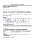
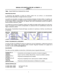
MONOTIG 160İP DC INVERTER TIG WELDING MACHINE CONTENTS SAFETY RULES.................................................................................................................................................2 1. TECHNICAL INFORMATION .........................................................................................................................6 1.1 GENERAL EXPLANATIONS ....................................................................................................................6 1.2 COMPONENTS OF MONOTIG 160iP.......................................................................................................6 1.3 DATA PLATE.............................................................................................................................................7 1.4 TECHNICAL SPECIFICATIONS...............................................................................................................7 1.5 ACCESSORRIES .....................................................................................................................................8 2. INSTALLATION...............................................................................................................................................9 2.1 UPON RECEIPT AND CLAIMS................................................................................................................9 2.2 INSTALLATION AND WORKING RECOMMENDATIONS .......................................................................9 2.3 CONNECTIONS FOR TIG WELDING......................................................................................................9 2.3.1 Mains Connection and Switching ON..............................................................................................9 2.3.2 Gas Connections.............................................................................................................................9 2.3.3 Torch Cooling System (Optional)...................................................................................................10 2.3.4 Preparing the Torch .......................................................................................................................10 2.3.5 Torch Connections.........................................................................................................................10 2.3.6 Earth Clamp Connections..............................................................................................................10 2.3.7 Changing the Tungsten Electrode .................................................................................................10 2.4 CONNECTIONS FOR MMA WELDING..................................................................................................11 3. OPERATION.................................................................................................................................................12 3.1 CONTROL PANEL..................................................................................................................................12 3.2 TIG CYCLE.............................................................................................................................................13 3.3 MENU STRUCTURE..............................................................................................................................13 3.3.1 TIG Welding Process.....................................................................................................................14 3.3.2 Usage of the TIG Welding Modes .................................................................................................14 3.3.3 MMA Welding Process ..................................................................................................................14 3.3.4 Error Message...............................................................................................................................14 4. MAINTENANCE AND TROUBLESHOOTING..............................................................................................15 4.1 PERIODIC MAINTENANCE.............................................................................................................15 4.2 NONPERIODIC MAINTENANCE.....................................................................................................15 4.3 TROUBLESHOOTING .....................................................................................................................15 APPENDIX 1: SPARE PARTS..........................................................................................................................16 APPENDIX 2: ELECTRICAL DIAGRAM...........................................................................................................17 MONOTIG 160ip 1 SAFETY RULES OBEY ALL THE SAFETY RULES STATED IN THE MANUAL! IDENTIFYING SAFETY INFORMATION These symbols are being used to identify potential risks. When seen a safety symbol in the manual, it must be understood that there is an injury risk and following instructions must be read carefully to avoid potential risks. While welding, keep the third persons and especially the children away from the work area. UNDERSTANDING THE SAFETY WARNINGS Read carefully the manual and the labels and the safety warnings on the machine. Make sure that the warning labels positioned on your machine are in good order. Renew the damaged and the missing labels. Learn to operate the machine and how to make the controls properly. Operate your machine in convenient work areas. Improper modifications affect the safety of your machine negatively and shorten its lifetime. ELECTRICAL SHOCK CAN BE FATAL Installation procedure must comply with national electricity standards and other relevant regulations and ensure that installation is performed by qualified persons. Wear dry insulating gloves free of damage and body protection. Do not touch electrode with bare hand. Do not wear wet or damaged gloves and body protection. Do not touch live electrical parts. Never touch electrode while in contact with working surface, ground or another electrode which is connected to a different machine . Protect yourself from electric shock by insulating yourself from work and ground. Use non-flammable, dry insulating material if possible, or use dry rubber mats, dry wood or plywood, or other dry insulating material big enough to cover your full area of contact with the work or ground, and watch for fire. Never connect more than one electrode to the electrode holder. Turn off the machine, when not in use . Disconnect input plug or swtich off the power before working on the machine. Frequently inspect input power cord for damage or bare wiring - repair or replace cord immediately if damaged. Be sure that the machine is properly grounded. HOT PARTS CAN CAUSE SEVERE BURNS Do not touch hot parts. Allow cooling time before servicing. If needed to hold hot parts, use appropriate tool, insulating gloves and fireproof clothes. 2 MONOTIG 160ip SAFETY RULES BREATHING WELDING FUMES CAN BE HAZARDOUS TO YOUR HEALTH Inhaling fumes and gases over a long period of time, generated during welding is dangerous and forbidden . Irritation of the eyes, nose and throat are symptoms of inadequate ventilation. Take immediate steps to improve ventilation. Do not continue welding if symptoms persist. Install a natural or forced air ventilation system in the work area. Install an adequate ventilation system in the welding and cutting area, if needed install a system that can remove the fume and vapor accumulated in the entire work area, to prevent pollution use adequate filtration in discharge. In the event of welding in small, confined places, or welding lead, beryllium, cadmium, zinc, zinc coated or painted materials; also wear a fresh air supplied respirator in addition to the above mentioned rules . Always have a trained watchperson nearby, while working in small confined places. Avoid working in such confined places if possible. If gas cylinders are grouped in a different area, make sure that it is a well-ventilated area. When not being used, turn off the main cylinder valve and watch out for gas leakage . Shielding gasses such as argon is denser than air and when being used in confined places, it can be inhaled which is dangerous for health. Do not perform welding operations near chlorinated hydrocarbon vapors produced by degreasing or painting. ARC RAYS CAN BURN EYES AND SKIN Use adequate welding helmet with correct shade of filter (4 or 13 considering EN 379) to protect your eyes and face. Protect open parts of your body (arms, neck and ears) from arc rays by adequate protective clothing. To protect others by arc rays and hot metals, surround the working area with flame proof curtains which are higher than eye level and put up warning boards. SPARKS & FLYING METALS CAN INJURE EYES Welding, wire brushing and grinding cause sparks and flying metal. To prevent injuries wear appropriate safety glasses with side shields even under your welding helmet . MOVING PARTS CAN CAUSE INJURY Keep away from moving parts. Keep all doors, panels, and guards closed and secured. Wear shoes with metal protection over the fingers. MONOTIG 160ip 3 SAFETY RULES NOISE CAN DAMAGE HEARING Noise from certain industrial processes or equipments can damage hearing. Wear approved ear protection if noise level is high. WORKING IN SMALL AND CONFINED PLACES CAN BE DANGEROUS While welding and cutting in small, confined places, always have a trained watchperson nearby. Avoid working in such confined places. WELDING WIRE MAY CAUSE INJURY Do not point the torch toward any part of a human body, other persons or any type of metal when unwinding welding wire. While extracting the wire from the spool by hand, it may spring suddenly and injure you or a nearby person, protect especially your eyes and face. WELDING CAN CAUSE FIRE OR EXPLOSION Never weld near flammable material. It may cause fire or explosions. Before starting to weld, move flammables away or protect them with flame-proof covers. Do not weld on and cut closed tubes or pipes. Before welding on closed containers, open and clear them entirely. Welding operations on these parts must be performed with the utmost caution. Never weld containers or pipes containing or which have contained substances that could give rise to explosions. Welding equipments warms up so never position them on flammable surfaces. Welding sparks can cause fire. For that reason, keep extinguishing means, such as fire extinguishers, water and sand which are easy to reach. Keep security valves, regulators and other valves, used on flammable, explosive and compressed gas circuits, in good condition. MAINTENANCE MADE BY UNQUALIFIED PERSONS MAY CAUSE INJURIES Electrical devices should not be repaired by unqualified persons. Improper repairs can cause serious injuries or even death during applications. The components of the gas circuit works under pressure. The service given by unqualified persons may cause explosions and operators can be injured seriously. 4 MONOTIG 160ip SAFETY RULES FALLING UNIT CAN CAUSE INJURY Wrong positioned power source or other equipment may cause serious injury to persons or damage to objects. While repositioning the power source always carry by using the lifting eye. Never pull cable, hose or torch. Always carry the gas cylinders separately. Before carrying the welding and cutting equipment, disassemble all the connections between and separately carry the small ones by handgrips and the big ones by lifting eyes or by using appropriate vehicles like forklifts. Install your machine on flat platforms having maximum 10° slope that it does not fall over. Install it on well ventilated, non-confined places away from the dust, also avoiding the risk of falling caused by cables and hoses. For gas cylinders not to fall over, attach it to the mobile machine or to the wall with a chain. Ensure that operators easily reach the controls and connections on the machine. OVERUSE CAN CAUSE OVERHEATING Allow cooling period; follow rated duty cycle. Reduce current or reduce duty cycle before starting to weld again. Do not block airflow through the unit. Do not filter airflow to unit without the approval of manufacturer. ARC WELDING CAN CAUSE INTERFERENCE Electromagnetic energy arising during welding and cutting operations can interfere with sensitive electronic equipment such as microprocessors, computers, and computer-driven equipment such as robots. Be sure all equipment in the welding area is electromagnetically compatible. To reduce possible interference, keep weld cables as short as possible, close together, and down low, such as on the floor. To avoid possible EMC damages, locate welding operation as far as possible (100 meters) from any sensitive electronic equipment. Be sure this welding machine is installed and grounded according to this manual. If interference still occurs, the user must take extra measures such as moving the welding machine, using shielded cables, using line filters, or shielding the work area . PROTECTION Do not expose the welding machine to rain, protect from water drops and vapour. ENERGY EFFICIENCY Choose appropriate welding method and welding machine for your work. Choose appropriate welding current and welding voltage for the material and its thickness. If you will have a long break after welding, turn off the machine after cooler fan cooled the machine. MONOTIG 160ip 5 TECHNICAL INFORMATION 1. TECHNICAL INFORMATION 1.1 GENERAL EXPLANATIONS Monotig 160ip is an inverter type portable, mono-phase Pulsed DC TIG/MMA welding machine designed for TIG welding of all kinds of thin metal sheets except aluminum & for MMA welding of all kinds of stick electrodes up to 4 mm. Enhanced professional TIG controls such as, HF start, Touch-Lift, pre-gas, up-slope, pulse, down-slope, postgas & crater filling are present. Up to 10 complete jobs can be stored in the memory and run when it is necessary. Current, time and program settings can easily be monitored by digital displays. Monotig 160ip proved well that it can work between 160 to 240 V 50/60 Hz line voltages. Therefore this machine is quite immune to mains voltage fluctuations and perfectly welds with generator-sets. Monotig160ip can also be used with long welding cables up to 25 mt. The machine is fan cooled and thermally protected against over heating. 1.2 COMPONENTS OF MONOTIG 160iP 10 8 9 3 5 6 2 1 4 7 Figure 1: Monotig 160ip 1 2 3 4 5 6 Line Cable Inlet Power Switch Gas Inlet Gas Outlet Earth Cable and Welding Cable Socket (-) 6 7 8 9 10 Earth Cable and Welding Cable Socket (+) Torch Control Connections Control Panel Multifunctional Adjustment Knob Thermic / Error LED MONOTIG 160ip TECHNICAL INFORMATION 1.3 DATA PLATE Single Phase Static Frequency Converter Transformer Rectifier MONOTIG 160ip TIG Welding 30A / 11.2V ~ 160A / 16.4V 50 160A 16.4V 22A 5kVA 22A Manual Metal Arc Welding 145A 110A 15.8V 14.4V 15.3A 13.2A 3.5kVA 3kVA 15.5A Direct Current Descending Characteristics Line Input-1 Phase Alternating Current 30A / 21.2V ~ 160A / 26.4V Appropriate To Operate In Dangerous Work Area X U0 U1 U2 I1 I2 IP23S S1 :Duty Cycle* :Open Circuit Voltage :Line Voltage and Frequency :Rated Welding Voltage :Input Current :Rated Welding Current :Protection Class :Input Power *Duty Cycle Temperature (°C) 1 6 min. 2 4 min. 6 min. 4 min. 6 min. 4 min. Time (min.) Duty cycle defines the percentage of welding time out of a period of 10 minutes at a given current and ambient temperature (standard is 40°C). For example, a welder with 60% duty cycle must be rested (2) for 4 minutes, after 6 minutes of continuous welding (1). 1.4 TECHNICAL SPECIFICATIONS TECHNICAL SPECIFICATIONS Line Voltage (1 phase) Input Power - TIG (50%) Input Power - MMA (25%) Input Current - TIG (50%) Input Current - MMA (25%) Power Factor Open Circuit Voltage Welding Current Range Rated Welding Current - TIG (50%) Rated Welding Current - MMA (25%) Fuse Protection Class (EN 60529) Cooling Method Dimensions (LxWxH) Weight Standards and Approvals MONOTIG 160ip UNIT V kVA kVA A A VDC ADC ADC ADC A mm kg VALUE 230 5 7,2 22 31,5 0,97 75 30 - 160 160 150 32 - Delayed IP23S Air 515x160x312 10 CE, EN60974-1, EN60974-10 7 TECHNICAL INFORMATION 1.5 ACCESORRIES PIECE PRODUCT CODE Electrode Holder and Cable (16mm² - 3m) 1 K301000203 Earth Clamp and Cable (16mm² - 3m) 1 K301101204 TIG Torch Plug - CX79 1 A377900022 PIECE PRODUCT CODE Torch Abitig 200 (200A 35% DC - 4m) 1 S510031901 Torch Sintig 18W-4 (320A 100% DC - 4m) 1 S510031211 Torch Sintig 18W-4 (320A 100% DC - 8m) Gas Pressure Regulator (Ar-CO2) 1 1 S510031212 S520001002 Water Cooling Unit (CS 200) 1 K307000010 STANDARD ACCESORRIES OPTIONAL ACCESORRIES 8 MONOTIG 160ip INSTALLATION 2. INSTALLATION 2.1 UPON RECEIPT AND CLAIMS Be sure that you have received all the items that you have ordered. In case of any item is missing or damaged, contact your supplier immediately. In the event of damaged or missing delivery, draw up a record, take a photo of the damage and report it to the shipping agency and MAGMA MEKATRONIK with the photocopy of shipping bill. E-mail: [email protected] Fax: +90 236 226 27 28 Standard box contains: ú Power Source ú Electrode Holder Cable ú Earth Clamp Cable ú TIG Torch Plug ú Transportation Belt ú User Manual 2.2 INSTALLATION AND WORKING RECOMMENDATIONS DO NOT USE THE MACHINE WITH LONG MAINS CABLES AT CONSTRUCTION SITES! Mains cables are under 220V/50 Hz and these cables are not suitable to be used in harsh environments, they can easily wear and tear which may lead to electric leakage to the metals where welders may be working on. ELECTRIK SHOCK CAN KILL or cause people to FALL DOWN from elevated working areas . I t is ALWAYS recommended to use longer WELDING CABLES instead of MAINS CABLES for safety reasons. For a better performance, keep the machine at least 20 cm away from the surrounding objects. Beware of excessive heat, dust and humidity around the machine. Try not to operate the machine under direct sunlight. Machines should be operated on lower capacities when ambient air temperature exceeds 40ºC. Avoid welding at outdoors where it is windy and rainy, if this is a must, protect the welding area with curtains, mobile screens or tents. Use suitable welding fume extraction systems. Use breathing apparatus if there is a risk of inhaling in confined places. Respect the duty cycles given at the data plate. Exceeding the duty cycles frequently can damage the machine and this would void the warranty. Do not use stronger fuses than those stated on the data plate. Ensure that the earth clamp is tightly connected as close as possible to the welding location. Do not let welding current flow through any media other than welding cables; e.g. over the machine itself, gas tubes, chains, ball bearings, etc. Secure the gas cylinder to a wall by a chain. 2.3 CONNECTIONS FOR TIG WELDING 2.3.1 Mains Connection and Switching ON Before plugging your machine to the electrical line, check the line voltage [230 VAC]. Switch the machine to the position “OFF” “0” and insert the plug into the socket. SWITCH ON the machine via power switch (2). Observe that the switch itself and the led displays in the front panel lits, also you should hear the sound of the cooler fan. 2.3.2 Gas Connections Secure the gas cylinder (11) to a wall by a chain. To operate safely and get best results, use approved regulators. Open the gas cylinder valve (13) few times in order to blow out any possible dirt or particles. Connect the gas regulator to the cylinder, make sure that the threading of the gas outlet of the cylinder and the nut of the regulator match. 13 12 15 11 14 Figure 3: Gas Cylinder - Regulator - Hose Connections Figure 2: Gas and Mains Connections MONOTIG 160ip 9 INSTALLATION Connect one end of gas hose (14) to the gas 2.3.6 Earth Clamp Connections regulator (12) and connect the other end to the gas supply inlet (3). Open the gas cylinder valve (13). Connect the earth cable plug (23) to the positive Set the gas quantity with the pressure adjustment To increase the quality of the welding, connect the valve(15). Make sure that there are no gas leakages from any welding socket (6) tightly. earth clamp (24) tightly to the work-piece as close as possible to the welding area. connection. Diameter of Electrode (mm) Diameter of Nozzle (mm) Welding Current (ADC) Gas Debit (lt/dak) 1.0 1.6 6.3 9.5 15 - 70 30 - 150 6-8 6-8 2.3.3 Torch Cooling System (Optional) CS200 water cooling unit is an optional accessory for cooling the water cooled torches in demanding applications and it can be ordered with the code K307000010. 5 2.3.4 Preparing the Torch Connections TIG torch connection via CX79 TIG torch adaptor : 7 4 6 Thread the nut (16) of the torch through the plastic body (17) and screw to the torch plug (18) tightly. Then place the torch plug (18) into the plastic body (17). Thread the L shape gas hose adapter (19) through the hole on plastic body and screw it to the socket (18) tightly. Connect the gas hose (20) to the elbow union (19) with the clamp tightly. Install the connector pins (22) to the control cables (21) of the torch. 16 17 23 24 Figure 5: TIG Welding Connections 18 2.3.7 Changing the Tungsten Electrode 26 19 27 20 28 29 30 21 22 Figure 6: Changing the Tungsten Electrode Figure 4: Mounting the Torch Plug and the Torch 2.3.5 Torch Connections Connect the TIG torch plug that you've prepared to 10 the negative welding socket (5) tightly. Screw the gas hose of the torch to the gas outlet (4). Insert the connector pins (17) to the torch control connections (7). In case of using water cooling unit, connect the water hoses of the water-cooled torch to the water cooling unit. Unscrew the clamping cap (27). Remove the existing tungsten electrode (26) from the collet (28) and insert the new electrode in. Insert the collet (28) into the torch. Screw the clamping cap (27) tightly. The ceramic gas nozzle (30) and the tungsten electrode (26) diameters should be selected according to the working current and the shape of the work-piece. Therefore the collet (28), the collet body (29) must be matched with the diameter of the tungsten electrode (26). MONOTIG 160ip INSTALLATION 2.4 CONNECTIONS FOR MMA WELDING Switch ON the machine by following the steps 2.3.1. According to the polarity of the electrode to be used, insert the electrode holder cable (20) and the earth clamp cable (18) plugs into their appropriate sockets (5-6) and tighten them by turning clock-wise. Connect the earth clamp (24) tightly to the workpiece as close as possible to the welding area. Adjust the desired current and the machine is ready to weld. Below table is given as a reference for current 5 adjustment of mild steel electrodes, please refer to the electrode manufacturer's recommendations. Diameter Rutile Basic Cellulosic 2.0 40-60 A -- -- 2.5 60-90 A 60-90 A 60-100 A 3.25 100-140 A 100-130 A 70-130 A 4.0 140-180 A 140-180 A 120-170 A 6 20 24 18 Figure 5: MMA Welding Connections MONOTIG 160ip 11 OPERATION 3. OPERATION 3.1 CONTROL PANEL 26 19 20 2 21 18 Frequency 24 22 17 25 16 6 4 23 7 8 10 11 12 15 14 1 5 9 3 13 Monotig 160ip LED [14] lights when Flat DC TIG is selected and LED [15] lights when Pulse DC TIG is selected. [1] Multifunctional Knob is used for selecting and adjusting welding parameters. To select a parameter, press the button and observe that the corresponding LED lights. Clockwise and counter clockwise turning of the knob, increases and decreases the value respectively. To store the value, press the button. When Pulse DC TIG is selected, its LED [15] lights. [2] Multifunctional Display displays the value of the welding parameter which is selected by multifunctional knob. Plus it displays the welding current value during welding. [17] Starting Current LED is selected by pushing multifunctional knob. While LED is on, the desired value is adjusted by turning the multifunctional knob. [3] Program Selection Button is for selecting the desired program. [4] Program Display displays the number of the selected program. [5] Welding Mode Selection Button is for selecting MMA, HF Start TIG, and Touch-Lift TIG modes. When MMA mode is selected, its LED [6] lights. When Touch-Lift TIG mode is selected, its LED [7] lights. In this mode, arc starts after touching the tungsten electrode to the work-piece and lifting the electrode. [16] Pre-Gas Flow Time LED is selected by pushing multifunctional knob. While LED is on, the desired value is adjusted by turning the multifunctional knob. [18] Up-Slope Time LED is selected by pushing multifunctional knob. While LED is on, the desired value is adjusted by turning the multifunctional knob. [19] Main Current LED is selected by pushing multifunctional knob. While LED is on, the desired value is adjusted by turning the multifunctional knob. [20] Base Current LED is selected by pushing multifunctional knob. While LED is on, the desired value is adjusted by turning the multifunctional knob. [21] Pulse Frequency Adjustment LED is selected by pushing multifunctional knob. While LED is on, the desired value is adjusted by turning the multifunctional knob. When HF Start TIG mode is selected, its LED [8] lights. In this mode, arc starts via ignition through the gas without any torch touching to the work-piece. [22] Spot Welding LED lights while the torch trigger is pushed in spot welding mode. [9] 2-Stroke / 4-Stroke / Spot Welding Selection Button is for selecting 2-Stroke, 2-Stroke, and Spot Welding modes. [23] Down-Slope Time LED is selected by pushing multifunctional knob. While LED is on, the desired value is adjusted by turning the multifunctional knob. When 2-Stroke TIG is selected, its LED [10] lights. [24] Final Current LED is selected by pushing multifunctional knob. While LED is on, the desired value is adjusted by turning the multifunctional knob. When 4-Stroke TIG is selected, its LED [11] lights. When Spot Welding is selected, its LED [12] lights. Button [13] is for selecting Flat DC TIG / Pulse DC TIG. 12 MONOTIG 160ip OPERATION [25] Post Gas-Flow Time LED is selected by pushing multifunctional knob. While LED is on, the desired value is adjusted by turning the multifunctional knob. i According to the modes, active and inactive functions are shown in the table below. [26] Thermal Error LED lights when machine is overheated. 3.2 TIG CYCLE **Spot Welding Time *Pulse Frequency Start Current Current Up-slope Main Current Gas Pre-Flow Main Current ***Base Current Current Down-slope Final Current Gas Post-Flow * Only in TIG with PULSE ** Only in Spot mode *** In all TIG modes except 2-Stroke DC TIG 3.3 MENU STRUCTURE RANGE MMA Welding 2-Stroke TIG 4-Stroke TIG Spot TIG FACTORY SETTING LED 0.1 - 10 sec 1 sec 16 P P P P 30 - 160 A 30 A 17 P P P P 0.1 - 10 sec 1 sec 18 P P P P Main Current 30 - 160 A 80 A 19 P P P P Base Current 30 - 160 A 40 A 20 P P P P 0.1 - 2000 Hz 15 Hz 21 P P P 0.1 - 10 sec 1 sec 23 P P P P Final Current 30 - 160 A 30 A 24 P P P P Post-Gas Flow Time 0 - 23 sec 2 sec 25 P P P P PARAMETER Pre-Gas Flow Time Start Current Up-slope Time Frequency Down-slope Time MONOTIG 160ip DC Pulse DC Pulse DC Pulse P P P 13 OPERATION 3.3.1 TIG Welding Process Beware of electric shock! In HF Start TIG mode, a high ignition voltage is present at the torch. Never touch the tungsten electrode or parts conducting welding current when the device is switched on. between this reached welding current and the base current. If the trigger will be pushed and released more than 1 second, current decreases according to down-ramp adjustment, reaches to the final current, after post gas, welding ends. Base current is generally used for repairing and In the first use, all parameters of all programs are in factory settings which are shown in the table. cooling during welding and crater filling at the finishing of the welding beads. Either during DC or during Pulsed DC welding if the trigger is pushed and released less than 1 second , DC base current will be on. If the trigger will be pushed less than 1 second, welder will go back to the existing welding mode and parameters, but if the trigger will be pushed and released more than 1 second, welding will be finished by following the down-ramp, final current and post-gas. Spot TIG Welding Push the program selection button [3] for selecting When the torch trigger is pushed, main current a previously adjusted program or changing its parameters. starts immediately and goes on as long as the torch trigger is kept pushed. Push the welding mode selection button [5] for Welding goes on during spot welding time. After 10 Jobs (programs) including complete parameter settings can be stored and run for repeated jobs. i selecting Touch-Lift TIG or HF start TIG. Push the 2-Stroke / 4-Stroke / Spot Welding Selection Button [9] for selecting the appropriate mode for the work. spot welding time is over, current stops immediately. Flat DC / Pulse DC For using welding modes (2-stroke, 4-stroke, Spot button [13] for selecting Flat DC TIG or Pulse DC TIG. Welding) in Flat DC mode, select Flat DC mode by button [13], its LED [14] will be on. In this mode, only main current [19] is used and it is simply adjusted by the multifunctional knob [1]. Push the multifunctional knob [1] for selecting the For using welding modes (2-stroke, 4-stroke, Spot Push the Flat DC TIG / Pulse DC TIG selection desired welding parameter and adjust the parameter by turning the multifunctional knob [1]. Latest adjusted parameter values will be saved automatically. There is no need to do anything else for saving the settings. To recall a memorized parameter or to readjust any parameter, just push the program selection button [3]. 3.3.2 Usage of the TIG Welding Modes 2-Stroke TIG Welding Push the torch trigger and do not release your finger. Current starts with start current after pre gas-flow period and increases according to the upslope time adjustment and reaches to value of the main current. Welding goes on with the main current as long as Electrode Diameter (mm) Recommended TIG Welding Current (A) 1.6 2.0 2.4 15 - 130 45 - 180 70 - 240 3.3.3 MMA Welding Process Push the welding mode selection button [5] until the MMA LED [6] lights. the torch trigger is kept pushed. After releasing the trigger, current decreases according to downslope time adjustment and reaches to final current, after post gas-flow period the operation ends. In this mode, only the main current LED [19] lights 4-Stroke TIG Welding When the machine overheats, an error message When torch trigger is pushed, following the pre- gas flow, initial current starts and when the trigger is released the current ramp leads to the welding current. If DC Pulse Mode is selected, according to the adjusted frequency, welding current oscillates 14 Welding) in Pulse DC mode, select Pulse DC mode by button [13], its LED [15] will be on. In this case, main current [19], base current [20] and the Pulse frequency [21] should be adjusted by the multifunction knob [1]. Welding current changes between main current and base current in the adjusted Pulse frequency. and welding current can be adjusted by the main knob. All other functions are inactive. 3.3.4 Error Message [Err] appears on multi functional digital display [2] and the LED [26] flashes. In this case, wait for the machine to cool down and the error message to disappear, then you can start welding safely again. MONOTIG 160ip MAINTENANCE AND TROUBLESHOOTING 4. MAINTENANCE AND TROUBLESHOOTING Strictly follow the instructions in safety rules while servicing the machine. Before removing any screw on the machine for maintenance, power supply must be disconnected from the electric lines and enough time (10 seconds) should be allowed for capacitor discharging. 4.1 PERIODIC MAINTENANCE ONCE IN EVERY 3 MONTHS Clean the labels on the machine, replace the worn out labels. Repair or replace the worn out welding cables. Clean and tighten the weld terminals. Check isolation of the torch, electrode holder, earth clamp and their cables. ONCE IN EVERY 6 MONTHS Open the covers of the machine and clean with dry air. OR NOTE: The above recommended maintenence periods are indicative, these may vary according to the work shop conditions. 4.2 NONPERIODIC MAINTENANCE Contact tip and nozzle on the torch have to be cleaned regularly and changed if required. Contact tips must be in good condition, longer tips generally give better results. 4.3 TROUBLESHOOTING If the Thermal Protection LED (10) lights up while cooling fan is working and the machine doesn't weld; machine maybe overheated and stopped for auto protection due to overheat. Hot weather or working in high current values for long time may cause this. Let the machine on for a while in order to cool down itself with the cooling fan. After it cools enough, Thermal Protection LED (10) fades away and the machine can weld. When the lamp of power switch (2) is lighting, cooling fan is working but the machine does not weld; turn off the machine for 1 minute then turn it on again and try to weld. If it still doesn't weld, contact to your authorized technical service. MONOTIG 160ip 15 APPENDIX 1 SPARE PARTS 14 4 5 12 9 10 3 18 13 17 15 11 16 NO 7 DESIGNATION 6 3 1 IN ELECTRICAL DIAGRAM MATERIAL CODE 1 Electronic Card - E201B-FLT E201B-FLT K405000101 2 Electronic Card - E201B-01 E201B-01 K405000102 3 Electronic Card - E201B-02 TIG E201B-02 K405000111 4 Grouped Electronic Cards - E201B-3/4/5 TIG E201B-03 K405000113 5 Electronic Card - E502A-1 E502A-1 K405000108 6 Electronic Card - E502A-2 E502A-2 K405000109 7 Electronic Card - E502A-3 E502A-3 K405000110 8 Rotary Encoder 9 Fan 10 Cooler As888 A229500001 M1 A250200006 K000000902 11 Hall Effect Sensor 300A 12 Potent Button 13 HF Filter (Choke) 14 Handle - Monotig K103009002 15 Quick Coupling - Blue A245700002 16 Welding Socket 17 Born Socket - Black Torch Control Connections A378290002 18 Gas Ventile Valve A253200003 Hall Effect Control Panel A830900004 A229500001 HF Coil A490900001 A377900104 ON/OFF Switch 16 2 A310100008 Control Panel K109900024 MONOTIG 160ip CONTROL PANEL Torch Control Connectioms Valve APPENDIX 2 ELECTRICAL DIAGRAM MONOTIG 160ip 17 NOTES FACTORY Organize Sanayi Bölgesi 5.Kısım Yalçın Özaras Caddesi No:1 45030 MANİSA +90 236 226 27 00 +90 236 226 27 28 OWM 06.28.2012 Made in Turkey www.magmaweld.com