1
POWERMAX
Fully Supervised Wireless Alarm Control System
Installation Instructions
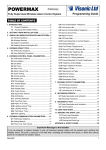
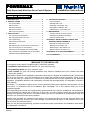
TABLE OF CONTENTS
1. INTRODUCTION .......................................................... 2
2. SPECIFICATIONS ..................................................... 2
2.1 General Data .......................................................2
2.2 RF Section...........................................................2
2.3 Electrical Data .....................................................2
2.4 Communication ...................................................2
2.5 Physical properties ..............................................2
3. INSTALLATION .......................................................... 3
3.1 Unpacking the Equipment ...................................3
3.2 Supplying Power to the Unit ................................3
3.3 Programming.......................................................4
3.4 Mounting the Bracket ..........................................4
3.5 Wiring ..................................................................5
3.6 Attaching the Control Panel to the Bracket .........5
3.7 Connecting the AC Transformer..........................6
3.8 Detectors Compatible with the PowerMax ..........6
3.9 Transmitters Compatible with the PowerMax......6
3.10 Mounting the RS232 Module.............................7
4. TESTING PROCEDURES .......................................... 8
4.1 Preparations ....................................................... 8
4.2 Diagnostic Test................................................... 8
4.3 Keyfob Transmitter Test ..................................... 8
4.4 Appliance ON/OFF Test ..................................... 8
4.5 Emergency Transmitter Test .............................. 8
5. MAINTENANCE .......................................................... 9
5.1 Dismounting the Control panel ........................... 9
5.2 Replacing the Backup Battery ............................ 9
5.3 Fuse Replacement ............................................. 9
APPENDIX A. DETECTOR DEPLOYMENT AND
TRANSMITTER ASSIGNMENTS ............................. 10
A.1 Detector Deployment Plan ............................... 10
A.2 Keyfob Transmitter List .................................... 10
A.3 Emergency Transmitter List ............................. 11
A.4 Non-Alarm Transmitter List .............................. 11
APPENDIX B. X-10 UNIT ASSIGNMENTS ................... 11
FCC STATEMENTS ....................................................... 12
MESSAGE TO THE INSTALLER
The PowerMax control panel is supplied with 3 instruction manuals:
" Installation Instructions (this manual - for your exclusive use)
" Programming Guide (for your exclusive use)
" User’s Guide (for your use during installation only. Must be handed over to the master user after
testing the system).
Appendices A and B to the installation instructions will help you prepare an installation plan. Please take
time to fill out the forms - your job will become much easier and confusion will be prevented. Filling out the
forms will also help you create a list of detectors and transmitters that must be obtained for the particular
application. Compatible detectors and transmitters are listed and described briefly in Paragraphs 3.8 and 3.9
of this manual.
Remember - it is advisable to power up the control panel temporarily after unpacking and program it on the
work bench, in accordance with the installation plan. Paragraph 3.3 of this manual refers you to the
programming guide.
The programming flow charts in the programming guide show all of the options available for each parameter.
Factory defaults are marked with a dark box to their right, and other options (those that can be selected
instead) are marked by clear boxes. This method allows you to put a checkmark in the appropriate clear box
whenever you deviate from the factory defaults.
Although time and date are considered user settings, we recommend that you set the time and date in the
course of programming. Access to the “User Settings” is possible through item 9 on the installer‘s menu (see
User’s manual for exact procedure).
When you are through programming, proceed to install the system as detailed in the Installation Instructions,
from paragraph 3.4 onward.
DE5450
1
1. INTRODUCTION
The PowerMax is a user and installer-friendly, 30-zone
fully-supervised wireless control panel. The system is
designed to function in a way that appeals to the user but
also offers features that make installers’ life easier than
ever before:
EASY TO INSTALL
• Plug-in terminal blocks can be wired while detached
from the unit.
• Quick attach-detach TELCO sockets for telephone line,
telephone set and X-10 controller.
• Special wall-mounted bracket permits installation without
having to open the unit’s cabinet.
• Optional plug-in RS-232 module for local computer.
EASY TO MAINTAIN
• Status, alarm memory and trouble data displayed upon
request.
• Diagnostic test provides visual and audible indication of
the signal level of each detector.
• Remote control and status verification from distant
telephones.
• Event log stores and displays information on 100 past
events.
• Upload / download from distant computer via telephone
line and modem.
• Backup battery uses standard, easily obtained cells.
QUICK PROGRAMMING
• Multiple-choice selection of options for each parameter.
• Unequivocal visual prompts and audio signals
• The installer can gain access to the user menu.
A fully equipped alarm system based on the PowerMax
consists of the units shown in Figure 2 of the user’s guide.
2. SPECIFICATIONS
2.1 General Data
Number of Zones: 29 wireless, 1 hardwired (zone No. 30).
Hardwired Zone Requirements: 2.2 kΩ E.O.L. resistance
(max. resistance of wires 220 Ω).
Zone Types: Interior, perimeter, delay 1, delay 2, 24 hours audible, 24 hours - silent, fire, non-alarm and emergency.
User Codes: 8 codes, 4 digits each
Control Facilities:
- Integral keypad,
- PowerCode / Code-Secure™ hand-held transmitters,
- Remote telephone,
- Local or remote computer.
Display: Single line, back lighted 16-character LCD and 4
LED indicators
Arming Modes: AWAY, HOME, AWAY-INSTANT
HOME-INSTANT, LATCHKEY, FORCED.
Alarm Types: Silent alarm, siren alarm or sounder
(internal) alarm, in accordance with zone attributes.
Siren Signals: Continuous (intrusion / 24 hours / panic);
triple pulse - pause - triple pulse... (fire).
Siren Timeout: Programmable (4 minutes by default)
Internal Sounder Output: at least 85 dBA at 10 ft (3 m)
Supervision: Programmable time frame for inactivity alert
Special Functions:
- Speech and sound control
- Powerline Carrier Device Control (up to seven X-10
brand units) by various factors, as programmed.
- Chime zones
- Diagnostic test and event log
- Remote control by telephone
- Computer control and data download/upload
- Calling for help by using an emergency transmitter
- Tracing inactivity of elderly, physically handicapped and
infirm people.
- Two-way voice communication
Data Retrieval: Status, alarm memory, trouble, event log.
Real Time Clock: The control panel keeps and displays
time and date.
2
Compliance with Standards:
UL1023 - household burglar alarm system unit - Grade A
UL1635 - digital alarm communicator system unit - Grade C
Note: FCC Statements are printed at the end of this manual.
2.2 RF Section
Operating Frequencies: 315 MHz or other UHF channels
per local requirement in the country of use.
Receiver Type: Super-heterodyne, fixed frequency
Receiver Range: 600 ft (180 m) in open space
Coding: PowerCode and/or CodeSecure™
2.3 Electrical Data
Power Supply: Plug-in transformer. 120 VAC, 60 Hz /
9 VAC, 700 mA (12VA).
Note: For UL installation, one of the two following
transformers must be used:
A. Dongguan Oriental Hero Electrical - type OH-41073AT
B. Good Power Electronics Ltd. - type GPA-41-3498
Current Drain: Approx. 95 mA standby, 500 mA at full
load and in alarm.
Sounder Output Current Supply Capability
Internal: 30 mA max.
External: 145 mA max.
PGM (auxiliary) Outputs Current Sinking: 100 mA max.
Fuse Ratings: 1A for battery protection; 0.5 A for siren /
sounder circuit protection.
Backup Battery (provides power for at least 4 hours)
Option 1 - 9V, six alkaline AA cells, 1.8 Ah
Option 2 - 7.2 V, six Nickel Cadmium rechargeable AA
cells, 650 mA/h
Note: For UL installation, the following cell types must be
used:
Alkaline Cells - Golden Power GLR6A or XIAMEN LR6/AA
Rechargeable Cells - Golden Power KR650AA1
Battery Test: Once every 24 hours, and once per hour
during AC power loss.
DE5450
2.4 Communication
Data Transfer to Local Computer: Via RS232 serial port
Report Destinations: 2 central stations, 4 private
telephones, 1 pager
Reporting Format Options: SIA, Pulse 4/2 1900/1400
Hz, Pulse 4/2 1800/2300 Hz, Contact ID
Pulse Rate: 10, 20, 33 and 40 pps - programmable
Message to Private Phones: Tone or voice
Message to Pager: PIN No.#Alarm Type #Zone No.
Built-in Modem: 300 baud, Bell 203 protocol
2.5 Physical Properties
Operating Temp. Range: 32°F to 120°F (0°C to 49°C)
Storage Temp. Range: -4°F to 140°F (-20°C to 60°C)
Humidity: 90% relative humidity, @ 30°C (86°F)
Size: 9-13/16 x 7-1/2 x 1-3/4 in. (250 x 190 x 44 mm).
Weight: 2 pounds (905 g) less batteries
Color: Ivory and charcoal gray
3. INSTALLATION
3.1 Unpacking the Equipment
Open the cardboard packing box and check whether all
the following items are included:
Item
Quantity
PowerMax Control Panel
120 VAC-to-9 VAC Power Transformer
Alkaline cells or Ni-Cd battery cells, size AA
Wireless PIR K-940 MCW or K-980 MCW
Wireless Magnetic Contact Detector MCT-302
4-button Keyfob Transmitter
1
1
6
1
2
1
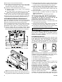
B. Turn the handle slightly to force the right edge of the
cover up. This should dislodge the two catches and
release the right edge of the cover.
WARNING! Do not attempt to dislodge the left side
of the cover first! This will inevitably break the leftside angled legs.
C. Swing the cover up as shown in Figure 2, then pull free
the angled legs at the left and put the cover away. The
inner lid will now be in full view (see Figure 3).
If you find out that an item is missing, contact your vendor
or dealer immediately.
3.2 Supplying Power to the Unit
Enrolling the transmitting devices’ identification codes in
the PowerMax memory is easier to carry out before actual
installation, with all detectors near the control panel,
preferably on a work bench. It is therefore necessary to
power up the PowerMax temporarily from the original
power transformer or from its backup battery.
To utilize the power transformer, use a screwdriver to a
connect a twisted pair between the transformer’s 9 VAC
screw terminals and the 9 VAC POWER terminals of the
PowerMax. The latter are located in the rectangular
opening at the back of the cabinet (see Figure 10). Then
plug the power transformer into a 120 VAC wall outlet.
To power up the control panel from the backup battery,
proceed as follows:
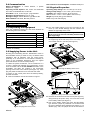
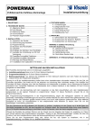
A. Insert a screwdriver into the slot shown in Figure 1.
Figure 2. Removing the Battery Area Cover
Figure 3. Battery Area after Cover Removal
Figure 1. Prying the Cover Loose
DE5450
D. Remove the screw that secures the lid (see Figure 3),
swing the lid up and pull it away. You now have access
to the battery holder (see Figure 4).
E. Pull out the battery holder and check that the battery
type selection jumper is positioned in accordance with
the type of batteries being installed (see Figure 4). For
alkaline (dry) cells, the jumper should be mounted on
3
the two lower pins. For Nickel Cadmium (rechargeable)
cells - on the two upper pins.
CAUTION! Verify that the jumper is at the
correct position for the actual battery cells
being installed.
provided across the rear of the cabinet. Quick mounting of
the PowerMax is possible by virtue of a special bracket
and a unique mechanical system.
The control panel comes with the bracket in place at the
rear. Since a catch at the lower end of the bracket is
trapped (intentionally) within the cabinet, a special
technique must be used to release it (see Figures 6 & 7).
Figure 4. Battery Type Selection Jumper
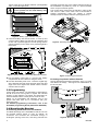
F. Insert all 6 battery cells into the holder - 3 at the top and
3 at the bottom. Make sure that the flat (negative) end
of each cell is pressed against a circular spring and the
capped (positive) end of each cell is pressed against a
flat contact.
Figure 5. Battery Holder in Place with Batteries Installed
G. Put the battery holder back in, re-mount the battery
compartment lid and re-attach it using the screw.
H. Put back the battery area cover - insert the angled legs
at the left edge into their holes and then press the right
edge of the cover against the cabinet surface until the
catches click into place.
Figure 6. Releasing the Bottom Catch from the Trap
Figure 7. Detaching the Bracket
B. Getting Acquainted with the Bracket
Having detached the bracket successfully, put it on a desk
and observe its design - see Figure 8 for identification of
its various parts.
3.3 Programming
It pays off to plan ahead - use the tables in appendices A
and B at the end of this guide to register the intended
location of each detector, the holder and assignment of
each transmitter and the control plan for the X-10 units.
Gather up all transmitters and detectors used in the
system and mark each one in accordance with your
deployment plan.
For detailed programming instructions, refer to the
PowerMax programming Guide (Publication DE5450P).
3.4 Mounting the Bracket
A. Detaching the Bracket from the Cabinet
A notable advantage of the PowerMax is that the unit can
be mounted without having to open its cabinet. All
connectors and terminals are accessible through a
rectangular opening at the rear, and wiring channels are
4
Figure 8. Bracket - Front View
DE5450
The two upper mounting holes are intended for regular
attachment to the wall with screws and anchors. The lower
mounting hole, however, accommodates a combined “ring
and cam” piece connected to the bottom leg of the bracket
by 3 breakable plastic joints.
A special plastic washer supplied with the bracket must be
inserted into the ring to complete the lower mounting hole.
With the washer in place, a third screw can be used to
secure the bottom leg of the bracket to the wall.
Once the control panel is mounted in place, the cam
enters a slot in the control panel’s rear part and maintains
the built in tamper switch pressed. Separating the control
panel from the bracket will start a tamper alarm. Forced
removal of the entire assembly off the wall will also start a
tamper alarm, because the joints of the ring and cam
piece to the bracket will break off, leaving the ring and
cam attached to the wall.
The telephone-type connectors are also easy to deal with,
because of their quick attach/detach capability.
IMPORTANT! The earth ground terminal must be
connected to a good earth ground to allow effective
protection against lightning transients.
Following are two examples of good earth connections:
Cold-water metal pipe: Connect the earth wire to the
pipe, using a non-corrosive metal strap (preferably
copper), firmly secured to the pipe.
AC Power outlet ground: This ground is available in
3-prong, 120 VAC outlets. Test the validity of the ground
terminal with a 3-wire circuit tester that has neon lamp
indicators (UL Listed Ideal Model 61-035 or equivalent,
available from electrical supply stores).
C. Attaching the Bracket to the Wall
Choose a concealed place, yet easily accessible to
prospective users of the alarm system. Make sure that an
uninterrupted AC power outlet and a telephone line socket
are available near the installation spot.
Use the bracket as a template to mark the drilling points.
Drill the holes and attach the bracket to the wall with 3
screw. Be sure to insert the special plastic washer into the
ring in the bottom hole, as shown in Figure 8.
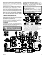
3.5 Wiring
All terminals and connectors are accessible within the
opening at the back of the PowerMax (see Figure 9). All
screw terminal blocks (except for “EARTH”) can be pulled
out, wired appropriately and plugged back in.
WARNING! When plugging terminals back
into place, be sure to align them carefully
with the pins on the PCB. Misaligned or
reverse insertion of terminals may damage
internal PowerMax circuits!
Figure 9. Sunken Wiring Area Layout
For telephone type connectors, you will need these items:
• A length of 6-lead, color coded modular cable.
• An length of 8-lead, color coded modular cable.
• Two 6-position RJ-11 plugs and one 8-position RJ-31X
plug, to terminate the cables at the PowerMax end.
• A crimping tool for RJ-11 and RJ-31X plugs.
Figure 10. Wiring Diagram
DE5450
5
Refer to Figure 10 and proceed as follows:
A. Extract the screw terminal blocks one by one and make
the necessary connections. When done, plug each
terminal block onto its PCB mounted pins.
B. Prepare the cable assemblies that connect the:
" Powerline carrier (X-10) socket to the Powerline
interface module,
" The LINE socket to the telephone line (or the LINE
& SET socket to the line and local telephone set).
C. Mate the RJ-11 and RJ-31X plugs with their respective
jacks. Do not confuse the X-10 plug with the LINE plug.
D. Route the wires via the wiring channels at the back.
With all wires properly seated, proceed to Para. 3.6.
3.6 Cabinet-to-Bracket Attachment
Once all connections are made and the wires are seated
within the channels at the rear, it is only necessary to
attach the control panel to the wall-mounted bracket.
Having separated the bracket from the cabinet (see Para.
3.4.), you already have a notion of what has to be done.
Nevertheless, refer to Figure 11 and proceed as follows:
A. Hold the cabinet with its top slightly slanted toward
yourself and align the trap at the bottom of the cabinet
with the dual-prong catch at the bottom of the bracket.
C. Using the dual prong catch as a pivot, bring the top of
the cabinet closer to the wall, allowing the two hangers
to enter the two corresponding holes in the cabinet.
D. Once the cabinet is flush against the bracket, slide it
down as far as the hangers will allow (about 10 mm).
The dual prong catch at the bottom should snap into
place with a click.
E. Test the assembly by lightly pulling the cabinet away
from the wall. If correctly mounted, the cabinet will
adhere to the bracket.
Note: See Para. 5.1 for dismounting procedure.
3.7 Connecting the AC Transformer
CAUTION! Do not plug the transformer into the AC
outlet before completing all other wiring.
A. Remove the center screw from the AC wall outlet.
B. Plug the transformer directly in - the Power LED of the
control panel should illuminate.
C. Use the screw removed in Step A above to secure the
transformer to the AC outlet. Tighten the screw well.
A. The distance of the transformer from the system should
not exceed 150 ft using 18 AWG conductors.
For UL installation, do not connect to a receptacle
controlled by a switch.
3.8 PowerMax-Compatible Detectors
Each detector compatible with the PowerMax system is
packed with its own installation instructions. Read them
carefully and install as indicated.
A. PIR Motion Detectors
The wireless passive infrared (PIR) motion detectors used
in the system are of the PowerCode type, using a unique
24-bit identification code. The PowerMax is capable of
“learning” each detector’s identification code and linking it
to a specific zone (see Section 3 in the Programming
Manual). Some units are shown in Figures 13, 14 and 15.
Figure 11. Cabinet-to-Bracket Assembly - Top View
Figure 14. MC/PIR-3000
Figure 13.
Figure 15.
or K-940MCW
MC/PIR-2000
K-980MCW
Note: K-940 MCW and K-980MCW are pet immune units.
In addition to its unique identification code, each detector
transmits a message containing status information:
• The detector is in alarm (or not).
• The detector is being tampered with (or not).
• The battery voltage is low (or normal).
• “This is a supervisory message”.
If any of these detectors detects motion, it sends out a
message to the alarm control panel. If the system is in the
armed state, an alarm will be triggered.
Figure 12. Cabinet-to-Bracket Assembly - Side View
B. Allow the dual prong catch to enter the trap as far as it
will go while the cabinet is slanted towards your stomach.
6
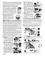
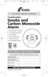
B. Magnetic Contact Transmitter
The MCT-302 (see Figure 16) is a PowerCode magnetic-contact transmitter used to
detect the opening of a door or a window.
The alarm contacts are closed as long as
Figure 16.
the door or window remain closed.
MCT-302
In addition, the unit has an extra alarm input that behaves
as if it were a separate wireless transmitter. This type of
DE5450
detector sends (or does not send) a “restored to normal“
message to the alarm system, depending on the setting of
an on-board “DIP” switch. The “restore” message informs
you, through the alarm system’s front panel indicators,
whether the door or window is open or closed.
C. Wireless Adapter for Wired Detectors
MCT-100 (see Fig. 17) is a PowerCode
device used mainly as a wireless adapter
for 2 regular magnetic switches installed on
2 windows in the same room. The unit has
two inputs, behaving as separate wireless
transmitters and transmitting different
PowerCode IDs. Each input sends (or
does not send) a “restored“ message to
the alarm system, depending on the
Figure 17.
setting of an on-board “DIP” switch.
MCT-100
D. Wireless Smoke Detector
(unapproved by UL). This is a
photoelectric smoke detector
equipped with a PowerCode-type
transmitter. When enrolled to a
fire zone, it initiates a fire alarm
Figure 18. MCT-423
upon detection of smoke.
3.9 PowerMax-Compatible Transmitters
Note: Each transmitter is packed with its own instructions
for battery installation and use. Be sure to pass these
documents on to the “Master User“ of the alarm system.
The PowerMax system is compatible with multi-button and
single button key-ring and hand-held transmitters that use
PowerCode and CodeSecure coding methods.
Multi-button PowerCode transmitters transmit the same
code each time the same button is pressed. They can be
used for emergency signaling, or for activating the PGM
output or for controlling appliances via X-10 units. They
can not be used for arming / disarming.
CodeSecure transmitters are of the rolling code type - they
transmit a new code each time the same button is
pressed. This provides a higher security level, especially
in arming / disarming applications, because the code can
not be copied (“grabbed”) by unauthorized people.
Following are the basic details of several compatible
transmitters. The possible applications for each pushbutton are indicated in each drawing.
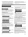
A. MCT-234 (Fig 19): ‘Keyfob’
transmitter - one unit is
supplied with the PowerMax.
You can program the AUX
(auxiliary) button to perform
various tasks, in accordance
with the user’s needs.
Figure 19. MCT-234
B. MCT-231 / MCT-201 (Fig.
20): Single-button pendant
units. The MCT-231 (CodeSecure) and the MCT-201
(PowerCode) can be enrolled
to perform functions as
shown. Both units look alike. Figure 20. MCT-231 / 201
C. MCT-134 / MCT-104 (Fig.
21): 4-button hand-held units.
MCT-134 (CodeSecure) can
replace the MCT-234 keyfob.
MCT-104 (PowerCode) can
perform emergency and nonalarm functions. Both units
Figure 21. MCT-134 / 104
look alike.
DE5450
D. MCT-132 / MCT-102 (see
Fig. 22): 2-button units.
MCT-132 (CodeSecure) Can
perform functions as shown.
MCT-102 (PowerCode) can
perform emergency and nonalarm functions. Both units
Figure 22. MCT-132 / 102
look alike.
E. MCT-131 / MCT-101 (see
Fig. 23): Single-button units.
The MCT-231 (CodeSecure)
and the MCT-201 (PowerCode) can be enrolled to
perform functions as shown.
Both units look alike.
Figure 23. MCT-131 / 101
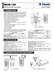
F. MCT-211 (see Fig. 24) This
is a waterproof, wrist-worn
PowerCode transmitter, that
can be enrolled to perform
emergency or non-alarm
Figure 24. MCT-211
function.
3.10 Mounting the RS232 Module
The control panel can be equipped with an optional RS232
module that allows serial data interchange with a local
computer. If this module is not supplied, a special plastic
cap blocks the cable entry to the niche designed to
accommodate the module.
The following instructions are useful when adding the
RS232 module to an already installed PowerMax system:
A. Detach the cabinet from the bracket (see Para. 5.1)
B. Remove the factory installed plastic cap by sliding it out
along the grooves as shown in Figure 25.
Figure 25. Removing the Cap from the RS232 Niche
C. Align the RS232 module with the grooves and the
module catches as shown in Figure 26.
Figure 26. Inserting the RS232 Module
7
D. Push the module all the way in, making sure that the
4-pin socket mates with the 4-pin header at the bottom.
Note: When the module is properly seated, the module
catches that were pushed aside during insertion spring
back into place above the top edge of the module.
E. Prepare an RS-232 flat modular cable and terminate it
with a 6-position RJ-11 plug at the PowerMax end.
Terminations at the computer’s end may vary.
F. Mate the plug with the RJ-11 socket and bend the cable
backward to pass it out via the wiring channel.
G. Re-attach the control panel to the bracket, as
instructed in Para. 3.6.
4. TESTING PROCEDURES
4.1 Preparations
Make sure all protected windows and doors are closed. If
all zones are secured (undisturbed), the display should
read:
HH:MM
READY
If the system is “NOT READY”, query the control panel by
pressing the <SHOW/OK> button repeatedly. The
source(s) of the problem(s) will be displayed and read
aloud. Take the necessary measures to eliminate the
problem(s) before testing the system (see 4.2 below).
4.2 Diagnostic Test
To verify proper function of all detectors in the system, a
comprehensive diagnostic test is required. To perform this
test, you must access Item No. 8 in the installer’s menu
the same way as you did when you programmed the
control panel:
A. Click the <NEXT> button until the display reads:
INSTALLER MODE
B. Click <OK> to select the installer’s menu. The control
panel will prompt you for the installer code.
C. Enter the valid installer code (9#9#9#9) or the new
installer code that you already programmed). The
“Happy Tune” (- - - ––––) will sound if the code is
correct and the display will change to:
1.NEW
INSTL
CODE
D. Click <NEXT> or <BACK> until the number and name
of the desired mode is displayed:
8.
DIAGNOSTICS
E. Carry on as in Section 9 of the programming guide.
4.3 Keyfob Transmitter Test
Initiate transmission from each transmitter enrolled as a
keyfob unit (according to the list in Table A2, Appendix A).
Use each transmitter to arm the control panel AWAY and
immediately disarm it. Upon pressing the keyfob unit’s
AWAY key, the ARM indicator should light, and the display
should respond as follows:
ARMING
AWAY
$
PLEASE EXIT NOW
and the exit delay beeps will begin.
Press the keyfob unit’s DISARM ( ) key. The ARM
indicator should extinguish, the “Happy Tune” (- - - –––)
should sound and the display should revert to:
READY
HH:MM
Test the AUX button in each keyfob in accordance with the
information noted in Table A.2, Appendix A. Verify that the
AUX button performs its duty as programmed.
8
" If the AUX button is defined as “STATUS”, system
status should be displayed and announced upon
pressing the AUX button.
" If the AUX button is defined as “INSTANT”, press the
AWAY button and then the AUX button. The response
should be:
ARMING
INSTANT
(alternating)
PLEASE
EXIT
NOW
and the exit delay beeps will start. Press the DISARM
( ) key immediately to disarm.
" If the AUX button is programmed as “PGM / X-10” and
permitted to activate one or several X-10 units,
pressing the AUX button should activate the appliance
controlled by the chosen X-10 unit(s).
" If the AUX button is programmed as “PGM / X-10” and
permitted to activate the PGM output, pressing AUX
should activate the device wired to the PGM output.
4.4 Appliance ON/OFF Test
The “X-10 unit assignment” information that you noted in
Appendix B to this manual is very useful for this test.
Go over the table in Appendix B column by column. If, for
instance the “ON by arming” column has “X”s marked in
the rows pertaining to units 1, 5 and 7 - then arm the
system and verify that the appliances controlled by these
units are actually activated upon arming.
Continue in the same manner in the following columns,
always creating the state or event that will activate the
relevant units. Verify that all appliances are activated as
programmed.
IMPORTANT! Before testing “On by Timer” and “On by
Zone”, make sure that these forms of control are permitted
repeatedly and verify that the display shows:
- click
BY
TIMER
BY
SENSOR
ON
and:
ON
A dark box at the extreme right means that these functions
are enabled.
The easiest way to test timed activation is to select the
ninth item in the installer’s menu (”9. USER SETTINGS”)
and set the system clock a few minutes before the relevant
“start time”. Do not forget to return the clock to the correct
time after completion of this test.
4.5 Emergency Transmitter Test
Initiate transmission from each transmitter enrolled to an
emergency zone (according to the list in Table A3,
Appendix A). For example, upon pressing the transmit
button of an emergency transmitter enrolled to zone 22,
the display should read:
DE5450
Z22
EMERGENCY
(alternating)
VIOLATED
It is advisable to let the central station know that you are
conducting this test, or just disconnect the telephone line
from the PowerMax during this test, to prevent false
alarms.
5. MAINTENANCE
5.1 Dismounting the Control Panel
A. Insert a wide bladed screwdriver into the hole at the
bottom of the unit (see Figure 27).
Replacement and first-time insertion of cells are similar
The only difference is the necessity to remove the old cells
and to inspect the battery holder contacts and springs for
signs of corrosion.
If corrosion is found in the battery holder, clean it first with
a piece of cloth dampened with hot water and then file the
contacts clean until they shine. In extreme cases, the
entire battery holder should be replaced.
With fresh battery cells and correct insertion, the
TROUBLE indicator should extinguish. However, the
“MEMORY” message will now blink in the display (caused
by the “tamper” alarm you triggered when opening the
battery compartment lid). Clear it by arming the system
and immediately disarming.
5.3 Fuse Replacement
Figure 27. Releasing the Catch
B. Turn the screwdriver’s handle to free the catch from the
trap and at the same time slide the control panel about
10 mm up along the bracket.
C. After sliding the cabinet up, remove the screwdriver and
pull the upper part of the cabinet away from the
bracket, slanting it towards yourself.
D. With the cabinet free of the hangers you can pull the
bottom of the cabinet away and free it from the dual
prong catch at the bottom of the bracket.
The PowerMax has two fuses which can be replaced if
burnt out:
" Battery Fuse - 1 A, time delay type, UL recognized
" Sounder Fuse - 0.5 A, time delay type, UL recognized
If any one of the fuses burns out, the trouble indicator
lights and TRBL is displayed (together with READY or
NOT READY - as the case may be). Clicking the <SHOW
/OK> button will display a FUSE TROUBLE message.
Two fuses are accessible through the rectangular opening
at the rear of the cabinet (see figure 29). To replace a
fuse, the cabinet should be temporarily dismounted (as
described in Para. 5.1 above).
5.2 Replacing the Backup Battery
CAUTION! If you replace rechargeable cells
with alkaline (dry) cells, be sure to install the
battery-type jumper in the “DRY” position.
Failure to do so will result in rapid cell
destruction and leakage (acid leakage may
cause further damage).
Figure 29. Fuse Locations
Extract the two fuses one by one and check them visually.
In most cases, a defective fuse can be identified by the
broken conductor within the glass cylinder. If in doubt, test
the continuity of the fuse with an ohmmeter.
Replace a defective fuse with a new 3AG-type of the same
value. The relevant trouble indications will immediately
disappear.
Figure 28. Jumper in Dry Battery Position
DE5450
9
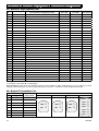
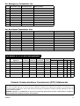
APPENDIX A. Detector Deployment & Transmitter Assignments
A1. Detector Deployment Plan
Zone
No.
Zone Type
Sensor Location or Transmitter Assignment
(in non-alarm or emergency zones)
Chime
(Yes / No)
Controls PGM
Controls
(X = YES)
X-10 Unit No.
1
2
3
4
5
6
7
8
9
10
11
12
13
14
15
16
17
18
19
20
21
22
23
24
25
26
27
28
29
30
Zone Types: 1 = Interior ✹ 2 = Perimeter ✹ 3 = Delay 1 ✹ 4 = Delay 2 ✹ 5 = 24 h silent ✹ 6 = 24 h audible ✹
7 = Fire ✹ 8 = Non-alarm ✹ 9 = Emergency.
Zone Locations: Note down the intended location for each detector. When programming, you may select one of 26
available zone names (plus 3 custom zone names that you can add - see Figure 3 in the Programming Guide).
A2. Keyfob Transmitter List
No.
Transmitter
Type
Name of Person
Responsible
Status
AUX Button Assignment
Instant
Outputs: PGM
1
Unit 1
2
3
4
5
6
7
8
10
Outputs: X-10
Unit 2
YES
❒
YES
❒
YES
❒
NO
❒
NO
❒
NO
❒
Unit 3
Unit 4
Unit 5
Unit 6
Unit 7
❒
❒
❒
❒
❒
❒
❒
DE5450
A3. Emergency Transmitter List
Tx #
Transmitter Type Enrolled to Zone
Name of holder
1
2
3
4
5
6
7
8
9
10
A4. Non-Alarm Transmitter List
Tx #
Transmitter Type Enrolled to Zone
Name of holder
Assignment
1
2
3
4
5
6
7
8
9
10
APPENDIX B. X-10 Unit Assignments
Unit
No.
Controlled
Appliance
ON
ON
by Arming by Memory
ON
by Keyfob
ON
by Delay
ON by Timer
ON Time OFF Time
ON by Zone No.
a
b
c
1
2
3
4
5
6
7
Federal Communications Commission (FCC) Statements
FCC PART 15 STATEMENT
This device complies with Part 15 of the FCC Rules. Operation is subject to the following two conditions: (1) This device may
not cause harmful interference, and (2) This device must accept any interference received, including interference that may
cause undesired operation.
WARNING! Changes or modifications to this unit not expressly approved by the party responsible for compliance
could void the user's authority to operate the equipment.
DE5450
11
The digital circuits of this device has been tested and found to comply with the limits for a Class B digital device, pursuant to
Part 15 of the FCC Rules. These limits are designed to provide reasonable protection against harmful interference in
residential installations. This equipment generates, uses and can radiate radio frequency energy and, if not installed and used
in accordance with the instructions, may cause harmful interference to radio and television reception. However, there is no
guarantee that interference will not occur in a particular installation. If this device does cause such interference, which can be
verified by turning the device off and on, the user is encouraged to eliminate the interference by one or more of the following
measures:
– Re-orient or re-locate the receiving antenna.
– Increase the distance between the device and the receiver.
– Connect the device to an outlet on a circuit different from the one which supplies power to the receiver.
– Consult the dealer or an experienced radio/TV technician.
FCC PART 68 STATEMENT
This equipment complies with Part 68 of the FCC rules. On the front cover of this equipment is a label that contains, among
other information, the FCC registration number and ringer equivalence number (REN) for this equipment. If requested, this
information must be provided to the telephone company.
This equipment uses the following jacks: An RJ31X is used to connect this equipment to the telephone network. The REN is
used to determine the quantity of devices which may be connected to the telephone line. Excessive RENs on the telephone
line may result in the devices not ringing in response to an incoming call. In most, but not all areas, the sum of the RENs
should not exceed five (5.0). To be certain of the number of devices that may be connected to the line, as determined by the
total RENs, contact the telephone company to determine the maximum REN for the calling area. If this equipment causes
harm to the telephone network, the telephone company will notify you in advance that temporary discontinuance of service
may be required. If advance notice is not practical, the telephone company will notify the customer as soon as possible. Also,
you will be advised of your right to file a complaint with the FCC if you believe necessary. The telephone company may make
changes in its facilities, equipment, operations, or procedures that could affect the operation of the equipment. If this happens,
the telephone company will provide advance notice that will enable you to make the necessary modifications in order to
maintain uninterrupted service.
If trouble is experienced with this equipment, please contact the manufacturer for repair and warranty information. If the
trouble is causing harm to the telephone network, the telephone company may request that you remove the equipment from
the network until the problem is resolved.
There are no user serviceable components in this product, and all necessary repairs must be made by the manufacturer.
Other repair methods may invalidate the FCC registration on this product.
This equipment cannot be used on telephone company-provided coin service. Connection to Party Line Service is subject to
state tariffs.
When programming or making test calls to an emergency number, briefly explain to the dispatcher the reason for the call.
Perform such activities in the off-peak hours; such as early morning or late evening.
WARRANTY
Visonic Ltd. and/or its subsidiaries and its affiliates ("the Manufacturer") warrants its
products hereinafter referred to as "the Product" or "Products" to be in conformance with
its own plans and specifications and to be free of defects in materials and workmanship
under normal use and service for a period of twelve months from the date of shipment by
the Manufacturer. The Manufacturer's obligations shall be limited within the warranty
period, at its option, to repair or replace the product or any part thereof. The Manufacturer
shall not be responsible for dismantling and/or reinstallation charges. To exercise the
warranty the product must be returned to the Manufacturer freight prepaid and insured.
This warranty does not apply in the following cases: improper installation, misuse,
failure to follow installation and operating instructions, alteration, abuse, accident or
tampering, and repair by anyone other than the Manufacturer.
This warranty is exclusive and expressly in lieu of all other warranties, obligations or
liabilities, whether written, oral, express or implied, including any warranty of
merchantability or fitness for a particular purpose, or otherwise. In no case shall the
Manufacturer be liable to anyone for any consequential or incidental damages for breach
of this warranty or any other warranties whatsoever, as aforesaid.
This warranty shall not be modified, varied or extended, and the Manufacturer does not
authorize any person to act on its behalf in the modification, variation or extension of this
warranty. This warranty shall apply to the Product only. All products, accessories or
attachments of others used in conjunction with the Product, including batteries, shall be
covered solely by their own warranty, if any. The Manufacturer shall not be liable for any
damage or loss whatsoever, whether directly, indirectly, incidentally, consequentially or
otherwise, caused by the malfunction of the Product due to products, accessories, or
attachments of others, including batteries, used in conjunction with the Products.
The Manufacturer does not represent that its Product may not be compromised and/or
circumvented, or that the Product will prevent any death, personal and/or bodily injury
and/or damage to property resulting from burglary, robbery, fire or otherwise, or that the
Product will in all cases provide adequate warning or protection. User understands that a
properly installed and maintained alarm may only reduce the risk of events such as
burglary, robbery, and fire without warning, but it is not insurance or a guarantee that such
will not occur or that there will be no death, personal damage and/or damage to property
as a result.
The Manufacturer shall have no liability for any death, personal and/or bodily injury
and/or damage to property or other loss whether direct, indirect, incidental,
consequential or otherwise, based on a claim that the Product failed to function.
However, if the Manufacturer is held liable, whether directly or indirectly, for any loss or
damage arising under this limited warranty or otherwise, regardless of cause or origin, the
Manufacturer's maximum liability shall not in any case exceed the purchase price of the
Product, which shall be fixed as liquidated damages and not as a penalty, and shall be the
complete and exclusive remedy against the Manufacturer.
Warning: The user should follow the installation and operation instructions and among
other things test the Product and the whole system at least once a week. For various
reasons, including, but not limited to, changes in environmental conditions, electric or
electronic disruptions and tampering, the Product may not perform as expected. The user
is advised to take all necessary precautions for his /her safety and the protection of
his/her property.
6/91
VISONIC LTD. (ISRAEL): P.O.B 22020 TEL-AVIV 61220 ISRAEL. PHONE: (972-3) 645-6789, FAX: (972-3) 645-6788
VISONIC INC. (U.S.A.): 10 NORTHWOOD DRIVE, BLOOMFIELD CT. 06002-1911. PHONE: (860) 243-0833, (800) 223-0020. FAX: (860) 242-8094
VISONIC LTD. (UK): UNIT 1, STRATTON PARK, DUNTON LANE, BIGGLESWADE, BEDS. SG18 8QS. PHONE: (01767) 600857 FAX: (01767) 601098
INTERNET: www.visonic.com
VISONIC LTD. 2000
12
POWERMAX
DE5450- (REV. 0, 1/00)
DE5450