1
.3
User’s Guide
Slimline LED Keypad
,1752'8&7,21
Welcome to the world of MAESTRO technology. Your MAESTRO
security system has been designed with ease of use and simplicity
in mind. We have developed an advanced technology security
system with many powerful features that anyone can use without
having to memorizing complex and confusing codes.
The elegant and user-friendly KP-601 keypad allows you to easily
access your security system’s functions at the touch of a key. Its
array of LED indicators provides you with an easy-to-understand
display of your security system’s status.
The area you wish to secure can include as many as 6 or 10 zones
and can be controlled by several KP-601 keypads. Thanks to the
MAESTRO’S partitioning feature, two distinct systems (A and B) can
be created and controlled by the control panel. Partitioning can be
used in installations where shared security systems are more
practical,
such
as
office/warehouse
buildings,
or
apartment/condominium complexes.
The KP-601 keypad’s 20 LED display and keypad sounder serve to
keep you instantly aware of alarm, system and operational status.
Motion, smoke, glass break, as well as vibration/shock detectors
and door/window contact sensors will all report to MAESTRO’S RISC
microprocessor brain and to your monitoring security station. Vital
security information will be communicated to you via the keypad.
The MAESTRO can report a wide range of status conditions to the
central monitoring station. Automatic test reports can also be sent to
the monitoring station to ensure that your system is functioning
properly. We recommend that such tests be conducted regularly.
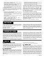
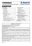
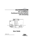
.H\SDG 'LVSOD\
Everything you need to know about your system is clearly displayed
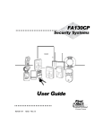
on the KP-601 keypad. The keypad layout (fig. 2) provides you with
an excellent introduction to the roles of each LED indicator and the
keypad function keys. LED indicators labeled 1 to 10 indicate your
system zones status. If a zone indicator is “off”, the status of the
corresponding zone is normal (intrusion was not detected). If the
zone light is "on" (illuminated), means the corresponding zone
intrusion has been detected (i.e. open door, movement detected).
Flashing zone indicator means there is a wiring problem on the
corresponding zone.
Figure 1 - KP-601
.H\SDG ´%HHS 7RQHVµ
Every time a key is pressed, the keypad beeps (0.5 seconds) to
indicate the entry has been accepted. When you enter information
on the keypad, it will guide you with beep tones that indicate
acceptance or rejection of your entries. You should be familiar with
these two keypad beep tones:
Confirmation Beep: When an operation (i.e. arming/disarming) is
successfully entered on the keypad, or when the system switches
to a new status/mode, the sounder produces an intermittent beep
tone (“BEEP-BEEP-BEEP”).
Rejection Beep: When the system reverts to previous status, or
when an operation is incorrectly entered on the keypad, the sounder
emits a continuous beep tone (“BEEEEEEEEP”).
VHFWLRQ Figure 2 - Keypad layout
Note: Using “Ø” key to bypass zone number 10 is accompanied by illumination of “10” LED.
DE5303
1
0$67(5 86(5 $&&(66 &2'(6
In addition to the master code, your Maestro control panel can be
programmed to accept up to 48 user access codes. These access
codes allow users to arm and disarm the security system. You can
choose to use either 4 or 6-digit access codes with your system.
6-digit codes are considered more difficult to “crack” and are
therefore more “secure”. If, however, ease of recall is your priority,
then youR installer can set the security system to accept 4-digit
access codes. Ask your installer about this option. Once your codes
are entered, the security system will never loose these codes even
after total AC and battery failure. Avoid selecting simple or obvious
access codes, such as your telephone number, street address or
codes such as 1234.
&RGH 3ULRULW\
When deciding who should have access to your security system,
please keep in mind that each of the user codes can be assigned a
different code priority. Code priority determines the level of security
access each user will have, and which features and functions they
can activate. User Codes can be programmed to arm/disarm the
system, activate [HOME] or [AWAY] arming, and enter zone bypass
entries. In a partitioned system these codes can be programmed to
arm/disarm “System A”, “System B” zones, or both systems. The
installer will program the code priorities for each user to meet your
specific needs. Note the master code is defaulted to maximum code
priority and can not be altered. This means with the master code
you can arm and disarm the system using any arming method.
&UHDWH'HOHWH $FFHVV &RGHV
NOTE: The default Master Code (00) is 0000.
Only the Master and User Code 01 can create, modify or delete
access codes. If programming a Master Code or a User Code for
the first time, you must use the default master code (0000). If you
make an error while entering an access code simply press [CLR]
key to delete the current entry and re-enter the access code.
To create or modify an Access Code press:
1) [ENT] + [master code or user code 01]. “beep-beep-beep” will
be heard + flash “PRG” indicator.
2) [2-digit code number] (i.e. User Code 8 = 08).
“beep-beep-beep” + “PRG” indicator remains lit*.
3) [4-digit code] + [ENT] or [6-digit code] + [ENT].
“beep-beep-beep” + flash “prg” indicator
4) Return to step 2 to continue programming or press [CLR] to
exit programming mode.
To delete an Access Code press:
1. Repeat steps 1 and 2 above
2. [2ND] “BEEEEEEEEP” + flash “2ND” indicator.
3. [ENT] “BEEP-BEEP-BEEP” + flash “PRG” indicator.
4. Press [CLR] to exit programming mode.
*A flashing “2ND” indicator means the current user code is empty.
'XUHVV &RGH
If unwillingly forced to disarm your system, you can enter User
Code #48 instead of your usual code. This code will disarm the
system and send a silent alert (Duress Code) to the Monitoring
Station. Please verify with your installer if this feature has been
enabled.
$UPLQJ WKH 6\VWHP
The Maestro security systems can be armed using one of 7
different methods designed to cover a variety of security situations.
We suggest that you familiarize yourself with all arming methods so
that you can take full advantage of your system. All arming methods
are preceded by an exit delay period - the period the control panel
will wait before arming the system after having entered a valid
access code. Your installer will program the exit delay duration
based on the time you require to safely exit the protected area once
the code has been entered.
What is “Regular” arming?
This method, commonly used for day-to-day arming, will arm all the
zones in the system.
Regular” arming process:
When the green “ready” indicator is illuminated, simply enter a
VALID ACCESS CODE.
How does “Regular” arming work?
The keypad’s green "ready" light must be illuminated, indicating that
all zones are closed (normal). All doors and windows must be
closed, and there can be no movement in areas monitored by
motion detectors. If you make a mistake entering your code or if the
ready indicator is not on when the code was entered, the keypad will
emit a “rejection beep” (beeeeeeeep).
When you have correctly entered your user code, the keypad will
sound a “confirmation beep” (beep-beep-beep) and the red "ARM"
indicator will illuminate. The "READY" light will flash and the keypad
will "beep" (if programmed) during the exit delay period. During the
final 10 seconds of the exit delay, the keypad will “beep” faster and
the “ready” indicator will flash at a faster rate. At the end of exit
delay, the keypad will sound a “confirmation beep”, the green
“READY” indicator will extinguish and the red “ARM” indicator will
remain illuminated to indicate that the system is armed.
partially arming the system. This means that you can stay in and
move around your home, while certain designated zones are armed.
For example, entry/exit points like doors or windows, the basement,
or perhaps all the zones on the perimeter of the establishment may
be armed when going to sleep at night, while other zones remain
deactivated. Based on your instructions, your installer programs the
control panel to arm only specific zones when “home arming” the
system. These specific zones are called “home” zones and these
programmed “home zones” can only be changed by your installer.
“Home” arming can also be activated using a keyswitch or
pushbutton (See section 3.6)
“HOME” ARMING PROCESS:
1. Verify that all “home” zones are closed. No need to wait for
“READY” indicator.
2. Press [HOME] + [VALID ACCESS CODE]
How Does Home Arming Work?
Unlike regular arming, the green “READY” indicator does not have to be
illuminated. Only doors and windows programmed as “home zones”
must be closed, and there can be no movement in areas monitored by
motion detectors in “home zones”. If you make a mistake entering your
code, if a “home zone” was open when the code was entered or if you
were not given “home” arming code priority, the keypad will emit a
“rejection beep” (beeeeeeeep).
When you have correctly entered your user code, the keypad will
emit a “confirmation beep” (beep-beep-beep), the red "home" and
"ARM" indicators will illuminate and the green "READY" indicator
will flash during the exit delay period. The keypad will not “beep”
during the exit delay. During the final 10 seconds of the exit delay,
the “READY” indicator will flash at a faster rate.
At the end of the exit delay, the keypad will emit a “confirmation
beep”, “READY” indicator will stop flashing and RED “HOME” and
“ARM” indicators will remain illuminated. Note, to use this method
the user must have “home” arming priority (see section 2.1).
What is “Home” Arming?
“Home” arming allows you to remain in the protected area while
What is “Away” arming?
“Away” arming allows system rapid arming without waiting for the
5HJXODU $UPLQJ
´+RPHµ $UPLQJ
2
$ZD\ )RUFHG $UPLQJ
DE5303
green “READY” indicator. Any open zones at the time of arming will
be considered “deactivated” by the control panel. Therefore, these
zones will not generate an alarm. If during this period a “deactivated”
zone is closed, the control panel will revert that zone to “active”
status, hence, will generate an alarm as a result of intrusion.
“Away” forced arming process:
1. No need to wait for “READY” indicator.
2. Press [AWAY] + [VALID ACCESS CODE]
How does “Away” arming work?
Simply press the [AWAY] key followed by a valid user access code. If you
make a mistake entering your code or if you were not given “away”
arming code priority, the keypad will emit a “rejection beep”
(BEEEEEEEEP). When you have correctly entered your user code, the
keypad will emit a “confirmation beep” (BEEP-BEEP-BEEP) and the red
"ARM" indicator will illuminate. The "READY" light will flash and the
keypad will "beep" (if programmed) during the exit delay period. During
the final 10 seconds of the exit delay, the keypad will “beep” faster and
the “READY” indicator will flash at a faster rate. At the end of the exit
delay, the green “READY” indicator will stop flashing and the red “ARM”
indicator will remain illuminated. Note, to use this method the user must
have “away” arming priority, see Code Priority (section 2.1).
0DQXDO =RQH %\SDVVLQJ
What is zone bypassing?
When a zone is bypassed, it will no longer be monitored by the control
panel. Hence, the zone is considered “deactivated” and will not generate
an alarm when breached. You may wish to bypass certain zones when,
for example, workers are renovating part of your establishment. Manual
zone bypassing instructs the control panel to ignore (“deactivate”)
specified zones in order to arm the remainder of the system. Only zones
programmed by your installer as “bypass-enabled” can be bypassed.
Please note, the control panel can not bypass fire zones.
Manual zone bypassing process:
1. Press [bypass] + [valid access code]Yellow “bypass” indicator
will flash
2. Illuminate zone indicators corresponding to zones you wish to
bypass by pressing the respective key
3. Press [ENT]; “bypass” indicator will remain illuminated to
indicate zones are bypassed on next arming
How does manual zone bypassing work ?
To bypass zones, press the [bypass] key followed by a valid access
code. If the wrong code was entered or a code without bypass
priority, the keypad will emit a “rejection beep” (beeeeeeep). If the
correct code was entered, the yellow “bypass” light will flash to
indicate that you are now in “bypass mode”. If there are any
currently bypassed zones, their respective zone indicators will turn
on. Press the key(s) corresponding to the zone(s) you wish to
bypass until their respective zone indicator turns on. For example,
press the [1] key until the red “1” indicator turns on, indicating that
zone 1 is bypassed. If the zone(s) you wish to bypass have not
been programmed as “bypass enabled” by your installer, the
corresponding zone indicator will not turn on.
Press [CLR] key to erase the current zone bypass entries and exit
the “bypass mode”. If you have entered the correct bypass entries,
press the [ENT] key to accept these entries. The yellow “BYPASS”
indicator remains on, denoting that zones in the system are
currently bypassed, hence, the next time the system is armed,
zones will be bypassed. Note, to use this method the user must
have zone bypass priority (see Code Priority, (section 2.1).
Bypass Recall Feature:
When the system is disarmed, the bypass entries will be erased. By
using the “bypass recall” feature, you can restore the previous
bypass entries saved in memory. While in the “bypass mode”,
press the [bypass] + [ENT] keys to re-instate the previous bypass
status. This eliminates the need to re-enter the bypass entries every
time you arm the system.
2QH.H\ $UPLQJ
The following arming methods allow you to arm the system without
the use of an access code, simply press and hold a specific key (as
described below) for 2 seconds to arm the system. Speak to your
installer about these options.
DE5303
3.5.1 One-Key [QUICK] Arming:
When the green "READY" light is on, pressing and holding the
[QUICK] key for 2 seconds will arm all zones in the system. This
feature can be used to allow specific individuals like service
personnel (i.e. cleaners, maintenance) to arm the system when
leaving the protected area, without giving them access to any other
control panel operations. For details on “Regular Arming”, refer to
section 3.1 Regular Arming.
3.5.2 One-Key [HOME] Arming:
When all “home zones” are closed, pressing and holding the [HOME] key
for 2 seconds will arm only zones programmed as “home zones”. For
details on “Home Arming”, refer to section 3.2 “Home Arming”.
3.5.3. Double [HOME] Arming (instant arming)
After “home” arming the system (see section 3.2 “Home” Arming),
press and hold the [HOME] key for 2 seconds during the exit delay,
until you hear a single “beep”. This will switch all “entry delay” zones
to “instant” zones. Therefore, any entry delay zone in which there is
intrusion will immediately generate an alarm instead of waiting a
pre-determined period.
3.5.4 Fast Exit:
Fast Exit is only available when the system is “Home” armed (see
section 3.2 "Home Arming). This feature will allow you to exit the
already armed premises and keep system armed. This can be done
in two ways:
• With the system already “home” armed, press and hold the
[HOME] key for 2 seconds. The system will switch to exit delay
mode (green “READY” indicator flashes). At the end of the exit
delay period, the system will return to “home” arm mode
(section 3.2).
• With system already “home” armed, press and hold [QUICK]
key for 2 seconds. The system switches to exit delay mode
(green “READY” indicator flashes and red “HOME” indicator
extinguishes). At the end of exit delay period, the system
“regular” arms the system (see section 3.1 Regular Arming).
.H\VZLWFK 3XVK %XWWRQ $UPLQJ
A keyswitch or push button can be used to “Home” (section 3.2) or
“Regular” (section 3.1) arm/disarm the system. If the system is
ready and the button is pressed, the system will arm. Pressing the
button again will disarm the system. If a “home” armed system is in
its entry delay or if an alarm has been generated, the keyswitch or
push button can not be used to disarm the system. In this case,
only a keypad can disarm the system.
$XWR $UPLQJ
Your installer can program the MAESTRO Control Panel to
automatically arm itself upon the following two conditions. Speak to
your installer about setting these options.
3.7.1 Timed Auto Arming
The alarm system will automatically arm itself at a specified time
everyday. Note, as with “regular” arming, the system will not arm if a
zone is open. If this occurs, system will not arm until next day.
3.7.2 “No Movement” Auto Arming
Your panel can be programmed to send a report and/or arm the
system if the system is not armed and there is no zone activity for a
preprogrammed amount of time. This is a particularly useful feature
when supervising the elderly, individuals with chronic health
problems or an individual that lives alone.
$UPLQJ'LVDUPLQJ 3DUWLWLRQV
Thanks to Maestro’s partitioning feature, two distinct systems (A
and B) can be created and controlled by the control panel.
Partitioning can be used in installations where shared security
systems are more practical, such as office/warehouse buildings, or
apartment/condominium complexes. Each zone can be assigned to
“System A”, “System B”, both systems or given no system
assignment.
• Zones assigned to “System A”, will arm/disarm when the
system is “System A” Armed/Disarmed.
3
• Zones assigned to “System B”, will arm/disarm when the
system is “System B” armed/disarmed.
• Zones assigned to both systems (“dual area”) will arm when the
system is either “System A” armed, “System B” Armed or both
and will disarm only when both systems disarm.
• Zones not identified to any system (“common area”) will arm
only when arming both systems and will only disarm when one
of the two systems disarms.
Unlike regular arming, the green “ready” indicator does not have to
be illuminated. All doors and windows pertaining to the desired
system must be closed, and there can be no movement in areas
monitored by motion detectors in the desired system.
Notes
1. A user with no code priorities will never be able to arm or
disarm the system when partitioned.
2. A user with code priority to one of two systems, entering the
correct access code will arm or disarm the system to which
the user was given priority.
3. A user with code priority to arm/disarm both systems A & B, it will
function as follows:
• To arm/disarm each system separately press:
• [HOME] + [VALID ACCESS CODE] for "System A"
[AWAY] + [VALID ACCESS CODE] for "System B"
• When the system is partially armed, (i.e. only System "A" or
only System "B" is armed) entering the correct access code
will arm the other system.
• Entering the correct access code when systems "A" and "B"
are disarmed will completely arm both systems.
• Entering the correct access code when systems "A" and "B"
are armed will completely disarm both systems.
If a mistake is made entering the code or if a zone in the desired
system is open when entering the code, the keypad will emit a
“rejection beep” (BEEEEEEEEP). When the access code is correctly
entered, the keypad will emit a “confirmation beep”
(BEEP-BEEP-BEEP). Your keypad can display the status of both
systems. When “System A” is armed, the red “HOME” and “ARM”
indicators will remain on. If “System B” is armed, the red “AWAY”
and “ARM” indicators will remain on. When both systems are
armed, all three lights will remain on.
3.8.1 ONE-KEY “System A” Arming
This feature allows the user to arm “System A” without the use of an
access code. Speak to your installer about enabling this option.
When all the zones in “System A” are closed, press and hold the
[home] key for 2 seconds to arm “System A”. This feature can be
used to allow specific individuals like service personnel (i.e.
cleaners, maintenance) to arm the system when leaving the
protected area, without giving them access to any other control
panel operations. For details on “System A” Arming refer to section
Arming/Disarming Partitions.
Note: There is no one-key arming feature for “System B”.
3DQLF $ODUPV
In case of emergency, the Maestro system provides your keypad
with up to three panic alarms. These panic alarms will generate an
immediate alarm after pressing and holding two specific keys for
two seconds, as described below:
[1] and [3] = “panic alarm”.
[4] and [6] = “panic alarm” or "medical alarm".
[7] and [9] = "panic alarm” or "fire alarm".
Based on your needs, your installer can program these panic alarms
to generate audible alarms (sirens or bells) or silent alarms, both of
which will send a message to your monitoring security station. The
3 different panic zones can communicate specific messages to your
monitoring station, i.e. pressing panic means "call the police", or
"call the fire department" etc. Ask your installer for the exact
definition of your panel's panic alarms.
'LVDUPLQJ WKH 6\VWHP
Based on your instructions your installer will program a designated
entry/exit point, such as the front door or the garage with an entry
delay. When an entry delay zone is opened (breached) it will set off
a timer. The security system will not generate an alarm until the
timer elapses, giving you enough time to enter the premises and
disarm the system. Your installer will program the entry delay
duration based on the time you require to safely enter the premises
and disarm the system. Two different entry delay timers can be
programmed.
After entering through the designated entry/exit point, the keypad
will "beep" during the entry delay reminding you to disarm the
system. Upon entry of a valid access code, the red "arm" indicator
will extinguish and the keypad will emit a confirmation "beep"
(beep-beep-beep) denoting the system has been disarmed. If an
incorrect access code is entered, the keypad will sound a rejection
"beep" (beeeeeeeep). Press the [CLR] key at any time to clear data
and re-enter another access code. If an alarm was generated from a
fire or 24-hour zone while the system was armed, entering a valid
user code will silence the siren. However, you should then check
the zone and eliminate the cause of the alarm. If you are unable to
pinpoint the reason for the alarm, call your installer.
)HDWXUHV
3URJUDPPDEOH 2XWSXW
Your MAESTRO Control Panel includes a programmable output that
can be programmed by your installer. When a specific event or
condition occurs in the system, the PGM output can be used to
reset smoke and glass break detectors, activate light switches in
your home or office, open/close garage doors and many more.
Speak to your installer about this helpful feature.
$ODUP 0HPRU\
If an alarm situation occurs when the system is armed, the red
“MEM” indicator on your keypad will illuminate. A record of all alarm
situations that occur will be stored in memory. After disarming the
system, pressing once on [MEM] key will display which zones were
open during the alarm period by illuminating the corresponding zone
indicator(s).
Note: If the [MEM] key is pressed more than once you will enter the
4
event display which can not be decoded.
To exit the alarm memory display, press the [CLR] key.
&KLPH =RQHV
A chimed zone "advises" you when it is opened by creating a rapid
intermittent beep tone (beep-beep-beep) whether the system is
armed or disarmed. Up to six zones plus the local keypad zone can
be programmed as chime zones. To turn on the "chime zone"
feature, press and hold the key corresponding to the desired zone
([1] to [6]) for three seconds until the intermittent chime beep is
heard. This means that the chime feature has been activated. If a
continuous beep is heard, this means that the chime beep has been
deactivated. To enable chiming when there is no AC power (orange
“power” LED off) press and hold the [7] key for three seconds until
the intermittent chime beep is heard. To enable the chime feature on
the keypad zone, press and hold the [8] key for three seconds. To
mute the keypad’s alarm sounder, press and hold the [9] key for
DE5303
three seconds until the intermittent chime beep is heard. This
means that the muting feature has been activated. If a continuous
beep is heard, this means that the muting feature has been
deactivated. If you have more than one keypad in your system, be
sure program the "chime" zones for each keypad separately.
Keypad chimes must be re-programmed if the panel suffers a total
power loss.
&KLPH 2SHUDWLRQ 2SWLRQV
Key [1]-[6]: Turns chime "on" or "off" in zones numbered 1-6
Key [7]: Turns chime “on” or “off” when there is no AC power
(orange “power” LED off)
Key [8]: Turns chime "on" and "off" for the local keypad zone
Key [9]: Turns the keypad’s alarm sounder muting "on" or "off"
7URXEOH 'LVSOD\
Ten trouble conditions are continuously monitored by the control
panel and displayed on the keypad. When a trouble condition
occurs, the “TRBL” indicator will illuminate and the keypad will emit
an intermittent beep (if enabled). Press the [TRBL] key to switch to
“trouble display” mode. The “TRBL” indicator will flash and any
illuminated keys correspond to a trouble condition as described
below. Press any key to exit the “trouble display” mode.
Most of these trouble conditions will be programmed by your
installer to be reported directly to your security company. If you see
a trouble condition appear on your keypad, please contact your
alarm company in order to ensure that repairs are made immediately
to your security system.
has detected a loss of AC power. Note, when an AC power loss
occurs, the “TRBL” indicator will flash rapidly.
6.5.3
Bell Disconnected - “4”
The illumination of the “4” indicator denotes that there is no bell or
siren connected to the bell output terminals of the control panel.
6.5.4 Maximum Bell current – “5”
The bell output is microprocessor controlled and will automatically
shutdown when the current exceeds 3A upon alarm. If this occurs,
the “5” indicator will illuminate.
6.5.5 Maximum Auxiliary Current – “6”
The illumination of the “6” indicator denotes that the auxiliary current
has exceeded 1A. This will cause automatic shutdown of the
auxiliary output.
6.5.6 Communicator Report Failure – “7”
If the control panel could not communicate with the monitoring
station computer, the “7” indicator will illuminate.
6.5.7 Timer Loss – “8”
The illumination of the “8” indicator denotes that your security
system timer (clock) must be re-programmed. To re-program the
timer press:
[ENT] + [master or user 1 code] + [MEM] + 2 digits (00-23)
representing hours + 2 digits (00-59) representing minutes
6.5.8 Tamper/Zone Wiring Failure – “9”
The “9” indicator will illuminate to denote a wiring problem on one or
more zones.
6.5.1 No Battery/Low Battery – “1”
6.5.9 Telephone Line Monitoring – “10”
The illumination of the “1” indicator denotes that the back-up
battery is disconnected or that the battery should be replaced, as it
will not provide adequate back-up current in case of AC loss. If the
control panel is currently running on battery power, the illumination
of the “1” indicator denotes that the battery voltage has dropped to
10.5 volts or lower.
The “10” indicator will illuminate to denote that the control panel has
not detected the presence of a telephone line for 30 seconds.
6.5.10 Fire Trouble – “HOME”
The illumination of the “HOME” indicator denotes a wiring problem
on zone 3, if defined as a fire zone.
6.5.2 Power Failure – “2”
The illumination of the “2” indicator denotes that the control panel
)LUH $ODUPV
Upon a fire alarm, the bell/siren will operate in "pulse mode". This
means it will continuously turn on and off until silenced or reset by
entering a valid access code.
IMPORTANT: IN CASE OF FIRE, FOLLOW YOUR EVACUATION
PLAN IMMEDIATELY! If there is no fire condition, contact your
monitoring company immediately to avoid an unnecessary
response.
Fire Safety in the Home
Reasonable fire safety can be achieved by following a three- point
program:
1. Minimizing fire hazards
2. Providing a fire warning system
3. Having and practicing an escape plan
Minimizing Fire Hazards
The three most common causes of fires are:
1. Smoking in bed
2. Leaving children home alone
3. Cleaning with flammable liquids such as gasoline
Providing a Fire Warning System
Household fires are especially dangerous at night. Fires produce
smoke and deadly gases that can overcome occupants while they
sleep.
DE5303
To warn against fire, smoke detectors should be installed outside
each separate sleeping area in the immediate vicinity of the
bedrooms and on each additional story of the family living unit,
including basements.
Having and Practicing an Escape Plan
There often may be very little time between detection of a fire and
the time that it becomes deadly. This interval may be as little as one
or two minutes. Advance warning of a fire may be wasted unless
the family has planned for a rapid exit from their residence.
1. Plan and practice for fire conditions with the focus on rapid exit
from the residence.
2. Drills should be held so that all family members know what to
do.
3. Each person should plan for the possibility that exit through a
bedroom window may be necessary. Exiting the residence
without requiring the opening of a bedroom door is essential.
Provision for the Disabled
For special circumstances where life-safety of some occupant(s)
depends upon prompt rescue by others, the fire warning system
includes a means of prompt, automatic notification to those who are
to be depended upon for the rescue.
5
7HVWLQJ 0DLQWHQDQFH
%XUJODU $ODUP 7HVWLQJ
With the system disarmed and the green “ready” light on, activate
motion detectors by walking in the protected area. Open and close
protected doors. Verify that the corresponding zone indicator
illuminates after each activation. Your installer can advise you of the
best way to test your particular system.
)LUH $ODUP 7HVWLQJ
detection devices. Contact your installer for safe methods of testing
your system.
6\VWHP 0DLQWHQDQFH
Under normal use, your system requires virtually no maintenance
other than regular testing. It is recommended that the standby
battery be changed every three years. Speak to your installer about
the necessary tests and at frequency they should be performed.
Do not use open flame or burning materials to test your fire
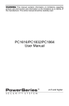
6\VWHP 6HWWLQJ &KHFNOLVW
Important! Keep this information in a secured location.
Panic Alarms:
[1] & [3] Police or _________
Silent
Audible
Disabled
Is this system partitioned?
[4] & [6] Aux. or __________
Silent
Audible
Disabled
=RQH 'HVFULSWLRQ
Zone # & Description
24Hr.
Yes
No
System
A
B
Bypass
Enabled
Home
Enabled
#1
#2:
#3:
#4:
#5:
#6:
#7:
#8:
#9:
#10
$FFHVV &RGHV
For security reasons, write only the user's name and not his/her
access code!
6SHFLDO .H\V )XQFWLRQ
[QUICK] one-key “regular” arming is activated
[HOME] one-key “home” or “system A” arming is activated
Audible Disabled
[7] & [9] Fire or ___________ Silent
The programmable output activates ___________________ when
the following occurs___________________________
System Timers
Entering and exiting your premises is permitted through doors that
you and your installer have determined. You have one exit delay
time and up to two individual entry delay times (i.e. Entry Delay 1 =
Zone 1 = Front Door = 30 sec, Entry Delay 2 = Zone 7 = Garage
Door = 90 sec).
Exit Delay = _______sec. = time allowed to exit premises before
system arms after entering access code
Entry Delay 1 = _______sec. = time allowed to disarm system
before alarm generation; enter through zone #_____
Entry Delay 2 = _______sec. = time allowed to disarm system
before alarm generation; enter through zone #_____
Alarm generation will sound siren or bell for ______ minutes.
Other Information
Alarm system installed on:_________By:________________
Service provided by:_____________Tel:________________
Your monitoring station's phone number is:______________
Your account number is:_____________________________
Alarm transformer location:_______ and is on circuit #:_____
:$55$17<
Visonic Ltd. and/or its subsidiaries and its affiliates ("the Manufacturer") warrants its
products hereinafter referred to as "the Product" or "Products" to be in conformance with
its own plans and specifications and to be free of defects in materials and workmanship
under normal use and service for a period of twelve months from the date of shipment by
the Manufacturer. The Manufacturer's obligations shall be limited within the warranty
period, at its option, to repair or replace the product or any part thereof. The Manufacturer
shall not be responsible for dismantling and/or reinstallation charges. To exercise the
warranty the product must be returned to the Manufacturer freight prepaid and insured.
This warranty does not apply in the following cases: improper installation, misuse,
failure to follow installation and operating instructions, alteration, abuse, accident or
tampering, and repair by anyone other than the Manufacturer.
This warranty is exclusive and expressly in lieu of all other warranties, obligations or
liabilities, whether written, oral, express or implied, including any warranty of
merchantability or fitness for a particular purpose, or otherwise. In no case shall the
Manufacturer be liable to anyone for any consequential or incidental damages for breach
of this warranty or any other warranties whatsoever, as aforesaid.
This warranty shall not be modified, varied or extended, and the Manufacturer does not
authorize any person to act on its behalf in the modification, variation or extension of this
warranty. This warranty shall apply to the Product only. All products, accessories or
attachments of others used in conjunction with the Product, including batteries, shall be
covered solely by their own warranty, if any. The Manufacturer shall not be liable for any
damage or loss whatsoever, whether directly, indirectly, incidentally, consequentially or
otherwise, caused by the malfunction of the Product due to products, accessories, or
attachments of others, including batteries, used in conjunction with the Products.
The Manufacturer does not represent that its Product may not be compromised and/or
circumvented, or that the Product will prevent any death, personal and/or bodily injury
and/or damage to property resulting from burglary, robbery, fire or otherwise, or that the
Product will in all cases provide adequate warning or protection. User understands that a
properly installed and maintained alarm may only reduce the risk of events such as
burglary, robbery, and fire without warning, but it is not insurance or a guarantee that
such will not occur or that there will be no death, personal damage and/or damage to
property as a result.
The Manufacturer shall have no liability for any death, personal and/or bodily injury
and/or damage to property or other loss whether direct, indirect, incidental,
consequential or otherwise, based on a claim that the Product failed to function.
However, if the Manufacturer is held liable, whether directly or indirectly, for any loss or
damage arising under this limited warranty or otherwise, regardless of cause or origin,
the Manufacturer's maximum liability shall not in any case exceed the purchase price of
the Product, which shall be fixed as liquidated damages and not as a penalty, and shall
be the complete and exclusive remedy against the Manufacturer.
Warning: The user should follow the installation and operation instructions and among
other things test the Product and the whole system at least once a week. For various
reasons, including, but not limited to, changes in environmental conditions, electric or
electronic disruptions and tampering, the Product may not perform as expected. The
user is advised to take all necessary precautions for his /her safety and the protection of
his/her property.
6/91
VISONIC LTD. (ISRAEL): P.O.B 22020 TEL-AVIV 61220 ISRAEL. PHONE: (972-3) 645-6789, FAX: (972-3) 645-6788
VISONIC INC. (U.S.A.): 10 NORTHWOOD DRIVE, BLOOMFIELD CT. 06002-1911. PHONE: (860) 243-0833, (800) 223-0020 FAX: (860) 242-8094
VISONIC LTD. (UK): UNIT 1, STRATTON PARK, DUNTON LANE, BIGGLESWADE, BEDS. SG18 8QS. PHONE: (01767) 600857 FAX: (01767) 601098
VISONIC LTD. 1998 KP-601 DE5303U (REV. 0 8/98)
6
DE5303
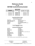
APPENDIX
Users Codes And Arming Priorities
Name
Code
Arming Priorities
Reg Home/A Away/B Byp
Master 00
User 01
User 02
User 03
User 04
User 05
User 06
User 07
User 08
User 09
User 10
User 11
User 12
User 13
User 14
User 15
User 16
User 17
User 18
User 19
User 20
User 21
User 22
User 23
User 24
User 25
User 26
User 27
User 28
User 29
User 30
User 31
User 32
User 33
User 34
User 35
User 36
User 37
User 38
User 39
User 40
User 41
User 42
User 43
User 44
User 45
User 46
User 47
User 48
D5303
7