1
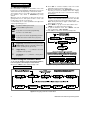
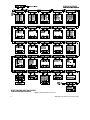
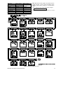
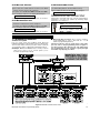
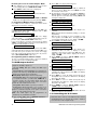
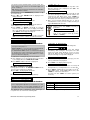
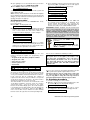
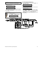
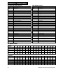
POWERMAX Fully Supervised Wireless Alarm Control System Programming Guide TABLE OF CONTENTS 1. INTRODUCTION .............................................................2 1.1 General Guidance..................................................2 1.2 Accessing the Installer’s Menu ..............................2 2. SETTING A NEW INSTALLER CODE..........................3 3. ENROLLING WIRELESS DEVICES AND KEYFOBs ..3 3.1 General Guidance..................................................3 3.2 Wireless Devices ...................................................3 3.3 Keyfob Transmitters...............................................3 3.4 Deleting Device and Keyfob IDs ............................4 4. DEFINING ZONE TYPES ..............................................5 4.1 Preliminary Guidance ............................................5 4.2 Zone Definition Procedure .....................................5 5. DEFINING CONTROL PANEL PARAMETERS ...........7 5.1 Preliminary Guidance ............................................7 5.2 Entry Delays...........................................................7 5.3 Exit Delay ...............................................................7 5.4 Bell Time ................................................................7 5.5 Abort Time .............................................................7 5.6 Alarm Cancel Time ................................................7 5.7 Quick Arming .........................................................9 5.8 Bypass ...................................................................9 5.9 Restart Exit ............................................................9 5.10 Piezo Beeps.........................................................9 5.11 Trouble Beeps .....................................................9 5.12 Panic Alarm .........................................................9 5.13 Swinger Stop .......................................................9 5.14 Cross Zoning .......................................................9 5.15 Supervision Interval .............................................9 5.16 AUX Button ........................................................10 5.17 Jamming Detection ............................................10 5.18 Two-Way Voice - Private Telephones ...............10 5.19 Two-Way Voice - Central Stations ....................10 5.20 PGM / X-10 Time ...............................................10 5.21 Lighting Lockout Time .......................................10 5.22 Latchkey Arming ................................................10 5.23 “Not Active” Time ...............................................10 5.24 Back Lighting .....................................................10 5.25 Duress Alarm (ambush) ....................................11 5.26 Piezo Siren ........................................................11 6. DEFINING COMMUNICATION PARAMETERS .........11 6.1 Preliminary Guidance ..........................................11 6.2 Dialing Method..................................................... 12 6.3 Phone Line Test Interval ..................................... 12 6.4 First Central Station Telephone .......................... 12 6.5 First Account No. ................................................. 12 6.6 Second Central Station Telephone ..................... 12 6.7 Second Account No............................................. 12 6.8 Report Format ..................................................... 12 6.9 4/2 Pulse Rate ..................................................... 12 6.10 Reporting to Central Stations ............................ 12 6.11 Dialing Attempts ................................................ 14 6.12 First Private Telephone No. .............................. 14 6.13 Second Private Telephone No. ......................... 14 6.14 Third Private Telephone No. ............................. 14 6.15 Telephone Message Type ................................. 14 6.16 Private Tel. Dialing Attempts ............................. 14 6.17 Reporting to Private Telephones....................... 14 6.18 Telephone Acknowledge ................................... 14 6.19 Pager Telephone Number ................................. 14 6.20 Pager’s PIN No. ................................................. 14 6.21 Reporting to a Pager ......................................... 14 6.22 Recent Closure .................................................. 15 6.23 Remote Access ................................................. 15 6.24 Downloader Code .............................................. 15 7. DEFINING OUTPUT PARAMETERS ......................... 15 7.1 Preliminary Guidance .......................................... 15 7.2 PGM Output Control ............................................ 16 7.3 Controlling the X-10 Units ................................... 16 8. RECORDING SPEECH ............................................... 17 8.1 Mode Description and Activation......................... 17 8.2 Recording Procedure .......................................... 17 9. DIAGNOSTIC TEST .................................................... 17 9.1 Mode Description and Activation......................... 17 9.2 Test Procedure .................................................... 18 10. USER FUNCTIONS .................................................... 18 11. READING THE EVENT LOG ..................................... 18 11.1 Event Log Description ....................................... 18 11.2 Reading Procedure ........................................... 18 11.3 Erasing the Event Log ....................................... 19 APPENDIX A. EVENT CODES ........................................ 20 APPENDIX B. PROGRAMMABLE ZONE TYPES........... 22 WARNING! The PowerMax control unit has not been investigated by UL for household fire. WARNING! All model PowerMax outputs are not power limited and shall not be used in UL-listed Systems. WARNING! Zone type "emergency" can not be used for medical applications in UL-listed systems. If you re-program a system already in use, the previous system status will be erased upon quitting the installer menu. Be sure to conduct a full walk test, including all windows and doors, to allow re-capture of the system status. DE5450P PowerMax Programming Guide 1 1. INTRODUCTION 1.1 General Guidance We recommend to program the PowerMax on the work bench before actual installation. Operating power may be obtained from the backup battery or from the AC mains. The installer’s menu is accessible only to those who know the installer’s code, which is 9999 by factory default. Obviously, you are expected to use this code only once for gaining initial access, and replace it with a secret code known only to yourself (see Section 2). You will mainly use 5 control pushbuttons throughout the entire programming process: - to advance within a given menu. - to retreat within a given menu. - to go down one level in the programming structure or to confirm data. B. Click <OK> to select the installer’s mode. The control panel will prompt you for the installer code. C. Enter the valid installer code (9999) if this is the first time you access the installer menu. The “Happy Tune” will sound if the code is correct and the display will change to: 1.NEW INSTL CODE You have now gained access to the first item on the installer menu. Detailed instructions on how to deal with each item are given in sections 2 through 10 below. Note: At this point refer to Figure 2, which takes over where Figure 1 leaves off. D. Click <NEXT> to go up in menu item numbers and <BACK> to go down in menu item numbers. E. To quit the installer’s menu, click <AWAY>. This will take you directly to “<OK> TO EXIT”. F. Click <OK> to return to the normal operating mode. - to go up one level in the programming structure. - instant return to the installer menu (top level). The sounds you will hear while programming are: - Single beep, heard whenever a key is pressed. - Double beep, indicates automatic return to the normal operating mode (by timeout). ☺ - Happy Melody (- - - –––), indicates successful completion of an operation. - Sad Melody (–––––), indicates a wrong move or rejection. 1.2 Accessing the Installer’s Menu To access the installer’s menu and navigate within it, refer to Figures 1 and 2 and proceed as follows: A. Click the <NEXT> button until the display reads: INSTALLER Figure 1. Gaining Access to the Installer’s Menu MODE Figure 2. Navigating within the Installer Menu 2 DE5450P PowerMax Programming Guide 2. SETTING A NEW INSTALLER CODE A. Having successfully gained access to the installer menu (see Section 1), the display will read: 1.NEW INSTL CODE B. To change the installer code, click <OK>. The old code will appear (the factory default if this is the first change): INST. CODE 9999 The cursor will flash on the first digit of the code. C. Enter a new 4-digit code. After entering the 4th digit, the cursor will stop flashing. Attention! Do not use “0000” - this code is invalid. D. Click <OK>. The “Happy Tune” will sound and the display will revert to: 1.NEW INSTL CODE E. You may now click <NEXT> or <BACK> to select any other item on the installer’s menu. 3. ENROLLING WIRELESS DEVICES AND KEYFOB TRANSMITTERS 3.1 General Guidance The ENROLLING mode has two sub-modes: • ENROLL WL DEVICE (wireless devices) • ENROLL KEYFOB (multi-button CodeSecure transmitters). Refer to Paragraphs 3.2 and 3.3 for enrolling procedures. Attention! CodeSecure transmitters are mainly used for arming/disarming and can not be enrolled to zones. For enrolling to zones, use only non-CodeSecure wireless devices. 3.2 Wireless Devices Wireless devices include various wireless PowerCode detectors and hand-held special-task transmitters. Your control panel must recognize the unique identification code (ID) of each such device in order to supervise them, receive their signals and respond accordingly. Before anything else, gather all the devices that you intend to enroll, and make sure they all have batteries installed. • The lens at the front of PIR and dualtechnology sensors should be masked to prevent inadvertent transmission. • Use rubber bands to bind magnetic contact transmitters together with their magnets, to prevent them from sending out alarm transmissions. To enroll wireless devices, go through the following steps: A. Upon gaining access to the installer menu (see Section 1), the display will read “1. NEW INSTL CODE”. B. Click <NEXT>. The enrolling mode will be selected and the display will show: STOP 2. ENROLLING C. Click <OK> to select the “enroll wireless devices” submode. The display will change to: ENROLL WL DEVICE D. Click <OK> again. The display will read: Zone No : _ _ E. Suppose that the wireless device you are about to enroll is to be installed in Zone No. 4. Assuming that zone No. 4 is free - no device has yet been enrolled to it - just enter <0><4>. The display will change to: Zone No: 04 The clear space at the far right tells you that the zone is free - no wireless device has been enrolled to it as yet. F. Click <OK>. The display will prompt you to initiate a transmission from the chosen wireless device: DE5450P PowerMax Programming Guide TRANSMIT NOW G. Initiate transmission from the chosen device by: • Removing the mask from the lens of the PIR motion detector, or • Separating the magnet from the magnetic contact sensor, or • Pressing the button of the hand-held miniature transmitter, or • Pressing the test button of the smoke detector. H. In response to the transmitted signal, the “Happy Tune” (- - - ––– ) will sound and the display will change to: Zone No: 04 A dark box will appear at the far right, indicating that the chosen device has been enrolled to Zone No. 4. Note: If the same device is already enrolled to another zone, the “Happy Tune” will sound twice in succession. I. From this point on, you may continue in several different directions: • If you wish to enroll another device to another zone, select the other zone by: - Clicking <NEXT> to go up (567.....) - Clicking <BACK> to go down (321.....) - Clicking <HOME> <desired zone #>. After that, proceed as in the example above. • To delete a device ID, refer to Para. 3.4. • To select the Enroll Keyfob sub-mode, click <HOME> and then <NEXT>. • To return to the main menu, click <AWAY>. This will bring back the display: <OK> TO EXIT You may now review and select any other mode on the installer’s menu (by clicking <NEXT> or <BACK>). 3.3 Keyfob Transmitters Keyfob transmitters are multi-button wireless units of the CodeSecure™ type. Eight system users carry them on their person to exercise better, quicker and safer control over various system functions. Your control panel must recognize the unique identification code (ID) of each such keyfob in order to respond to commands transmitted by them. Note: For UL installations where the model MCT-234 keyfob is used, the voice/speaker on the PowerMax shall be enabled. 3 Before anything else, gather up all keyfob units you intend to enroll, and make sure they all have batteries installed. Keyfob transmitter enrolling involves the following steps: A. Perform Steps A through C in Para. 3.2 above, until the display reads: ENROLL WL DEVICE B. Click <NEXT>. The display will read: ENROLL KEYFOB No: _ No: 5 No. 15 Keyfob No. 8 <OFF> to delete C. Click <OFF>. The display will change to: Zone No. 15 or, in the other case: The clear space at the far right tells you that the memory location is free. E. Click <OK>. The display will prompt you to initiate a transmission from the chosen keyfob: TRANSMIT Zone B. Click <OK>. The display will change to: D. Suppose that the Keyfob you are about to enroll is to be designated as Keyfob No. 5. Assuming that memory location No. 5 is free - no keyfob has yet been enrolled to it - click the <5> key. The display will change to: Keyfob Occupied zones or keyfob memory locations must be cleared (enrolled ID must be deleted) before enrolling a new ID. To delete an existing ID, proceed as follows: A. Select the desired zone or memory location. If, for example you selected Zone No. 15, or keyfob No. 8, the display will read: or, in the other case: C. Click <OK>. The display will read: Keyfob 3.4 Deleting Device and Keyfob IDs NOW Keyfob No. 8 Note that the dark box at the far right has disappeared. It is now possible to enroll a new ID. It is also possible to leave the cleared zone or memory location free, and return to the main menu. F. Initiate a transmission from the chosen keyfob by pressing any one of its pushbuttons. In response, the “Happy Tune” (- - - –––) will sound and the display will change to: Keyfob No: 5 A dark box will appear at the far right, indicating that the chosen Keyfob has been enrolled as Keyfob No. 5. Note: If the same keyfob is already enrolled elsewhere, the “Happy Tune” will sound twice in succession. G. From this point on, you may continue in several different directions: • If you wish to enroll another keyfob, select the desired number by: - Clicking <NEXT> to go up (678.....) - Clicking <BACK> to go down (432.....) - Clicking <HOME> <keyfob #>. After that, proceed as in the example above. • To delete keyfob IDs, refer to Para. 3.4. • To return to the main menu, click <AWAY>. This will bring back the display: <OK> TO EXIT You may now review and select any other mode on the installer’s menu (by clicking <NEXT> or <BACK>). 4 DE5450P PowerMax Programming Guide 4. DEFINING ZONE TYPES 4.1 Preliminary Guidance 3. This mode allows you to attribute one of 9 zone types to any one of the 29 wireless zones offered by the PowerMax. In addition, it allows you to assign a name to each zone and determine whether the zone will operate as a chime zone while the system is in the disarmed state. A list of factory defaults is printed on the following page. You may fill out the blank columns even before you start and proceed to program according to your own list. To reach the DEFINE ZONES mode, proceed as follows: A. Upon gaining access to the installer menu (see Section 1), the display will read “1. NEW INSTL CODE”. B. Click <NEXT> twice. The 3rd mode will be selected: DEFINE ZONES Should you wish to get an overall view of the entire zone definition process, refer to Figure 3. You may even use the chart as your only guide along the programming process, instead of going through the written step-by-step procedure. Remember! 1. A delay zone is also a perimeter zone by definition. 2. When arming "AWAY", all interior zones become follower zones during the exit and entry delays. Zone types are fully explained in Appendix B at the end of this programming guide. ZONE NAME LIST Attic Back door Basement Bathroom Bedroom Child room Closet Den Dining room Downstairs Emergency Fire Front door Garage Garage Door Guest room Hall Kitchen Laundry room Living room Master bath Master Bdrm Office Upstairs Utility room Yard Custom 1 Custom 2 Custom 3 Figure 3. DEFINE ZONES Flow Chart 4.2 Zone Definition Procedure Once “3. DEFINE ZONES” is viewed, proceed as follows: A. Click <OK>. The display will read: Zone No. __ B. Suppose that you wish to define (or re-define) Zone No. 7. All you have to do is select the zone by entering <0><7>, thereby changing the display to: Zone No. 07 If there is no dark box at the far right, the zone has not learned a device ID as yet. If there is a dark box, the zone is already linked to a specific wireless device. DE5450P PowerMax Programming Guide C. Click <OK>. The display will read: Z07: TYPE _ D. You can now enter the number of a specific zone definition (see list in Figure 3) and click <OK>. If, for example, you enter <5><OK>, the display will read: 5.24h silent Note: If you click <OK> without entering a number, the display will show the current definition of the selected zone, with a dark box at the far right. You may then review all definitions by clicking <NEXT> repeatedly. E. To accept the definition on display, click <OK>. A dark box will appear at the far right: 5 5.24h silent chime F. Click <OK> once more to confirm. The “Happy Tune” will sound, and your selection will be memorized. The display will then change to: Z07:NAME _ G. At this point, enter the serial number of the zone name you wish to attach to zone No. 7 from the list of 29 available names (see list in Figure 3). Note: If you click <OK> without entering a number, the display will show the current name of the selected zone, with a dark box at the far right. You may then review all names by clicking <NEXT> repeatedly. H. If you enter a number (say 13), the display will read: Front on or: chime off You can toggle the display between CHIME ON and CHIME OFF by clicking <NEXT>. K. Click <OK> once if you approve the already selected option - the “Happy Tune” will sound. Alternatively, click <OK> twice while the other option is viewed. The “Happy Tune” will sound and the display will revert to: Zone No. 07 L. From this point on, you may continue in several different directions: - Click <NEXT> to go up (8910.....) - Click <BACK> to go down (654.....) Repeat Steps C through K above for all other zones that you plan to use. • To return to the main menu, click <AWAY>. This will get you back to: door I. Click <OK> to accept this name - a dark box will appear at the far right. Click <OK> again to confirm. The “Happy Tune” will sound, your selection will be saved and the display will change to: <OK> Z07:CHIME TO EXIT You may now review and select any other mode on the installer’s menu (by clicking <NEXT> or <BACK>). J. Click <OK>. You are about to determine whether this zone will be a chime zone or not. The display will read: DEFAULT AND PROGRAMMED ZONE DEFINITIONS Zone Type Zone No. Default 1 2 3 4 5 6 7 8 9 10 11 12 13 14 15 16 17 18 19 20 21 22 23 24 25 26 27 28 29 30 Delay 1 Delay 1 Delay 2 Perimeter Perimeter Interior Interior Perimeter Perimeter Perimeter Interior Interior Perimeter Perimeter Interior Perimeter Perimeter Perimeter Perimeter Fire Fire Emergency Emergency 24 h / silent 24 h / silent 24 h / audible 24 h / audible non-alarm non-alarm non-alarm Programmed Zone Name Default Programmed Chime Y/N? * Front door Garage Garage door Back door Child room Office Dining room Dining room Kitchen Living Room Living Room Bedroom Bedroom Guest Room Master Bedroom Master Bedroom Laundry room Master Bathroom Basement Fire Fire Emergency Emergency Basement Office Attic Den Yard Hall Utility room * Note: All zones are non-chime by default. Enter your own choice in the last column and program accordingly. 6 DE5450P PowerMax Programming Guide 5. DEFINING CONTROL PANEL PARAMETERS 5.1 Preliminary Guidance A. Mode description This mode allows you to customize the control panel and adapt its characteristics and behavior to the requirements of the particular user. Should you wish to obtain an overall view of the entire programming process, refer to the programming chart in Figure 4. You may even use the chart as your only guide along the programming process, instead of going through the written step-by-step procedure. B. Gaining access to the “Define Panel” Memory Locations To reach the DEFINE PANEL mode, proceed as follows: Upon gaining access to the installer menu (see Section 1), the display will read “1. NEW INSTL CODE”. Click <NEXT> until the 4th mode is displayed: 4. DEFINE PANEL Click <OK>. The first memory location will be selected and displayed: 01:ENTRY DELAY 1 Click <NEXT> or <BACK> until you reach the memory location you wish to access (see rectangles 01 to 26 in Figure 4). C. Programming Method The ”multiple choice” programming method is applied here. Once a memory location is selected, its number and name are displayed as shown in the following example: 03:EXIT DELAY When you click <OK>, the currently saved option will be displayed with a dark selection box at the far right of the display: exit delay 45s If you approve of this option, click <OK>. The “Happy Tune” will sound and the display will revert to the number and name of the presently selected memory location. If you do not approve, review the other options by clicking <NEXT> or <BACK> repeatedly. Options that are not saved will have a clear space at the far right, as shown: exit delay 90s To select an option, click <OK>. A dark box will appear at the far right of the display. Clicking <OK> once more will cause your selection to be saved - the “Happy tune” will sound and the number and name of the presently selected memory location will be re-displayed. Click <NEXT> or <BACK> to select another memory location. Locations No. 1 (entry delay 1) and 2 (entry delay 2) allow you to program the length of these delays. Available options for each delay are: 00, 15, 30, 45, 60, 180 and 240 seconds. In UL installations, these delays must be 45 s max. Upon selecting Location No. 01, the display will read: 01:ENTRY DELAY 1 Select the desired option as outlined in Para. 5.1 C above. When done, Click <NEXT> to select Location No. 2. Continue the same way as in location 1. When done, Click <NEXT> to select Location 3. 5.3 Exit Delay An exit delay allows the user to arm the system and leave the protected site via specific routes and doors without causing an alarm. Slow-rate warning beeps will start sounding once the arming command has been given. This will continue until the last 10 seconds of the delay, throughout which the beeping rate will increase. Location No. 3 allows you to program the length of the exit delay. Available options are: 30, 60, 90, 120, 180 and 240 seconds. Upon selecting Location 03, the display will read: 03:EXIT DELAY Select the desired option as outlined in Para. 5.1 C above. 5.4 Bell Time Here you select the length of time the bell (or siren) is allowed to function upon alarm. The bell time starts upon activation of the siren. Once the bell time expires, the siren is automatically shut down. Available options: 01, 04, 08, 10, 15 and 20 minutes. In UL installations, set bell time to 4 minutes minimum. Upon selecting Location 04, the display will change to: 04:BELL TIME Select the desired option as outlined in Para. 5.1 C above. 5.5 Abort Time Here you select the length of time allowed by the system to abort an alarm. The PowerMax is programmed to provide an “abort interval” that starts upon detection of an alarm. During this interval, the buzzer sounds a warning but the siren remains inactive and the alarm is not reported. If the user disarms the system within the allowed abort interval, the alarm will be aborted. Available options: 00, 15, 30, 45, 60, 180, 240 seconds. Upon selecting Location 05, the display will change to: 05:ABORT TIME 5.2 Entry Delays Select the desired option as outlined in Para. 5.1 C above. Two different entry delays allow the user to enter the protected site (while the system is in the armed state) via 2 specific doors and routes without causing an alarm. Following entry, the user must disarm the control panel before the entry delay expires. Slow-rate warning beeps will start sounding once the door is opened. This will continue until the last 10 seconds of the delay, throughout which the beeping rate will increase. 5.6 Alarm Cancel Time DE5450P PowerMax Programming Guide Here you determine the ”cancel alarm” period that starts upon reporting an alarm to the central station. If the user disarms the system within that time period, a “cancel alarm” message will be sent to the central station. The options are: 1, 5, 15, 60 minutes, 4 hours and also cancel inactive. 7 Figure 4. DEFINE PANEL Flow Chart 8 DE5450P PowerMax Programming Guide Upon selecting Location 06, the display will change to: 06:ALARM CANCEL 11:TROUBLE BEEPS Select the desired option as outlined in Para. 5.1 C above. Select the desired option as outlined in Para. 5.1 C above. 5.12 Panic Alarm 5.7 Quick Arming Here you determine whether the user will be allowed to initiate a panic alarm by simultaneous pressing of the two panic buttons (on the keypad) or away + home (on a keyfob transmitter). The two options are: enable panic and disable panic. Here you determine whether the user will be allowed to perform quick arming or not. Once quick arming is permitted, the control panel does not request a user code before it actually arms the system. The two options are: quick arm on and quick arm off. Upon selecting Location 07, the display will change to: 07:QUICK ARM Select the desired option as outlined in Para. 5.1 C above. 5.8 Bypass Here you permit either manual bypassing of individual zones (through the USER SETTINGS menu), or allow the system to "force arm" (perform automatic bypassing) of zones that are open throughout the exit delay. If a zone is open and forced arming is not permitted, “NOT READY” will be displayed and the system will not arm (the “Sad Melody” will sound). If "no bypass" is selected, neither manual bypassing nor force arming will be allowed. Options: manual bypass, force arm and no bypass. In UL installations, "force arm" must not be selected. Upon selecting Location 08, the display will change to: 08:BYPASS Select the desired option as outlined in Para. 5.1 C above. 5.9 Restart Exit Here you determine whether the exit delay will restart if the exit / entry door is reopened before the exit delay expires. Restarting the exit delay is helpful if the user reenters immediately after going out to retrieve an item that he left behind. The two options are: restart ON and restart OFF. In UL installations, "restart OFF" must be selected. Upon selecting Location 09, the display will change to: 09:RESTART EXIT Select the desired option as outlined in Para. 5.1 C above. 5.10 Piezo Beeps Here you determine whether warning beeps will sound or will be muted throughout the exit and entry delays. An additional option is to mute the warning beeps only when the system is armed “HOME”. Three options are available: enable beeps, off when home and disable beeps. Upon selecting Location 10, the display will change to: 10:PIEZO BEEPS Select the desired option as outlined in Para. 5.1 C above. 5.11 Trouble Beeps Under trouble conditions, the sounder emits a series of 3 short beeps once per minute. Here you determine whether this special beeping sequence will be active, inactive, or just inactive at night (the range of “night” hours is defined in the factory). The 3 options are: enable beeps, off at night (8 PM through 7 AM) and disable beeps. Upon selecting Location 12, the display will change to: 12:PANIC ALARM Select the desired option as outlined in Para. 5.1 C above. 5.13 Swinger Stop Here you determine how many times each zone is allowed to initiate an alarm within a single arming period. If the number of alarms from a specific zone exceeds the number programmed in this location, the control panel will automatically bypass the zone to prevent recurrent siren noise and nuisance reporting to the central station. The zone will be reactivated upon disarming, or 24 hours after having been bypassed (if the system remains armed). The available options are: shut after 1, shut after 2, shut after 3 and no shutdown. In UL installations, No Shutdown must be selected. Upon selecting Location 13, the display will change to: 13:SWINGER STOP Select the desired option as outlined in Para. 5.1 C above. 5.14 Cross Zoning Here you determine whether cross zoning will be active or inactive. Cross zoning is a method used to counteract false alarms - an alarm will not be initiated unless two adjacent zones are violated within a 30-second time limit. This feature is active only when arming AWAY and only with zone couples from zone No. 20 up (20 and 21, 22 and 23, etc.). You may use any one of these zone couples to create a “cross-zoned” area. Note: If one of two crossed zones is bypassed (see Para. 5.8), the remaining zone will function independently. The options are: cross zone ON and cross zone OFF. Per UL, cross zoning is not recommended on Entry/ Exit zones. Upon selecting Location 14, the display will change to: 14:CROSS ZONING Select the desired option as outlined in Para. 5.1 C above. 5.15 Supervision Interval Here you determine the time limit for reception of supervision reports from supervised wireless devices. If any device does not report at least once within the selected time limit, an “INACTIVITY” alert will be initiated. The options are: 1, 2, 4, 8, 12 hours and disable. In UL installations, the interval must not exceed 4 h and shall not be disabled. Upon selecting Location 15, the display will change to: 15:SUPERVISION Select the desired option as outlined in Para. 5.1 C above. Upon selecting Location 11, the display will change to: DE5450P PowerMax Programming Guide 9 5.16 AUX Button Here you select the function of the AUX button on keyfob transmitters. Three options are offered: Status: Pressing the AUX button will cause the control panel’s voice module to announce the system status. Instant: Pressing the AUX button while the exit delay is in progress will cause the system to arm “instant”, (the entry delay is canceled). PGM / X-10: Pressing the AUX button will activate the PGM output or X-10 units (see further programming under “DEFINE OUTPUTS”). Upon selecting Location 16, the display will change to: 16:AUX BUTTON Select the desired option as outlined in Para. 5.1 C above. 5.17 Jamming Detection Here you determine whether jamming (interfering transmissions) on the radio channel used by the system will be detected and reported or not. The options are: jam detect ON and jam detect OFF. If the jam detect ON option is selected, the system will not allow arming under jamming conditions. Upon selecting Location 17, the display will change to: 17:JAM DETECT Select the desired option as outlined in Para. 5.1 C above. 5.18 Two-Way Voice - Private Phones Here you determine whether two-way voice communication with private telephones will be allowed or not. The two options are: enable 2-way and disable 2-way. In UL installations, this function must be disabled. Upon selecting Location 18, the display will change to: 18:VOICE PRVT Select the desired option as outlined in Para. 5.1 C above. 5.19 Two-Way Voice - Central Stations Here you select the timeout for two-way voice communication with Central Stations. The options are: 10, 45, 60, 90 seconds, 2 minutes and disable (no two-way voice communication). controlled by sensors will be off, even when the associated sensors are triggered. Sensors (zones) can be programmed to control lighting devices via the X-10 and PGM outputs - see Section 7 for details. In UL installations, this function shall not be used. Upon selecting Location 21, the display will change to: 21:LOCKOUT TIME A. Click <OK>. The display will read: start- HH:MM A B. Click <OK>. The display will change to: start- 00:00 A C. Enter the time at which you wish the lockout state to begin (usually at dawn). Note: AM and PM are selected by clicking “ς” and “#“, respectively. Once the viewed time is correct, regardless of the cursor position, click <OK> twice. The display will change to: stop- HH:MM P D. Click <OK>. The display will change to: stop- 00:00 P E. Enter the time at which you wish the lockout state to end (usually at dusk). With the correct time on display, regardless of the cursor position, click <OK> twice. The display will revert to “stop - HH:MM P”. F. Click <HOME> to return to “21: LOCKOUT TIME”. 5.22 Latchkey Arming Here you determine whether the system can be armed in the latchkey mode. If the system is armed this way, a “latchkey” message will be sent to specific telephones upon disarming by a “latchkey user” (users 5 through 8 or keyfob transmitters 5 through 8). This mode is useful when parents at work want to be informed of a child’s return from school. The options are: Latchkey ON and Latchkey OFF. Upon selecting Location 22, the display will change to: 22:LATCHKEY In UL installations, this function must be disabled. Select the desired option as outlined in Para. 5.1 C above. In UL installations, this function shall not be used. Upon selecting Location 19, the display will change to: 5.23 “Not Active” Time 19:VOICE C.S. Select the desired option as outlined in Para. 5.1 C above. 5.20 PGM / X-10 Time Here you determine the pulse duration (length of activation time) for the PGM output and the X-10 units. The available options are: 2 s, 30 s, 2 min, 4 min and toggle. “Toggle” means that one command will activate the output and the following command will deactivate it. Upon selecting Location 20, the display will change to: 20:PGM/X-10 TIME Select the desired option as outlined in Para. 5.1 C above. In UL installations, this function shall not be used. 5.21 Lighting Lockout Time This memory location is different from the others, because here you do not select one of several options. Here you set daytime limits between which lighting devices 10 Here you determine the time limit for reception of signals from sensors used to monitor the activity of sick, elderly or disabled people. If no device detects and reports movement at least once within the defined time limit, a “not-active” alert will be initiated. The options are: 3, 6, 12, 24, 48, 72 hours and canceled. Upon selecting Location 23, the display will change to: 23:NOT ACTIVE Select the desired option as outlined in Para. 5.1 C above. 5.24 Back Lighting Here you determine whether the back lighting of the keypad will remain on at all times or will come on when a key is pressed, then go off within 10 seconds if no further keystrokes are sensed. The two options are: always on and off after 10 s. In UL installations, “off after 10 s” must be selected to save battery power. DE5450P PowerMax Programming Guide Upon selecting Location 24, the display will change to: 24:BACK LIGHT Select the desired option as outlined in Para. 5.1 C above. 5.25 Duress Alarm (ambush) A duress message can be sent to the central station if the user is forced to disarm the system under violence or menace. To initiate a duress message, the user must disarm the system with the duress code (2580 by default). Here you can change the code digits or enter "0000" to deactivate the duress feature. The system does not allow the user to program the duress code saved in this memory location as a regular user code. Note: It is not recommended to use 1234 or 1 number off. Upon selecting Location 25, the display will change to: 5.26 Piezo Siren Here you determine whether the piezo siren built into the control cabinet will sound or not upon alarm. Ask the user whether he prefers it to sound or to be silent. The two options are: piezo siren on and piezo siren off. In UL installations, the piezo siren must be ON. Upon selecting Location 26, the display will change to: 26:PIEZO SIREN Select the desired option as outlined in Para. 5.1 C above. Having thus completed a full cycle of all 26 panel attributes, you may now continue by programming the communication parameters (see Section 6), or you may select any other item on the installer’s menu (see opposite column). If at this point you wish to return to the installer’s menu, click <AWAY>. This will get you back to: 25:DURESS Click <OK>. The display will show "duress code 2580", with the cursor on the first digit. Press <OK> to accept this or key in another code and press <HOME> to exit. <OK> TO EXIT You may now review and select any other mode on the installer’s menu (by clicking <NEXT> or <BACK>). 6. DEFINING COMMUNICATION PARAMETERS 6.1 Preliminary Guidance A. Mode description This mode allows you to adapt the telephone communication parameters to the local requirements. Note: For all UL-certified systems, it is up to the installer to completely verify the compatibility between the DACT format and the receivers. Compatible central station receivers: – Osborne-Hoffman model 2000 – Ademco Model 685 – FBII Model CP220 – Radionics Model D6500 – Sur-Gard Model SG-MLR2-DG – Silent Knight Model 9500 There are two kinds of memory locations in this sub-mode, each of which requires a different programming method: Multiple Choice Locations: these memory locations allow you to choose one of several options (see C below for programming procedure) Numerical Data Locations: these memory locations accept a sequence of digits (phone number, account number etc. - see D below for programming procedure). Should you wish to obtain an overall view of the entire process, refer to the programming chart in Figure 5. You may even use the chart as your only guide along the programming process, instead of going through the written step-by-step procedure. B. Accessing the “Define Comm” Memory Locations Upon gaining access to the installer menu (see Section 1), the display will read “1. NEW INSTL CODE”. Click <NEXT> until the 5th mode is displayed: 5. DEFINE COMM. Click <OK>. The first memory location will be selected and displayed: 01: DIAL METHOD DE5450P PowerMax Programming Guide Click <NEXT> or <BACK> until you reach the memory location you wish to access (see rectangles 01 to 23 in Figure 5). C. Programming Multiple Choice Locations When a multiple choice location is selected, its number and name will be displayed as shown in this example: 07:REPORT FORMAT When you click <OK>, the currently saved option will be displayed with a dark selection box at the far right: SIA If you approve of this option, click <OK>. The “Happy Tune” will sound and the number and name of the present memory location will be re-displayed. If you do not approve, review the other options by clicking <NEXT> or <BACK> repeatedly. Options that are not saved will have a clear space at the far right, as shown: contact ID To select an option that is not the currently saved one, click <OK>. A dark box will appear at the far right. Clicking <OK> once more will cause your selection to be saved the “Happy tune” will sound and the number and name of the present memory location will be re-displayed. D. Programming Numerical Data Locations When a numeric data location is selected, its number and name will be displayed as shown in this example: 03:1ST CNTR TEL When you click <OK>, the currently saved number will be displayed, with a blinking cursor under the leftmost digit (if there is no number programmed, the display will be blank). 073849204 If you approve of the saved number, click <OK>. The “Happy Tune” will sound and the number as well as the name of the present memory location will be re-displayed. If you do not approve, enter the new number (up to 16 digits). To erase undesired digits to the right of the cursor, click <OFF>. 11 With the correct number on display and the blinking cursor to the right of the last digit, click <OK>. The cursor will disappear. Click <OK> once more. The new number will be saved the “Happy tune” will sound and the number + name of the present memory location will be re-displayed. IMPORTANT: In telephone / pager number locations and account number locations, you may be required to enter hexadecimal digits. In telephone number locations, these digits are used as codes to control the dialer: Hex. Keying Code Digit Sequence Significance A <#> ⇒ <0> Dialer waits 5 seconds or waits for dial tone, whichever comes first and then dials. B <#> ⇒ <1> Inserts an asterisk (ς) C <#> ⇒ <2> Inserts a pound sign (#) E <#> ⇒ <3> Dialer waits 5 seconds for dial tone and goes on hook if none is received. <#> ⇒ <4> Not applicable in phone numbers F <#> ⇒ <5> Not applicable in phone numbers D When entering a series of digits, the following keys are useful: <Numeric keypad> - to enter the number - moves the cursor from left to right - moves the cursor from right to left - deletes everything after the cursor (to the right). 6.2 Dialing Method Here you determine the dialing method used by the automatic dialer built into the PowerMax control panel. The options are: Pulse and DTMF Upon selecting Location 01, the display will read: 01:DIAL 6.3 Phone Line Test Interval Here you determine the time interval between consecutive test messages sent to the central station. The control panel does it at regular intervals to verify proper communication. However, be advised that the first test will take place 12 hours after you exit the installer mode. The options are: test every 1, 5, 7, 30 days and test off. Upon selecting Location 02, the display will change to: TEST Select the desired option as outlined in Para. 6.1 C above. 6.4 First Central Station Telephone Here you program the telephone number of the first central station to which the PowerMax will report the event groups defined in memory location 09. Upon selecting Location 03, the display will change to: 03:1ST CNTR TEL Enter the first central station’s telephone number (16 digits max.) as outlined in Para. 6.1 D above. 12 Here you enter the account number that will identify your specific alarm control system to the 1st central station. The number consists of 4 hexadecimal digits. Upon selecting Location 04, the display will change to: 04:1ST ACCOUNT # Enter the account no. as outlined in Para. 6.1 D above. 6.6 Second Central Station Telephone Here you program the telephone number of the second central station to which the PowerMax will report the event groups defined in memory location 09. Upon selecting Location 05, the display will change to: 05:2ND CNTR TEL Enter the second central station’s telephone number as outlined in Para. 6.1 D above. 6.7 Second Account No. Here you enter the account number that will identify your specific alarm control system to the 2nd central station. The account number consists of 4 hexadecimal digits. Upon selecting Location 06, the display will change to: 06:2ND ACCOUNT # Enter the account no. as outlined in Para. 6.1 D above. 6.8 Report Format Here you select the reporting format used by the control panel to report events to central stations. The options are: Contact-ID SIA 4/2 1900/1400 4/2 1800/2300 (for code lists - see Appendix A). Upon selecting Location 07, the display will change to: 07:REPORT FORMAT Select the desired option as outlined in Para. 6.1 C above. 6.9 4/2 Pulse Rate METHOD Select the desired option as outlined in Para. 6.1 C above. 02:LINE 6.5 First Account No. Here you select the pulse rate at which data will be sent to central stations if any one of the 4/2 formats has been selected in Location 07. The options are: 10, 20, 33 and 40 pps Upon selecting Location 08, the display will change to: 08:4/2 PLS RATE Select the desired option as outlined in Para. 6.1 C above. 6.10 Reporting to Central Stations Here you determine which types of events will be reported to central stations. Due to lack of space in the display, abbreviations are used: alarm is “alrm”, alert is “alrt” and open/close is “o/c”. The asterisk (γ) is a separator between events reported to central station 1 and events reported to central station 2. Messages are divided by type into three groups: GROUP EVENTS REPORTED Alarms Fire, Burglary, Panic, Tamper Open/Close Arming AWAY, Arming HOME, Disarming Alerts No-activity, Emergency, Latchkey Group 1 has the highest priority and group 3 has the lowest priority. The selectable options are shown in the following table: DE5450P PowerMax Programming Guide Plan name Sent to center 1 Sent to center 2 all γ backup All events all –o/c γ backup All but open/close if center 1 } All does not all γ all All events All events all –o/c γ all –o/c All but open/close All but open/close all –o/c γ o/c All but open/close open/close only all (–alrt) γ alrt All but alerts Alerts alrm γ all (–alrm) Disable Alarms All but alarms Nothing Nothing Note: “All” means that all 3 groups are reported and also trouble messages - sensor / system low battery, sensor inactivity, power failure, jamming and communication failure. Upon selecting Location 09, the display will change to: 09:REPORT⇐CNTR Select the desired option as outlined in Para. 6.1 C above. Figure 5. DEFINE COMM Flow Chart DE5450P PowerMax Programming Guide 13 6.11 Dialing Attempts Here you determine how many times the communicator will dial the central station’s number. The options are: 2, 4, 8, 12, and 16 attempts. Attention! A maximum of 2 dialing attempts is permitted by the Australian Telecommunication Authority. In UL installations, dialing attempts should be set to 8. Upon selecting Location 10, the display will change to: 10:DIAL ATTEMPTS Select the desired option as outlined in Para. 6.1 C above. 6.12 First Private Telephone No. Here you program the telephone number of the first private subscriber to which the system will report the event groups defined in Location 16. Upon selecting Location 11, the display will change to: 11:1ST PRVT TEL# Enter the first private subscriber’s telephone number as outlined in Para. 6.1 D above. 6.13 Second Private Telephone No. Here you program the telephone number of the second private subscriber to which the system will report the event groups defined in Location 16. Upon selecting Location 12, the display will change to: 12:2ND PRVT TEL# Note: “all” does not include trouble messages, which are not reported to private telephones. Upon selecting Location 16, the display will change to: 16:REPORT⇐TEL. Select the desired option as outlined in Para. 6.1 C above. 6.18 Telephone Acknowledge Here you determine whether the system will use the single acknowledge or the all acknowledge mode when reporting to private telephones. Note: In the single acknowledge mode, receiving an acknowledge signal from a single telephone is sufficient to consider the current event closed and call off the communication session. The remaining telephones serve for backup purposes only. In the all acknowledge mode, an acknowledge signal must be received from each telephone before the current event is considered reported. The options are: single ack and all ack. Upon selecting Location 17, the display will change to: 17:TELEPHONE ACK Select the desired option as outlined in Para. 6.1 C above. 6.19 Pager Telephone Number Here you program the telephone number of the pager to which the system will report (if any). Upon selecting Location 18, the display will change to: Enter the second private subscriber’s telephone number as outlined in Para. 6.1 D above. Enter the pager’s phone number as in Para. 6.1 D above. 6.14 Third Private Telephone No. 6.20 Pager’s PIN Number Here is the place to program the telephone number of the third private subscriber to which the system will report the event groups defined in Location 16. Upon selecting Location 13, the display will change to: Enter the third private subscriber’s telephone number as outlined in Para. 6.1 D above. Here you enter the pager’s PIN code - a digital sequence which is the pager’s address. The paging company’s computer needs this input for routing messages to the specific pager. The PIN sequence precedes any digital message that the PowerMax sends to the pager to report an event. It may include digits, pauses and special characters (ς or #). Call the paging company to find out what the pager’s PIN code should consist of. 6.15 Telephone Message Type Upon selecting Location 19, the display will change to: Here you determine whether reporting to private telephone subscribers will be carried out by tone signals or by voice. The options are: tone and voice. Upon selecting Location 14, the display will change to: Important! In this location, special characters can be entered as shown below: 13:3RD 14:TEL. PRVT MSG TEL# TYPE Select the desired option as outlined in Para. 6.1 C above. 6.16 Private Tel. Dialing Attempts Here you determine how many times the communicator will dial the called party’s number (private telephone). The options are: 1, 2, 3 and 4 attempts. Attention! A maximum of 2 dialing attempts is permitted by the Australian Telecommunication Authority. Upon selecting Location 15, the display will change to: 15:PRVT ATTEMPTS Select the desired option as outlined in Para. 6.1 C above. 6.17 Reporting to Private Telephones 18:PAGER 19:PAGER To Insert TEL# PIN # Keying Sequence Character Displayed <#> ⇒ <1> B # <#> ⇒ <2> C 5 sec pause <#> ⇒ <3> D Enter the pager’s PIN number (up to 16 digits, including special characters, depending on pager system protocol). ς 6.21 Reporting to a Pager Here you determine which event groups will be reported to the pager. The options are: all alarms + alerts all (- op/cl) trbl + op/cl trbl op/cl disable report Upon selecting Location 20, the display will change to: 20:REPORT⇐PAGER Select the desired option as outlined in Para. 6.1 C above. Here you determine which event groups will be reported to private telephone subscribers. The options are: all alarms + alerts alarms + op/cl alarms alerts op/cl disable report. 14 DE5450P PowerMax Programming Guide 6.22 Recent Closure 6.24 Downloader Code Here you enable or disable the “recent closing” report, that is sent to the central station if an alarm occurs within 2 minutes from the expiry of the exit delay. The options are: recent close ON and recent close OFF Here you determine the 4-digit code used as a password for downloading data into the PowerMax memory. Upon selecting Location 23, the display will change to: Upon selecting Location 21, the display will change to: Enter the 4-digit code as outlined in Para. 6.1 D above. Attention! Do not use “0000” - this code is invalid. Having thus completed a full cycle of all 23 communication parameters, you may now continue by defining output parameters (see Section 7). 21:RECENT CLOSE Select the desired option as outlined in Para. 6.1 C above. 6.23 Remote Access Here you give or deny permission to access the system and exercise control from a remote telephone. The options are: rem. access ON and rem. access OFF Upon selecting Location 22, the display will change to: 22:REMOTE ACCESS Select the desired option as outlined in Para. 6.1 C above. 23:DOWNLOAD CODE To return to the installer’s menu, click <AWAY>. This will get you back to: <OK> TO EXIT You may now review and select any other mode on the installer’s menu (by clicking <NEXT> or <BACK>). 7. DEFINING OUTPUT PARAMETERS 7.1 Preliminary Guidance A. Mode description Here you select events and conditions under which the PGM (programmable) output and X-10 devices will function. There are two kinds of memory locations in this sub-mode, each of which requires a different programming method: Multiple Choice Locations: these memory locations allow you to choose one of several options (see C below for programming method) Numerical Data Locations: these memory locations accept digital data (a code, a time limit etc. - see D below for programming method). Should you wish to get an overall view of the entire process, refer to the programming chart in Figure 6. You may even use the chart as your only guide along the programming process, instead of going through the written step-by-step procedure. Figure 6. DEFINE OUTPUTS Flow Chart DE5450P PowerMax Programming Guide 15 B. Gaining Access to the “Define Outputs” Mode Upon gaining access to the installer menu (see Section 1), the display will read “1. NEW INSTL CODE”. Click <NEXT> until the 6th mode is displayed: 6.DEFINE OUTPUTS Click <OK>. The display will show the first sub-mode: DEFINE PGM There are two sub-modes: DEFINE PGM and DEFINE X-10. You can toggle between them by clicking <NEXT>. B. Click <OK>. The display will change into: ON BY ARMING C. Select the desired option (YES or NO) as outlined in Para. 7.1 C above. When done, click <NEXT> to select the next item on the menu. D. Go through the next 3 menu items (ON BY MEMORY, ON BY DELAY and ON BY KEYFOB), selecting the desired option for each. After that, clicking <NEXT> will change the display into: ON BY TIMER C. Programming Multiple-Choice Locations E. Click <OK>. The display will read: If a multiple choice location is selected, its name will be displayed as shown in this example: F. Click <OK>. The display will change to: SET HOUSE CODE A few options are available, but once you click <OK>, the currently saved option will be displayed with a dark selection box at the far right: house code = A If you approve of this option, click <OK>. The “Happy Tune” will sound (- - - –––) and the display will revert to its previous state (“SET HOUSE CODE” in this case). If you do not approve, review the other options by clicking <NEXT> repeatedly. Options that are not saved will have a clear space at the far right, as shown: house code = B To select an option that is not currently saved, click <OK>. A dark box will appear at the far right. Clicking <OK> once more will cause your selection to be saved - the “Happy tune” will sound and the display will revert to its previous state (“SET HOUSE CODE” in this case). D. Programming Numerical Data Locations In case of a numerical data location, refer to the detailed procedure given in the following paragraphs. 7.2 PGM Output Control Here you determine which factors will activate the PGM output. The available options are: on by arming: ON upon arming and OFF upon disarming. on by memory: pulsating ON/OFF upon registration of an alarm in the memory; steadily ON after disarming and OFF upon clearing the memory indication. on by delay: ON during the exit and entry delays. on by keyfob: ON by pressing the AUX (fourth) button of a keyfob transmitter - provided that “PGM/X-10” is selected in location 16 of the “Define Panel” menu. The duration of activation depends on the option selected in location 20 of the “Define Panel” menu. on by timer: ON and OFF at specific preset times. on by zones: ON by triggering a sensor in any one of 3 selected zones, irrespective of arming / disarming. The duration of activation depends on the option selected in location 20 of the “Define Panel” menu. Note: The PGM output may be programmed for activation by any combination of factors. A. Upon clicking <OK> while “6. DEFINE OUTPUTS” is shown, the display will change to: DEFINE 16 PGM startstart- HH:MM 00:00 A A G. Enter the time at which you wish the output to be activated. Note: AM and PM are selected by clicking “ς” and “#”, respectively. Once the time on display is correct, regardless of the cursor position, click <OK> twice. The happy tune will sound and the display will revert to: “start - HH:MM” H. Click <NEXT>. The display will now read: stop- HH:MM P I. Click <OK>. The display will change to: stop- 00:00 P J. Enter the time at which you wish the output to be deactivated. Once the time on display is correct, regardless of the cursor position, click <OK> twice. The happy tune will sound and the display will revert to “stop - HH:MM” K. Click <HOME> to return to “ON BY TIMER” and then <NEXT>. The display will show: ON BY ZONES L. Click <OK>. The display will read: a-zone M. Click <OK>. The display will change to: a-zone __ N. Enter the number of the first zone that you designate for activating this output, and then click <OK>. The display will revert to ”a - zone”. O. Click <NEXT> to select “b - zone” and repeat steps L through N for the second zone. When done, the display will revert to “b - zone”. P. Click <NEXT> to select “c - zone” and repeat steps L through N for the third zone. When done, the display will revert to “C - zone”. Q. Click <HOME> to return to “ON BY ZONES” and then <HOME> again. The display will show: DEFINE PGM R. Click <NEXT> to select the “DEFINE X-10” sub-mode and then continue as in 7.3 below. 7.3 Controlling the X-10 Units Here you can perform the following programming actions: • Select the house code (a code letter from A to P that will distinguish the site in which the system is installed from other sites in the neighborhood). DE5450P PowerMax Programming Guide • Select the factors that will activate each X-10 unit. The list of factors is the same as for the PGM output (see Para. 7.2 above). Note: Each X-10 unit may be programmed for activation by any combination of factors. Having gained access to DEFINE X-10 (see Para. 7.1 B), proceed as follows: A. Click <OK> while DEFINE X-10 is displayed. The display will show: SET HOUSE CODE B. Click <OK> again. The display will read: house code = X code 1 D. Click <NEXT> or <BACK> to select any other code. Once the desired code is displayed, click <OK>. The display will change to: ON BY ARMING E. Continue as in Paragraph 7.2, Steps C through P, until you finish defining the factors that will activate the selected X-10 unit. When done, Click <HOME> to select any other X-10 unit and program the factors that will activate it the same way as you did for the first one. F. Once you are through dealing with all 7 (or just all relevant) device codes, you have completed a full cycle of the DEFINE OUTPUTS mode. The “X” represents a letter from A to P and the dark box means that this letter is the current choice. C. Click <NEXT> or <BACK> repeatedly to reach the desired code letter. When it is on display, click <OK> twice. The display will revert to Set House Code. Then click <NEXT>. The display will change to: DEVICE no. If at this point you wish to return to the installer’s menu, click <AWAY>. This will get you back to: <OK> TO EXIT You may now review and select any other mode on the installer’s menu (by clicking <NEXT> or <BACK>). CODE The system controls up to seven X-10 units. If you click <OK> now, code No. 1 will be selected automatically: 8. RECORDING SPEECH 8.1 Mode Description and Activation This mode allows you to record short-duration speech messages for two purposes: • House identity is a message announced automatically when events are reported to private telephones. • 3 custom zone names can be recorded and assigned to specific zones. These names prove useful if none of the 26 fixed zone names are found suitable for a certain zone (see Para. 4.2, Step G.). To activate the recording mode, proceed as follows: A. Upon gaining access to the installer menu (see Section 1), the display will read “1. NEW INSTL CODE”. B. Click <NEXT> until the 7th mode is displayed: 7. RECORD SPEECH 8.2 Recording Procedure Having gained access to the RECORD SPEECH mode, you can now record the house identity. A. Click <OK>. The display will change into: HOUSE IDENTITY B. Press the <2> key until this is displayed briefly: RECORD A MESSAGE Immediately thereafter, the display will change into: TALK NOW C. Do not release the <2> key and start talking immediately, while facing the front panel. The dark square boxes will slowly disappear one by one, from right to left. When the last one disappears (5 seconds later) the following message will be displayed: RECORDING ENDED D. Release the <2> key. To check the message, press the <5> key and listen to the playback. E. Click <NEXT>. The display will change into: USER TERM #1 F. Record the first customized zone name as in Steps B through D above (recording duration is 3 seconds only). G. Click <NEXT> and repeat the procedure for the 2nd zone name and 3rd zone name. When done, click <HOME> to return to the main menu. You may now click <NEXT> to test the system (see Section 9). 9. DIAGNOSTIC TEST 9.1 Mode Description and Activation Reception Buzzer Response This mode allows you to test the function of all wireless sensors deployed throughout the protected area, to collect information about the received signal strength from each transmitter and to review accumulated data after the test. Strong Happy Tune twice ( - - - –––– ) ( - - - ––––) Good Happy Tune ( - - - –––– ) Poor Sad Tune ( –––––––– ) The diagnostic test is designed to sense and report 3 reception levels as shown in the following table: DE5450P PowerMax Programming Guide To activate the diagnostic mode, proceed as follows: 17 A. Upon gaining access to the installer menu (see Section 1), the display will read “1. NEW INSTL CODE”. B. Click <NEXT> until the 8th mode is displayed: 8. DIAGNOSTICS You may now conduct a walk test to check the system and gather diagnostic data. Note: You may draw conclusions on the level of reception by just listening to the buzzer response. If you are not sure though, you may review the test results upon conclusion of the test (see Para. 9.2, Step C). 9.2 Test Procedure Having gained access to the DIAGNOSTICS mode, proceed as follows: A. Click <OK>. The display will read: DIAG. TESTING B. Walk test the entire protected site, making sure that all detectors and sensors are triggered into alarm. Whenever a sensor alarms, the zone name, number and reception level will be displayed - see this example: Bathroom Z19 STRONG C. Upon completion of the test, you may review the results by pressing <OK> repeatedly. The test results appear one by one, starting with zone 1 and going up. FRONT Z1 POOR and then: LIVING ROOM (alternating for 5 seconds) Z2 GOOD D. To focus the test on a specific zone, click <OK> until the reception level for that zone is displayed. Then resume testing this particular zone (re-locate the wireless sensor or remove objects that might block its transmission) until you are satisfied with the results. IMPORTANT! Reliable reception must be assured even when a signal attenuation of up to 6 dB occurs (due to changes in the environment after installation). A "poor" signal is therefore not acceptable. If you get a "poor" signal from a certain detector, re-locate it and re-test until the test result is "good" or "strong". This principle must be adhered to during the initial test and also throughout subsequent system maintenance. If at any time you wish to return to the installer’s menu, click <AWAY>. This will get you back to: DIAG. DOOR (alternating for 5 seconds) TESTING You may listen to the buzzer response to signals received from each sensor, thus being informed of the signal level (see table in Para. 9.1). If the buzzer does not respond - the signal was not received. <OK> TO EXIT You may now review and select any other mode on the installer’s menu (by clicking <NEXT> or <BACK>). 10. USER FUNCTIONS This mode provides you with a gateway to the user functions through the regular user programming menu. You may: • Program the 4th (follow-me) telephone number • Program user codes • Select the voice option • Set the system clock • Set the Date Refer to the User Guide for detailed procedures. Caution! If after having programmed the user codes the system does not recognize your installer code, you must have programmed a user code that is identical with your installer code. If so, access the user menu and change the code which is identical with your installer code. This will re-validate your installer code. 11. READING THE EVENT LOG 11.1 Event Log Description All events are memorized in an event log that contains up to 100 entries. You can access this log, review the events one by one and draw technical and functional conclusions. If the event log fills up completely (the number of registered events reaches 100) it continues to accept new events at the expense of old events - the oldest event is deleted upon registration of each new event. The date and time of occurrence are memorized for each event. When reading the event log, events are shown in chronological order - from the newest to the oldest. Because of the limited display space, the event description is shown first, then the date and time. The two displays are shown alternately several times, until you click <OK> to move on to an older event, or until the “no action” 4-minute timeout restores the system to the normal operating mode. 18 Access to the event log is provided by clicking the asterisk ( ) key and not through the regular installer’s menu. Should you wish to get an overall view of using the log, refer to Figure 7. The chart there may even serve as your only guide to using the event log, instead of going through the written step-by-step procedure. 11.2 Reading Procedure To read the event log, proceed as follows: A. While the system is in the normal operating mode, click the asterisk ( ) key. The display will change to: CODE _ _ _ _ B. Enter the current installer code. If the code is correct, the “Happy Tune“ will sound and the display will read: LIST OF EVENTS DE5450P PowerMax Programming Guide Important! Entering an incorrect code 5 times in a row will initiate a 30-second penalty lockout of the keypad. C. Click <OK>. The latest event will be shown. Suppose that the latest event was an alarm in zone 13. The display will now read: Z13 ALARM CLEAR 3:37P • To clear the event log, refer to Para. 11.3. • To quit the event log: - Click <HOME> or <AWAY> from anywhere within the log. The display will read: TO EVENT LOG B. Click <OK>. The display will change to: TO DELETE C. Click <OFF>. The “Happy Tune” will sound and the display will change to: The two displays will be shown alternately until you click <OK> again to move to the next event, or until the event log times out (4 minutes). D. Click <OK> as many times as necessary to read all the data you need. <OK> A. From anywhere within the event log, click <NEXT>. The display will change to: <OFF> and then: 09/02/99 11.3 Erasing the Event Log <OK> TO EXIT Note: If you change your mind before clicking <OFF>, click <HOME> or <AWAY>. This will also get you to “<OK> TO EXIT” without erasing the event log. Clicking <NEXT> will return you to “CLEAR EVENT LOG”. D. Click <OK>. The system will revert to the normal operating mode. EXIT - Click <OK>. The system will return to the normal operating mode. Figure 7. Using the Event Log DE5450P PowerMax Programming Guide 19 APPENDIX A. EVENT CODES Contact ID Event Codes SIA Event Codes Code Definition Code Definition 101 110 120 121 122 123 131 132 134 137 301 302 321 344 350 351 381 383 384 401 406 408 441 456 459 570 602 607 641 Emergency Fire Panic Duress Silent Audible Perimeter Interior Entry/Exit Tamper/CP AC loss Low system battery Bell RF receiver jam detect Communication trouble Telco fault Loss of supervision RF Sensor tamper RF low battery O/C by user Cancel Quick arm Armed home Partial arm Recent close Bypass Periodic test report Walk test mode Senior watch trouble AR AT BA BB BC BR BT BZ CF CL CR FA FR HA LR LT OP PA QA RP RX RY TA TR XR XT YR YT YX AC Restore AC Trouble Burglary Alarm Burglary Bypass Burglary Cancel Burglary Restore Burglary Trouble / Jamming Missing Supervision Forced Closing Closing Report Recent Close Fire Alarm Fire Restore Holdup Alarm (duress) Phone Line Restore Phone Line Trouble Opening Report Panic Alarm Emergency Alarm Automatic Test Manual Test Exit from Manual Test Tamper Alarm Tamper Restore Sensor Battery Restore Sensor Battery Trouble System Battery Restore System Battery Trouble Service Required 4/2 Event Codes Alarms Zone No. 1 2 3 4 5 6 7 8 9 10 11 12 13 14 15 1st digit 2nd digit 4 1 4 2 4 3 4 4 4 5 4 6 4 7 4 8 4 9 4 A 4 B 4 C 4 D 4 E 4 F Zone No. 16 17 18 19 20 21 22 23 24 25 26 27 28 29 30 1st digit 2nd digit 5 1 5 2 5 3 5 4 5 5 5 6 5 7 5 8 5 9 5 A 5 B 5 C 5 D 5 E 5 F Restorals Zone No. 1 2 3 4 5 6 7 8 9 10 11 12 13 14 15 1st digit 2nd digit C 1 C 2 C 3 C 4 C 5 C 6 C 7 C 8 C 9 C A C B C C C D C E C F Zone No. 16 17 18 19 20 21 22 23 24 25 26 27 28 29 30 1st digit 2nd digit D 1 D 2 D 3 D 4 D 5 D 6 D 7 D 8 D 9 D A D B D C D D D E D F 20 DE5450P PowerMax Programming Guide Supervisory trouble Zone No. 1st digit 2nd digit 1 6 1 2 6 2 3 6 3 4 6 4 5 6 5 6 6 6 7 6 7 8 6 8 9 6 9 10 6 A 11 6 B 12 6 C 13 6 D 14 6 E Zone No. 1st digit 2nd digit 16 7 1 17 7 2 18 7 3 19 7 4 20 7 5 21 7 6 22 7 7 23 7 8 24 7 9 25 7 A 26 7 B 27 7 C 28 7 D 29 7 E Low Battery Zone No. 1st digit 2nd digit 1 8 1 2 8 2 3 8 3 4 8 4 5 8 5 6 8 6 7 8 7 8 8 8 9 8 9 10 8 A 11 8 B 12 8 C 13 8 D 14 8 E Zone No. 1st digit 2nd digit 16 9 1 17 9 2 18 9 3 19 9 4 20 9 5 21 9 6 22 9 7 23 9 8 24 9 9 25 9 A 26 9 B 27 9 C 28 9 D 29 9 E 15 6 F 15 8 F Forced Arming – 8 users User No. 1st digit 2nd digit Zone Bypass Zone No. 1st digit 2nd digit Zone No. 1st digit 2nd digit 1 A 1 2 A 2 3 A 3 4 A 4 5 A 5 6 A 6 7 A 7 8 A 8 1 A 1 2 A 2 3 A 3 4 A 4 5 A 5 6 A 6 7 A 7 8 A 8 9 A 9 10 A A 11 A B 12 A C 13 A D 14 A E 15 A F 16 B 1 17 B 2 18 B 3 19 B 4 20 B 5 21 B 6 22 B 7 23 B 8 24 B 9 25 B A 26 B B 27 B C 28 B D 29 B E 30 B F 3 2 3 4 2 4 5 2 5 6 2 6 7 2 7 8 2 8 Panic CP 2 9 Note: Panic and Duress share the same code. Cancel alarm E 9 Recent Close E C Panic / 24 Hours - 8 users User No. 1st digit 2nd digit 1 2 1 2 2 2 Arm HOME and AWAY (Closing) User No. 1st digit 2nd digit 1 E 1 2 E 2 3 E 3 4 E 4 5 E 5 6 E 6 7 E 7 8 E 8 2 F 2 3 F 3 4 F 4 5 F 5 6 F 6 7 F 7 8 F 8 Disarm (Opening) User No. 1st digit 2nd digit 1 F 1 Trouble Event 1st digit 2nd digit Fuse Fail 2 C Event AC Failure 1 1 1st digit 2nd digit Event 1st digit 2nd digit Fuse Restore 2 D AC Restore 1 2 COMM. & LINE Restore 1 A Jamming 2 E CPU Low Battery 1 3 Jamming Restore 2 F CPU Low Battery Restore 1 4 Enter Test Exit Test Auto Test 1 D 1 E 1 F DE5450P PowerMax Programming Guide CP tamper 1 6 CP tamper restore 1 7 No Active 1 8 21 APPENDIX B. PROGRAMMABLE ZONE TYPES B1. Interior Zones Interior zones are zones within the protected premises that have nothing to do with perimeter protection. Their most important feature is that they allow free movement within the protected area without initiating an alarm, provided that the system is armed in the "HOME" mode. People can therefore stay at home and move about freely, as long as they do not disturb a PERIMETER zone. Once the system is armed in the AWAY mode (all zones are protected), interior zones will initiate an alarm if violated. B2. Perimeter Zones Perimeter zones serve exactly for the purpose implied by their name. They rely on detectors designed to protect doors, windows and walls. An immediate alarm is initiated when such a zone is violated by opening the door/window or by trying to break the wall. B3. Delay Zones A delay zone has exit and entry delays set by you in the course of programming the system. Warning beeps will sound throughout these delays, unless you choose to mute them. • Exit Delay.- The exit delay begins once the user arms the system. It will allow him to leave via interior zones and a doorway before arming actually takes effect. When the exit delay starts, the buzzer beeps slowly and maintains a slow beeping rate until the last 10 seconds, throughout which it beeps rapidly. The PowerMax has two types of delay zones, for which different delay times may be set. • Entry Delay.- The entry delay begins once the user enters the protected area via a specific doorway (his entry is sensed by a delay zone detector). To avoid an alarm, he must reach the keypad via interior zones (which become "follower zones" during the entry delay) and disarm the system before the delay expires. When the entry delay starts, the buzzer beeps slowly until the last 10 seconds, throughout which it beeps rapidly. B4. 24-Hour Zones 24 hour zones are mainly used for PANIC buttons, perimeter detectors and anti-tamper protection. They therefore trigger an alarm in both armed and disarmed states. • 24 Hour Zone - Silent. - Upon detection, this zone initiate a silent alarm, meaning that the sirens do not function but the PowerMax dials telephone numbers and reports the event to central stations and/or to private telephones, as programmed. 22 • 24 Hour Zone - Audible. - Upon detection, this zone initiates a siren alarm, but the PowerMax also dials telephone numbers and reports the event to central stations and/or to private telephones, as programmed. B5. Fire Zones A fire zone uses smoke detectors and is permanently active (a fire alarm is triggered regardless of whether the system is armed or disarmed). Upon detection of smoke, a pulsating siren sounds immediately, and the event is reported via the telephone line. B6. Non-Alarm Zones A non-alarm zone does not directly participate in the alarm system. Its main use is to perform auxiliary remote control tasks such as opening / closing a gate, activating / deactivating a courtesy light and similar applications. No alarm, silent or otherwise, is associated with a non-alarm zone. For remote control of electrical devices, you can define the desired number of non alarm zones and enroll a portable transmitter or a wireless device (detector) to each such zone. Then you must ensure that these zones are permitted to control the PGM output, or the X-10 units or both (see Section 7). After this you can select the zones (3 at most) that will control each output. The outputs, in turn, will control the external electrical devices. Note: Device control can also be carried out by holders of all keyfob transmitters, by pressing the AUX [ϕ] button. This method will work provided that you programmed the [ϕ] button for PGM/X-10 control (see Para. 5.16), and that you programmed the PGM output and the X-10 units to be controlled by keyfob transmitters (see Section 7). B7. Emergency Zones You can provide incapacitated, sick or elderly people with a miniature single-button transmitter to be carried on the neck like a pendant or to be worn on the wrist like a watch. In distress situations, they can press the button of such a transmitter, causing the PowerMax to send an emergency call to the central monitoring station or to private telephones designated by the installer. To make this possible, all you have to do is define the required number of zones as emergency zones and enroll a portable transmitter to each one of these zones. When done, ask the master user to distribute these transmitters to their potential users. DE5450P PowerMax Programming Guide NOTES: DE5450P PowerMax Programming Guide 23 EMAIL: [email protected] INTERNET: www.visonic.com VISONIC LTD. 2015 24 POWERMAX PROGRAMMING GUIDE DE5450P (REV. 6, 2/15) DE5450P PowerMax Programming Guide