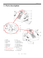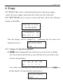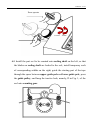
1
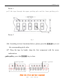
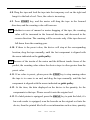
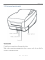
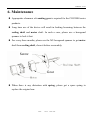
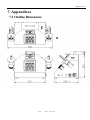
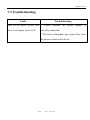
VERSION: .4.12 E SMD CHIP COUNTER COU2000ADV USER MANUAL 1/39 14:55 2011-2-22 VERSION: .4.12 E Preface Thank you very much for choosing TOPOINT SMD Chip Counter! You can use the COU2000 series products to achieve fast, convenient and error free in SMD chip counting, and better manage materials. Before using this device, please read this User Manual carefully first, and keep it properly. This product is subject to improvement and partial update without prior notice. Please contact our dealers or us if you have any questions. We recommend that you keep the packing materials for this device for future handling. Improper packing for this device may lead to its damage. Damage of the guaranty label resulting from unauthorized disassembling of the device parts will not be included guaranty services. 2/39 14:55 2011-2-22 VERSION: .4.12 E Contents 1. Matters for attention 4 2. Overview 6 2.1 Application 6 2.2 Features 6 2.3 Specifications 6 3. Parts description 7 3.1 ADV (basic function) 4. Usage 8 5. Option Function 17 6. Maintenance 34 7. Appendixes 7.1 Outline dimensions 35 7.2 FQA 36 7.3 Trouble shooting 38 7.4 Numerical part list 39 3/39 14:55 2011-2-22 VERSION: .4.12 E 1. Matters for attention After unpacking, please check the parts against the packing list. Incorrect power supply may damage the device, so please make sure that the power supply is in compliance with the specification. Please position the device at a stable and solid place. From the angle of ergonomics, we recommend that you use the device on a platform lower than 75 cm, because it is regarded as the optimal height which the user is able to sit at ease and see the display and the components in the pocket. z matters for label printer and barcode reader z Please make sure power supply specification is in compliance with the printer transformer request that you use ,otherwise the machine will be destroyed by fire consistently or can't work normally z Please don't try to change the printer enactment, and confirm consume material carbon is in compliance with the request of mark sign paper. Mark's signing paper and carbon can be bought from the material supplier allied department, if you have a special request, you can contact us or our retail business.. z The communication line of printer is one RS232 string, which is a special line material of our company, if you need to purchase them, please contact us or our retail business z This machine can only accept the importation that we recommend to output 4/39 14:55 2011-2-22 VERSION: .4.12 E device, the machine will be damaged or the device can't be driven if the outer device is changed by oneself. Statement of the range of environmental conditions: 1. Indoor use 2. Altitude up to 2000m 3. Temperature from 5℃ to 40℃ 4. Maximum relative humidity 80% 5. Main supply voltage fluctuations up to ±10% of the nominal voltage 6. Rated pollution degree Ⅱ 5/39 14:55 2011-2-22 VERSION: .4.12 E 2. Overview 2.1 Application COU2000 series products is a high efficient assisting equipment of SMD materials control, it is based on photoelectric theory. It makes use of the corresponding relationship between the tractive hole of the carrier tape and the pockets, so as to accurately determine the quantity of SMD parts, and achieve fast and convenient counting of the parts. It is undoubtedly a good help for materials management. 2.2 Features 2.2.1 High precision and free from counting errors. 2.2.2 All SMD general-purpose reeling packing parts are applicable. 2.2.3 Countable for in both forward and reverse directions, with double check feature; able to preset the quantity. 2.2.4 Simple operation and unique pocket falling-proof design will minimize the damage to the tape. 2.2.5 The patented inclined operation panel enables users to see the parts in both the display and the pockets. 2.3 Specifications SMD Chip Counter Compliant With Standards Electric Source 220-230 V~ ±10% 50Hz 60W/2A Counting range -59999----+59999 PCS Dimension(outer) 450*240*272mm (W*D*H) Weight 9.5 kg 6/39 14:55 2011-2-22 VERSION: .4.12 E 3. Parts description 1)Handle 12)LCD 2)Power switch 13)control panel 3)Reeling shaft 14)Printer interface 4)Motor 15)Barcode reader interface 5)Adjustable arm 16)Guide pulley 6)Locking knob 17)Upper guiding Pole 7)Power supply 18)Lower guiding Pole 8)output 19)Counter box 9)input changeable switch 20)Counter gear 10)spare power switch 21)Guide spring 11)Enclosure grounding point 22)Guide pulley 7/39 14:55 2011-2-22 VERSION: .4.12 E 4. Usage 4.1 Power on: select a workbench which closes to the power supply, connect the power supply, and position the cabinet onto the workbench. 4.2 Self check: press on power switch, and there will be the following display on the LCD: SMD CHIP COUNTER COU2000 SERIES YY MM DD HH :MM 20 04 05 26 14 : 59 Then the display will be changed to……indicating that the device has finished self check. DATA PITCH PRESET 00000 1 4.3. Usage of operation panel: z TIME: used to manage the time of the device; press the key to display the current time inside the device; press this key for ten seconds to enter the time setting display: YY MM 20 ** ** DD HH :MM ** **: ** Key in the corresponding year, month, date and time, press the TIME key, and the display will automatically return back to: DATA PITCH PRESET 8/39 00000 14:55 1 2011-2-22 VERSION: .4.12 E Time setting is finished. z POCKET CHECK: Applicable only to COU2000EX, it is used to check whether any components are absent in the pocket; press this key once to start the functions, and @ will be displayed on the upper left corner of the LCD; if there are any pocket without components, the device will automatically stop and give alarms. Press this key once again, and the pocket check function will become invalid. @DATA 00000 PITCH PRESET 1 ATTENTION: If there is no chip in the Pocket of the carrier tape, the Motor will stop, and the LCD will show that as followings: @***PCS CHIP LOST CHECK IT PLEASE! z PRINT: Applicable only to COU2000ADV and COU2000EX. It is used to print the quantity and the corresponding time; if a Bar-code reader is connected, barcode of the products will be printed on the label. Note: When the data is not a positive number, printing will be forbidden. z PITCH: Pitch value setting: according to the EIA-481 standard, the P: P0 ratio in the pockets fall within the following range: 1/2; 1; 2; 3; 4; 5; 6; 7; 8; 9; 10; 11; 12; 13; 14…; continue to press the PITCH key to set the correct pitch value. The pitch is equal to P/P0. That is, the pitch is equal to 9/39 14:55 2011-2-22 VERSION: .4.12 E the number of P0s between the two neighboring pockets on the carrier tape (the P0 for all the pockets is 4mm). 2 = h c t i p 1 = h c t i p o P 2 / 1o =P h c t i p Po o P 4 = h c t i p o P 3 = h c t i p PITCH=P/ P0 z PRESET: when it is expected that a certain number of parts are to be counted, Preset function is helpful. Press the Preset key, enter the value, the device will stop at the corresponding location, and the desired quantity can be got through simple fine tuning; press the Preset key again to clear the set value, and the advance stop function will turn invalid. DATA PITCH PRESET 00000 1 ***** Note: that the preset value above 59999 is invalid due to the Limitation of counting range. z CLEAR: use it to clear when beginning to count. z START: the motor on the right begins to rotate clockwise, the motor on 10/39 14:55 2011-2-22 VERSION: .4.12 E the left is driven, and the counting value increases. The tape will gradually be rolled into the temporary reel from the original reel. z STOP: the motor stops rotating. z REWIND: the motor on the left begins to rotate anticlockwise, the motor on the right is driven, and the counting value decreases. The tape gradually rolls from the temporary reel back to the original reel. Note that when the counting value decreases to zero, the device will stop automatically, at the time, the pocket shall be back to the starting point, so as to reconfirm the accuracy of counting; press the Rewind key, the tape will go on rewinding, until it returns completely back to the original reel from the temporary reel. 4.4. Rotate locking knob in the anticlockwise direction, adjust the adjustable arm: when using the 7 inch reel, please position the adjustable arm at the location 45 degrees to the cabinet; when using the 13 inch reel, please position adjustable arm at the location 45 degrees to the cabinet; rotate locking knob in the clockwise direction, and lock the adjustable arm with the fixing bracket fast, as illustrated in the following figure: 11/39 14:55 2011-2-22 VERSION: .4.12 E 7 inch reel / 45 Degree 13 inch reel / 90 Degree ·Rotate the Locking knob in the anticlockwise direction to make the arm in a flabby state.then adjust the adjustable arm to the angle that you want ,then Rotate the Locking knob in the clockwise direction to make the arm in a tightening state .please note that don’t pull or push the reel draft with hand, which may damage the gear box. You can slightly touch the arm as the following illustration. 12/39 14:55 2011-2-22 VERSION: .4.12 E Error operate LOOSE TIGHT 4.5. Install the part reel to be counted onto reeling shaft on the left, so that the blades on reeling shaft are locked to the reel; install temporary reels of corresponding widths on the right; guide the starting part of the tape through the space between upper guide pole and lower guide pole, press the guide pulley, and hang the tractive hole, namely, D in Fig. 1, of the reel onto counting gear. 13/39 14:55 2011-2-22 VERSION: .4.12 E Picture 1 pull the tape through the upper guiding pole and the lower guiding pole Picture 2 Fig. 1 4.6. According to item 4 mentioned above, please press the PITCH key to set the corresponding pitch value. 4.7. Drag the tape by hands, align the first component with the arrow indicated on guide pulley; press the CLEAR key to clear. start point end point About the first and last component 14/39 14:55 2011-2-22 VERSION: .4.12 E 4.8. Drag the tape and lead the tape into the temporary reel on the right and hang it to the hub of reel. Now, the value is increasing. 4.9. Press START key, and the motor will drag the tape in the forward direction, and the counting value will increase. Note: whether in cases of manual or motor dragging of the tape, the counting value will be increased in the forward direction, and decreased in the reverse direction. The counting will be accurate only if the tape does not fall down from the counting gear. 4.10. If there is the preset value, the device will stop at the corresponding location, drag the tape manually, until the last component is aligned with the arrow indicated on the guide pulley. . Note: because of the inertia of the motor and the different tensile forces of the pocket, the counting value where the device stops is often greater than the preset value. 4.11. If no value is preset, please press the STOP key to stop running when the tape is to come to an end, and drag the tape manually, until the last component is aligned with the arrow indicated on guide pulley. 4.12. At the time, the data displayed on the device is the quantity for the components in the tape. Please record it onto the original reel. 4.13. If a label printer is equipped, press the PRINT key to print the label; if a bar-code reader is equipped, scan the barcode on the original reel into the device, then the printed label will cover information such as time, quantity 15/39 14:55 2011-2-22 VERSION: .4.12 E and bar-code, as shown in the following figure: without bar-code of component V with bar-code of component 4.14. Press the REWIND key, and the tape will roll back from the temporary reel to the original reel. When the counting is decreased to zero, the device will stop automatically; drag the tape manually, and check whether the corresponding location zero at this time is consistent with location zero at start. This is called double check. 4.15. Press the REWIND key again, and all the tape will return back to the original reel. 16/39 14:55 2011-2-22 VERSION: .4.12 E 5. Option function Label Print and Barcode Copy Functions 1. Overview COU2000ADV/COU2000EX provides the function of label printing, which can list the results of SMD materials inventory check on labels of standard specifications in place of manual copying. The barcode copy feature can copy the barcodes on the original labels of material rolls onto new labels to avoid confusion. 2. Attention Items z This printer when in use will interfere with communications products such as radio and TV. So, when using the printer, please keep these products away from the printer. z Place the printer on a horizontal and solid desktop or plane, and keep away from places of humidity, water or high temperature. z Please be sure that the specifications of the power supply to be used are in compliance with the requirements for the printer’s transformer, which otherwise may result in device burning or abnormal running. z This printer will only serve as an output terminal of parts counter COU2000 series. The printer has been debugged and set with communications mode. For the specifications of character format, ribbon and label paper, please refer to the following table: 17/39 14:55 2011-2-22 VERSION: .4.12 E Programming language PPLB Printing model Thermal transfer printing Barcode format Code128 Resolution 200DPI Communication port RS232 serial port Carbon ribbon specification 80 mm Х100 m Label paper specification 65Х26 mmХ1000 pieces/roll Space: 2 mm Please do not try to change the printer’s setting, and be sure that the carbon ribbon of consumable material is in compliance with the requirements. The label paper and carbon ribbon can be purchased from the suppliers of consumable materials. In case of special-purpose requirements, you can contact us or our distributors. Note !! 18/39 14:55 2011-2-22 VERSION: .4.12 E 2. Operations 2.1 Label printing COU2000ADV and COU2000EX with label printing feature can all print labels. When counting is finished, the number of parts will be displayed on the screen. Press the PRINT key on the control panel, and the printer will print the labels of time and quantity of parts, as shown in the following figure: Labels not containing part specification barcode Barcode copy If a barcode reader is equipped, and the barcode on the original reel of the components are scanned into the device, then the time, quantity and parts’ specification barcodes will be printed, as shown in the following figure: Labels containing part specification barcode 19/39 14:55 2011-2-22 VERSION: .4.12 E 2. Installation 2.1 Unpacking and check Ensure the following items when unpacking z The printer’s face shall point upward. z Get out the fillings, and carefully get the printer out carefully. z Please place the printer on an even and solid surface, and be sure that there is no any damage due to transiting z Check whether all the following items are available: printer, barcode Reader User’s Manual, transformer, carbon ribbon, label paper and communication wire. 20/39 14:55 2011-2-22 VERSION: .4.12 E 2.2 Power cord connection and communication connection 2.2.1 Connecting printer’s power cord Keep the power switch at the “Off” location Connect one end of the transformer to the power socket of the printer, and he other end to the outer AC power supply. Note: when connecting the printer’s power socket, be sure to avoid close loop of parallel ports (contact is forbidden) 2.2.2. Be sure that the power supplies for both the printer and the counter are off. Use a special-purpose communication cable to connect the printer’s serial port (female) to the Mini Din 6 pin port (female) of the counter. Use screws to secure them to avoid loosening. 21/39 14:55 2011-2-22 VERSION: .4.12 E Attention Please: The cable is not a normal communication cable, It’s special just for COU2000 series of Topoint and OS214TT of Argox. 2.2.3. Connect the barcode reader’s communication cable with the barcode reader’s port (RS232 male) of the counter, and use screws to secure them to avoid loosening. Attention Please: 1. Select the AS8100 of Argox with a serial port, not a PS/2 port!!! 22/39 14:55 2011-2-22 VERSION: .4.12 E 2. Don’t plug in the power supply of the bar-code reader, The power supply (DC 5V) was concentrated in the chip counter!!! 3. Printer maintenance 3.1 Printer structure 23/39 14:55 2011-2-22 VERSION: .4.12 E 24/39 14:55 2011-2-22 VERSION: .4.12 E 3.2 Paper placement 3.2.1 Uplift the upper cover of the printer, and keep it at the Open location. 3.2.2 Lift the paper roll support axis, insert the paper roll support axis into the paper tube in the middle of the label paper, place it into the paper tray of the printer, and the baffle shall be placed on the right, flush to the left. 25/39 14:55 2011-2-22 VERSION: .4.12 E 3.2.3 Loosen the locking bar of the printing head, and turn the printing head’s module to the vertical location. 3.2.4 Pull out the label paper, run it through the paper width adjusting slot at the bottom of the printing head module. 3.2.5 Move the sliding block on the right to the left, get the paper tight, at the same time, pull out the label paper to the appropriate location, and be sure that it is outside the printing head module. 3.2.6 Recover the printing head module, and be sure that the module has been 26/39 14:55 2011-2-22 VERSION: .4.12 E completely locked into the printing head’s locking bar. 3.2.7 Recover the printer’s upper cover. 27/39 14:55 2011-2-22 VERSION: .4.12 E 3.3. Paper testing Press the FEED key, turn on the power supply, until the printer’s motor is started. The printer will automatically feed out label of a certain length, and thus is finished the paper testing. 3.4 Carbon Ribbon installation 3.4.1 Lift the printer’s upper cover, and keep it at the OPEN location. 3.4.2 Loosen the printing head’s locking bar, open the printing head’s module, and adjust it to the vertical location. 28/39 14:55 2011-2-22 VERSION: .4.12 E 3.4.3 Open the carbon ribbon, and lock the carbon ribbon’s supply end into the carbon ribbon’s supply end slot (first, lock the paper tube on the left of the carbon ribbon into the left slot, apply force slightly on the left, and then lock the paper tube on the right of the carbon ribbon into the right slot.) 3.4.4 Lock the carbon ribbon recovery end’s paper tube into the carbon ribbon recovery end’s slot (the step is the same as above), and then slightly roll the gear for a cycle. 29/39 14:55 2011-2-22 VERSION: .4.12 E 3.5 Printer panel operation guide Power Switch Control power connection or disconnection status Note: when connecting communication lines or power cords, be sure that the switch is on the OFF location. 30/39 14:55 2011-2-22 VERSION: .4.12 E FEED Key Feed paper to the next location Press slightly once—Feed paper to the next location In the continuous print status, slightly press the FEED key—Enter the pause status Slight press the FEED key in the pause status—Enter the normal print status Ready Indicator Display the power and error statuses OFF—the printer is off Green—the printer is started Flash—there is an error, and check against the following table: The POWER and READY indicators “The POWER and READY flash contemporaneity indicators flash alternately Possible problem Solution Possible problem Label spacing Check the label path The carbon ribbon Reinstall carbon cannot be found Check the label is used up Solution ribbon detector Paper is used up Reload paper roll The carbon ribbon Clean up the carbon is blocked ribbon The paper roll is Load the paper roll The carbon ribbon Replace the carbon not loaded detector goes wrong ribbon detector Paper is blocked Remove the fault 31/39 14:55 2011-2-22 VERSION: .4.12 E 4. Basic maintenance steps: 4.1 Cleaning the printing head and sensor 4.1.1 Cleaning the printing head is the most important and fundamental maintenance. First, use cotton (or tampons and other cleaning means with less flocking and smoothness) dipped with alcohol to wipe the heating line on the printing head in the “unidirectional” mode. Be sure that the carbon is cleaned up, and then wipe another two times for confirmation (one time of maintenance can be done when one roll of paper is used up). 4.1.2 Cleaning sensor is to ensure that the device is able to keep the correct spacing between papers and ensure the security of detecting carbon ribbons. If no cleaning is done for a long time, dust in the air will deposit on the sensor. After a long time, the light source of the sensor will be in malfunction. So, please use an air pressure bottle without any elements, and the amount of spray and wiping will be determined by the operating environment of the device (one time of maintenance for every one month). 4.2 Cleaning, maintenance and lubrication of paper carbon ribbon paths and joints 4.2.1Clean along the path installed with paper and carbon ribbon, so that paper and carbon ribbon can more smoothly operate. Examine the various rotating nodes or rollers, and clean the deposit on the surface to lubricate 32/39 14:55 2011-2-22 VERSION: .4.12 E the various parts with lubricating oil (one time of maintenance for about every three months). Maintain the carbon ribbon’s recovery roller and installation axis. However, after maintenance, the force of each axis shall be readjusted to prevent phenomena such as corrupting from happening. Customers are not encouraged to clean on their own (one time of maintenance for every three moths). 33/39 14:55 2011-2-22 VERSION: .4.12 E 6. Maintenance z Appropriate cleanness of counting gear is required for the COU2000 series products. z Long time use of the device will result in locking loosening between the reeling shaft and motor shaft. In such a case, please use a hexagonal spanner to lock it fast. z For every three months, please use the M3 hexagonal spanner to get motor shaft from reeling shaft, clean it before reassembly. Screw Gear z When there is any distortion with spring, please get a spare spring to replace the original one. 34/39 14:55 2011-2-22 VERSION: .4.12 E 7. Appendixes 7.1 Outline Dimension: 35/39 14:55 2011-2-22 VERSION: .4.12 E 7.2. FQA Q1: When printing labels, the printed part deviates in one direction, how to improve it? A: Reload the label paper, be sure that it is against the baffle, flush on the left, and adjust the sliding slot of the paper width at the bottom of the printing head’s module. Q2: There is one or more blank papers. A: Please calibrate, and once again detect the size of label. If the problem remains, please follow these steps to solve the problem. 1. The size of the actual label is not in compliance with the required label size. 2. The label transparence is abnormal, please use the barcode device’s special-purpose label paper. Q3: No display of barcode. A: Probably, the barcode format is not accepted. Please select the correct barcode; or the barcode is not scanned. Generally speaking, the LED of the barcode reader will be lit when scanning barcodes, and sound BEBE. 36/39 14:55 2011-2-22 VERSION: .4.12 E Memory of barcode reader always keeps only one barcode, and new barcode will automatically cover the old one and be cleared after each printing output. This is to ensure accuracy of barcode copying. Q4: No display of some barcodes. A: At present, the maximum acceptable length of barcode is 24 digits, and no additional length can be displayed. Q5: Press the PRINT key, but the printer refuses to work. A: The printer is not connected or not powered on; when the data is not a positive number, printing is prohibited. 37/39 14:55 2011-2-22 VERSION: .4.12 E 7.3 Troubleshooting Fault Troubleshooting Turn on the power switch, and 1. Check whether the power supply is there is no display on the LCD correctly connected; 2. The fuse is damaged, get a spare fuse from the power socket in the device. 38/39 14:55 2011-2-22 VERSION: .4.12 E 7.4 Numerical part list Part Cou2k-b Description Cou2000 cabinet without communication board, without pocket check kit Spring Spring of guide pulley 39/39 14:55 2011-2-22