1
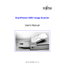
ScanPartner 600C
Image Scanner
User's Manual
Version 1.0
Fujitsu Computer Products of America, Inc.
Notice
FCC Class B Computing Devices
(Federal Communications Commission Radio Frequency
Interference statement)
This equipment has been tested and found to comply with the
limits for class B digital device, pursuant to Part 15 of the FCC
rules. These limits are designed to provide reasonable
protection against harmful interference in a residential
installation. This equipment generates, uses and can radiate
radio frequency energy and, if not installed and used in
accordance with the instructions, may cause harmful
interference to radio communication. However, there is no
guarantee that interference will not occur in a particular
installation. If this equipment does cause harmful interference to
radio or television reception, which is determined by turning the
equipment off and on, the user is encouraged to attempt to
correct the interference by one or more of the following
measures:
•
•
•
•
Reorient or relocate the receiving antenna.
Increase the separation between the equipment and
receiver.
Connect the equipment to an outlet on a separate or
dedicated circuit.
Consult the dealer or an experienced radio/TV technician
for help.
CAUTION: Any changes or modifications not expressly
approved by the manufacture of this device could void the
user's authority to operate the equipment.
ii
Table of Contents
1. SCANNER INSTALLATION ......................................................... 1-1
1.1 PRECAUTIONS ................................................................................ 1-1
1.2 ASSEMBLING THE SCANNER ............................................................ 1-1
1.3 CONNECTING THE SCANNER ........................................................... 1-6
2. SCANNER OPERATION...............................................................2-12
2.1 USING THE FLATBED .....................................................................2-12
2.2 USING THE ADF............................................................................2-13
3. MAINTENANCE............................................................................3-15
3.1 CLEANING THE ADF .....................................................................3-15
3.2 CLEANING THE GLASS ...................................................................3-17
4. TROUBLESHOOTING .................................................................. 4-1
4.1 QUESTIONS AND ANSWERS ............................................................. 4-1
4.2 TECHNICAL SERVICE ...................................................................... 4-3
5. SPECIFICATIONS.......................................................................... 5-1
Table of Figures
FIGURE 1-1 SCANNER PACKING ............................................................... 1-2
FIGURE 2-1 REMOVING THE SHIPPING RETAINER ....................................... 1-2
FIGURE 2-2 STORING THE SHIPPING RETAINER .......................................... 1-2
FIGURE 2-3 INSTALLING THE ADF PAPER CHUTE ...................................... 1-4
FIGURE 2-4 INSTALLING THE STACKER ..................................................... 1-5
FIGURE 2-5 TYPICAL SCSI CHAIN ........................................................... 1-7
FIGURE 2-6 SELECTING THE SCSI ID....................................................... 1-8
FIGURE 2-7 CONNECTING THE SCANNER .................................................. 1-9
FIGURE 2-8 SCSI TERMINATION SWITCH................................................1-10
FIGURE 3-1 USING THE FLATBED ............................................................2-12
FIGURE 3-2 USING THE ADF ..................................................................2-14
FIGURE 4-1 CLEANING THE ADF ............................................................3-16
FIGURE 4-2 CLEANING THE GLASS ..........................................................3-17
1-3
Introduction
Congratulations on your purchase of the Fujitsu ScanPartner
600C scanner.
Before you install and operate the new scanner, please take a
few minutes to read through this manual. It provides you
with the proper instructions on how to unpack, install,
operate and maintain the scanner.
Figure 1-1 shows how the scanner is packed. You can check all
items against your checklist.
Figure 1-1 Scanner packing
1-2
1. Scanner Installation
1.1 Precautions
•
•
•
•
•
Keep the scanner out of direct sunlight. Direct exposure to
the sun or excessive heat may cause damage to the unit
Do not install the scanner in a humid or dusty place
Be sure to use the proper AC power source
Place the scanner securely on an even, flat surface. Tilted
or uneven surfaces may cause mechanical or paper-feeding
problems
Retain the scanner box and packing materials for shipping
purposes
1.2 Assembling the Scanner
Please unpack the scanner carefully, and check the contents
against the checklist provided. If any items are missing or
damaged, please contact your authorized local dealer
immediately.
Removing the Shipping Retainer
Your ScanPartner 600C comes with a factory installed shipping
retainer designed to protect the scanner during shipment.
Before your scanner can be used, the shipping retainer must be
removed. Follow these instructions to remove the shipping
retainer:
1. Lay the scanner on its side as shown in Figure 1-1
2. Unscrew the retainer screw and remove the shipping retainer
3. Place the shipping retainer in the “use position” slot and
secure it with the retainer screw (see Figure 1-2)
4. Place scanner back in its normal position
1-1
Figure 1-1 Removing the shipping retainer
Figure 1-2 Storing the shipping retainer
1-2
Installing the Shipping Retainer
Before moving or transporting the scanner, the shipping retainer
must be installed to prevent damage in shipment. Follow these
instruction to install the retainer:
1. Turn off the scanner.
2. Lift the document cover so that the carrier unit can be seen
3. Turn on the scanner. The carrier unit will move forward and
stop for a few seconds. Turn off the scanner during this
pause.
4. Lay the scanner on its side as shown in Figure 1-2
5. Remove the retainer from the “use position” slot and install
it in the “ship position” slot
Your scanner can now be safely transported.
1-3
Installing the ADF paper chute
1. Raise the right side of the paper chute to about 45 degrees
(see Figure 1-3)
2. Pull down the wire leg from under the paper chute.
3. Insert the wire leg into the grips on the document cover.
4. To extend the length of the paper chute, gently slide out the
paper chute extension
Figure 1-3 Installing the ADF paper chute
1-4
Stacker Installation
1. Hold the stacker at an approximate 30 degree angle as
shown in Figure 1-4
2. Insert the stackers three clasp-joints into holes located on
the ADF.
3. Release the stacker gently. Make sure the stacker is firmly
attached to the ADF.
4. To extend the length of the stacker, gently pull out the
stacker extension wire
Clasp
joint
Figure 1-4 Installing the stacker
1-5
1.3 Connecting the Scanner
CAUTION: Before connecting the scanner, make sure the
power to the computer is OFF
This section describes how to connect your new ScanPartner
600C. Also provided is a brief overview on daisy chaining and
terminating SCSI devices. If you are an advanced user and are
already familiar with the use of SCSI devices, you can skip the
overview.
SCSI Overview
One of the biggest advantages to using SCSI as an interface is
the ability to connect several devices to one SCSI controller or
“SCSI port.”
Each SCSI controller can have up to 7 devices connected to it.
This is referred to as daisy chaining or chaining. A SCSI chain
can consist of internal devices, such as hard disks and CD ROM
drives, and external devices, such as the ScanPartner 600C. Not
all SCSI controllers are capable of handling a combination of
internal and external devices but most are.
The key factor when chaining SCSI devices is the device ID.
Each device must have a unique ID. The SCSI controller itself
must have an ID and, in most cases, is 7. This leaves 0-6
available for use as device ID’s. Although it is not reserved,
device ID 0 is generally used for SCSI hard disks. It is not
recommended that you use ID 0 for an external device.
Most SCSI devices provide a method for the user to set the
device ID. This can be done via software or with a switch. In
some case the operating system may decide which ID to apply
to a device.
One other key factor to a SCSI daisy chain is that each end of
the chain must be terminated. Termination can be done many
ways but the most common method is to apply a SCSI
1-6
terminator connector. The purpose of the terminator is to tell
the controller that there are no more devices on the chain and
that it should not look beyond this device for another device.
Most (but not all) SCSI devices are equipped with 2 SCSI
connectors: one for the connection cable and one to chain or
terminate. Regardless of the methods used, each end of the
chain must be terminated.
In most cases, the controller itself provides termination at one
end of the chain. Termination at the other end must be provided
by the last device on the chain.
Figure 1-5 shows a typical SCSI chain.
Terminator
Host computer
with SCSI
Contoller
SCSI Device
SCSI Device
SCSI Device
Terminator
Figure 1-5 Typical SCSI Chain
Installing the SCSI Controller
For information on installing the SCSI controller, follow the
instructions provided with the controller.
Setting the SCSI Device ID
When you have several devices on a SCSI chain you may need
to adjust the SCSI ID selector setting located on the back of the
scanner. This setting assigns a specific "device ID" to the
scanner. If the assignment conflicts with an existing SCSI
device, please select a new ID. (See Figure 1-6)
Note: The factory setting for ScanPartner 600C is ID 6. Usually,
ID 0 is assigned to an internal hard disk drive, and ID 7 is
assigned to the SCSI host adapter. ID 8 and 9 are not
used.
1-7
SCSI ID Selector
Figure 1-6 Selecting the SCSI ID
1-8
Connecting the Scanner
See Figure 1-7 for a connection diagram.
1. Connect one end of the SCSI cable to the SCSI controller
installed in the computer
2. Connect the other end of the SCSI cable to SCSI port
located on the back of the scanner
3. Connect the power cable to the power input port located on
the back of the scanner
Plug the power cord into the power source.
Figure 1-7 Connecting the scanner
1-9
Terminating the Scanner
As with any SCSI device, the ScanPartner 600C must be
properly terminated before use. The ScanPartner 600C uses a
terminator switch located on the back of the scanner, therefore
a SCSI terminator is not required.
If the ScanPartner 600C is the last device on the SCSI chain
then the terminator switch must be set to the ON position, see
Figure 1-8. If the ScanPartner 600C is not the last device on the
SCSI chain, the terminator switch must be set to the OFF
position.
Figure 1-8 SCSI Termination Switch
1-10
Turning on the Power
The power is controlled by a toggle switch on the side of the
scanner. To turn on the scanner, press the switch toward "1."
The POWER LED will light. If it does not light , please check
the power.
Scanner Diagnostics
The scanner has a built-in self-diagnostic function to detect
system errors. The self test is initiated each time the scanner is
turned on. During the test, the ERROR LED will light on. At
the end of the test, if no error occurs, the ERROR LED should
extinguish.
1-11
2. Scanner Operation
2.1 Using the Flatbed
To use the flatbed, open the document cover and place the documen
face down on the glass document board. Make sure the corner of the
document is placed against the reference mark
Figure 2-1 Using the flatbed
2-12
2.2 Using the ADF
The ScanPartner 600C comes equipped with ADF capable of
holding up to 50 sheets of standard copier paper. The actual
number of documents may vary depending on the types of paper
being scanned.
The ScanPartner 600C ADF feeds one document at a time.
Before using the ADF, always prepare you documents by:
• removing any staples, paper clips, or any other item
used to attach more than one sheet of paper
• fan the paper stack to remove friction between pages
• ensure that stack has a flush leading edge
To use the ADF:
• adjust the document guides to the width of the
documents to be scanned
• place the documents head first and face down into the
ADF
The following list shows items and paper types that should not
be fed through the ADF
•
•
•
•
•
•
•
•
•
Paper with clip or staple attached;
Paper with ink not totally dry;
Paper with inconsistent thickness, such as
envelopes;
Paper with wrinkles, curls, folds or tears;
Tracing paper;
Coated paper;
Carbonless paper;
Paper narrower than 3.5" or wider than 8.5";
Items other than papers, such as cloth, metal or
2-13
OHP film;
•
Notched paper
•
•
Paper with an odd (non-rectangular) shape;
Very thin paper.
Figure 2-2 Using the ADF
2-14
3. Maintenance
Your scanner is designed to be maintenance free. However, to
ensure peak performance and optimum image quality, the
scanner must be cleaned occasionally.
The feed mechanism of the scanner may become contaminated
with ink, toner particles or paper coatings which may result in
feed problems, such as:
• Documents do not feed smoothly or easily or
• Several documents feed at one time.
If you experience these problems then it is recommended that
you clean the ADF as described below.
3.1 Cleaning the ADF
Use the following procedure when cleaning your scanner (see
Figure 3-1):
1. Dip a cotton swab in isopropyl alcohol. (95%)
2. Open the ADF unit and wipe the upper feeding roller
by moving the swab from side to side. Rotate the
roller forward with your finger and repeat the above
cleaning procedures until the entire roller is cleaned.
Be careful not to snag or damage the pick springs.
3. Wipe the pad in the direction from top to bottom. Be
careful not to hook the pick springs.
4. Allow to dry
5. Close the ADF unit.
3-15
Figure 3-1 Cleaning the ADF
3-16
3.2 Cleaning the Glass
Use the following procedure to clean the glass document
board:
1. Soak a cotton swab with some isopropyl alcohol.
(95%)
2. Open the document cover as shown in Figure 3-2
3. Wipe the glass of flatbed area by moving the swab
from side to side.
4. Allow to dry.
5. Close the document cover.
Figure 3-2 Cleaning the glass
3-17
4. Troubleshooting
The scanner will automatically perform a simple self-test
each time it is turned on. This will help spot major system
errors in the scanner itself.
When the self test is initiated, the ERROR LED will become
lit and will remain lit for the duration of the test. When the
test is complete, the ERROR LED light will go out.
If you have problems with the operation of your scanner,
please check the following troubleshooting hints.
4.1 Questions and Answers
Question: The LED indicates that the scanner is ready, but
the scanner does not respond to the scan
command from the host computer.
Answer: Please check the signal cable is firmly seated, and
invoke the scan command again. If there is still
no response, please reset the scanner by turning
it off and then on again, and reboot your host
computer as well.
Question: Paper becomes jammed during scanning.
Answer: Open the ADF unit and carefully pull out the
jammed document
Question: More than one sheet of paper was fed into the
scanner.
Answer: 1) Open ADF unit.
2) Remove the multi-fed sheets of paper.
3) Close the ADF unit.
4) Flatten the corners and edges; loosen the
paper before reloading it in the paper guide.
4-1
5) Check the feeding roller condition and do the
cleaning if necessary.
Question: Paper becomes skewed in the scanner.
Answer: Check the condition of the feed roller and
cleaning if necessary.
Question: When I power on the scanner, it makes noises
and will not stand ready.
Answer: Possibilities for this condition are:
1) The shipping retainer was not removed from
the bottom of the scanner or
2) The scanner is not sitting on a flat surface.
This may cause the scanner to function
improperly.
Question: When I power on the scanner, the lamp does
not come on.
Answer: Contact your authorized local dealer or service
provider.
Question: Sometimes while scanning the scanner hangs or
the system crashes.
Answer: Make sure that:
1) The SCSI cable is firmly seated and
2) the SCSI bus is terminated and configured
correctly.
4-2
4.2 Technical Service
Technical support for Fujitsu scanners is provided at Fujitsu
Technical Assistance Center (TAC) at 1-408-894-3950
from 7 a.m. to 5 p.m. PST. Before contact with TAC,
please prepare the following information.
• Scanner serial & revision number (located on the
bottom of the scanner);
• Hardware configuration (e.g., your host CPU type,
RAM size, free disk space, display card, interface
card...);
• The name and version of your scanning software
application;
• The version of your scanner driver.
4-3
5. Specifications
The following specifications for the ScanPartner 600C are
subject to change without notice.
Scanner Type
Single-pass color
Flatbed with ADF built-in
24-bit color
8-bit Grayscale (256 levels)
Line Art/Halftone
Error Diffusion (single bit)
600 * 1200 dpi
Cold cathode fluorescent lamp
50 pages
15 PPM (200dpi , B/W mode)
ADF mode 8.5“ x 14”
Flatbed mode 8.5“ x 11.69”
SCSI-2
TWAIN, ISIS
100 to 240 Vac, 47 to 63 Hz
35 watts
20% to 80% RH
10 to 40
-10 to 50
570 x 350 x 165 mm (WxDxH)
Approximate 26.5 lbs (12 kg)
Scanning Mode
Optical Resolution
Light Source
ADF Capacity
ADF Scanning Speed
Scanning Document Size
Interface
Drivers
Power Requirement
Power Consumption
Humidity
Operation Temperature
Storage Temperature
Dimension
Weight
5-1