1
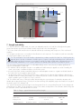
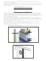
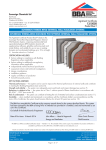
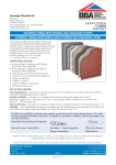
Figure 2 Typical section at base
mechanical fixing
RetroBase
reinforcement mesh
primer
topcoat
insulation
ground floor edge insulation system
(outside scope of Certificate)
7 Strength and stability
7.1 When installed on suitable walls, the system can adequately transfer to the wall the self-weight and negative
(suction) and positive (pressure) wind loads normally experienced in the United Kingdom.
7.2 Positive wind load is transferred to the substrate wall directly via bearing and compression of the render and
insulation.
7.3 Negative wind pressure is resisted by the bond between each component. The insulation boards are retained by
the external wall insulation system anchors.
7.4 The wind loads on the wall should be calculated in accordance with BS EN 1991-1-4 : 2005 and its UK
National Annex. Special consideration should be given to locations with high wind-load pressure coefficients as
additional fixings may be necessary. In accordance with BS EN 1990 : 2002 and its UK National Annex, it is
recommended that a load factor of 1.5 is used to determine the ultimate wind load to be resisted by the system.
7.5 Assessment of structural performance for individual buildings must be carried out by a suitably qualified and
experienced individual to confirm that:
• the substrate wall has adequate strength to resist additional loads that may be applied as a result of installing the
system, ignoring any contribution that may occur from the system
• the proposed system, and associated fixing layout, provides adequate resistance to negative wind loads based on
the results of the site investigation and test results
• an appropriate number of site-specific pull-out tests are conducted on the substrate of the building to determine the
minimum resistance to failure of the fixings. The characteristic pull-out resistance should be determined in accordance
with the guidance given in ETAG 014 : 2011, Annex D.
7.6 The number and centres of fixings should be determined by the system designer. Provided the substrate wall is
suitable and an appropriate fixing is selected, the mechanical fixings will adequately support and transfer the weight of
the render system to the substrate wall.
7.7 Typical characteristic pull-out strengths for the fixings taken from the corresponding European Technical Approvals
(ETAs) are given in Table 3 of this Certificate; however, these values are dependent on the substrate and the fixing must
be selected to suit the loads and substrate concerned.
Table 3 Fixings — typical characteristic pull-out strengths
Fixing type
Ejotherm STR-U
Ejotherm NT-U
Rawlplug KI–10
Rawlplug TFIX-8M/8S
ETA No.
Substrate
Typical pull-out strength
(N)
04/0023
Concrete C12/15/clay bricks
1500
05/009
Concrete C12/15/clay bricks
1200/1500
07/0291
clay bricks
500
07/0336/11/0144
Concrete C12/15/clay bricks
1200
Page 7 of 17