1
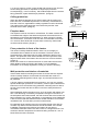
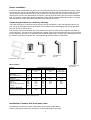
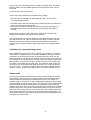
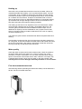
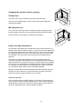
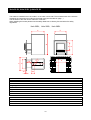
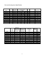
Wood burning sauna heaters
Installation and user’s manual
314 PKLE 30 B
1
Thank you for choosing quality products from Helo
We think that our products will live up to your expectations and give you many hours of enjoyment in your
sauna. We want you, your family and friends to have many comfortable sauna baths and at the same time
find new ways to enjoy the sauna bathing.
Helo is the world-leading producers of products for saunas and steam saunas. We develop, produce and
market products for saunas and steam saunas in the world. Saunatec has the largest factories of sauna
products in the world (Finland, Germany and the USA) and a well-developed network of retailers, both
nationally and internationally. Our product range consists of sauna and steam rooms, electric and wood
heaters, control panels and sauna accessories.
Helo Group Ltd
User Guide. Wood-burning sauna heaters
Copyright@2004. Helo Group Ltd. All rights reserved.
2
Index
Preparing the heater for use
4
Minimum safety distances
4
Wall protection and choices of material
6
Installation
7
Installation of heaters with front water tanks
8
Ventilation in a wood-burning Sauna
8
Sauna rocks
8
Heating up
9
Water quality
9
Mounted water tank
9
Changing the direction of door opening
10
Heater care and maintenance
10
Troubleshooting
11
Helo 20SL, Helo 28SL, Helo 38SL, Installation
12
3
Preparing the heater for use
Read the instructions carefully before the first use!
The heater is painted with heat-resistant paint and due to its chemical properties it may evaporate burning
odours from its surface when heated for the first times. Therefore we recommend the first heating up to be
done outdoors or in a well-ventilated sauna room. The first pre-heating must be done without stones. If the
sauna stove is heated up outdoors it should be done with a 2 metre connecting pipe installed in order to get
a good draught. In preheating the continuous heating with 3-5 loads of wood should be enough to remove
the anti-corrosion substances from the heater.
One of the paint properties is that it reaches its final state only during the first heating times. Thus rubbing
and wiping of the painted surfaces should be avoided before the first use. Handle the heater with care. The
heater is likely to release paint odour for some time as any other painted materials.
Adjustable feet
The heater can be equipped with optional adjustable feet (shown here).
Adjustable feet facilitate the installation of the heater on an inclined floor.
Installation point
Make sure there is enough space for installation and observe the safety distances. Heating up requires
1 m x 1 m around the heater. Place the heater far enough from combustible materials and protect the
floor if the floor is tiled. See that there is space in the niche for air circulation (minimum of 100 mm).
Remember that the sauna rocks decay over time causing fine-grained rock material to fall to the floor with
the steam water. The heat generated by the furnace and temperature changes may also cause small metal
flakes to fall to the floor which is a normal property of metal.
Due to the above-mentioned facts it is a good idea to avoid using light-coloured materials near the heater.
Always check the heat resistance of the tiles with the supplier.
Keep the floor under the heater clean.
Minimum safety distances
Minimum safety distances between the heater and combustible materials:
from the sides and back of the heater: 500 mm
from the front of the heater: 1000 mm
from the top of the heater to the ceiling: min.1200 mm
from the heater to the floor (see Floor protection): min. 500 mm.
Statutory minimum safety distances to combustible materials can be reduced by half with single-layer and
by 75% with double-layer light protection.
4
Image 1.
Side walls
1. Minimum safety distance from the vertical surfaces of the heater to
unprotected wood structures: 500 mm. (Image 1).
500
Wood-burning sauna heaters are classified as burning surface fireplaces.
The surface temperature of the heater will not rise above 350 °, and the
following minimum safety distances should be observed. Combustible
structural parts, such as wood walls, benches, etc.
500
Image 2.
A minimum of 30 mm air gap must be left between the wood surface
being protected and the protective sheet using, for example, duct
bushings as spacers. (Image 2).
250
2. The minimum safety distance mentioned in item 1 can, however, be
reduced to no less than 250 mm when using ”single-layer” protection.
This type of light protection can be made of minimum of 7 mm thick
non-combustible, fibre-reinforced concrete sheets or minimum of
1 mm thick metal sheet tightly mounted to the wall.
300
250
Mounting bolts
30mm air gap
1mm metal sheet or
7mm non-combustible,
fibrereinforced concrete
sheet
3. The minimum safety distance shown in picture 1 can be further
reduced to minimum of 125 mm when using double-layer protection.
Image 3.
125
Double-layer protection can be made two sheets mentioned in item 2
leaving a minimum of 30 mm air gap between the wall and sheet.
(Image 3).
300
125
Mounting bolts
30mm air gap
1mm metal sheet or
7mm non-combustible,
fibrereinforced concrete
sheet
Image 4.
50
4. If the wall is made of masonry, a 50 mm air gap between the vertical
surfaces of the heater and the walls will be sufficient. (Image 4).
A
Measurements A is for wood surfaces depending
on the type of protection used.
- Without protection: 500 mm
- With single-layer protection: 250 mm
- With double-layer protection: 125 mm
5
Image 5.
5. A 55 mm masonry, which is open-ended and at least 30 mm from the
surface being protected, is equivalent to single-layer protection.
Correspondingly, 110 mm masonry, which stands apart from the surface
being protected, equals double-layer protection. (Image 5).
400
400
Ceiling protection:
When the distance between the top of the heater and the ceiling is at
least 1200 mm, no additional protection is necessary. If the distance is
less than 1200 mm, applicable fire safety regulations must be observed.
The edges of the ceiling protection must extend beyond the outer
surfaces of the heater. (Image 6).
110/55mm
Fireplace base
F mm
The fireplace must be mounted on a fixed base. The base must be able
to withstand the weight of the heater and prevent the excessive rise in
temperature of structural parts attached to it. When mounting a heater
onto a wood floor, a minimum of 50 mm thick concrete slab or minimum
of 7 mm thick fibre-reinforced concrete sheet covered by sheet metal
must be used as a base. (Image 7).
Ceiling (no protection) 1200
F
Single-layer light
protection
Floor protection in front of the heater:
Wall protection and choices of materials
If the wooden walls surrounding the heater are closer than the required
minimum safety distance recommends and the walls are made of a
combustible material (panels, boards, logs, etc) the wall surfaces must
be protected.
A 55 mm masonry equals single-layer protection, and 110 mm masonry
equals double-layer protection. The masonry must be open-ended and at
least 30 mm from the surface being protected, extending 600 mm above
the top of the heater and have a 500 mm minimum safety distance on
each side.
Wood materials used in the sauna room, such as panels, will darken over
time. This darkening is caused by temperature changes in the sauna. If
the wall panels have been treated, the wall surfaces above the heater will
begin to darken very quickly, depending on the treatment used. Darkening
is due to the fact that the treatment has a weaker resistance to heat than
untreated wood. This has been proved in material tests.
Fine-grained stone particles rising from crumbling sauna rocks with air
currents may darken the wall surfaces around the heater. If the heater
installation instructions are followed, the heater will not heat up
combustible materials used in the sauna room to a dangerous level. The
maximum allowed temperature for wall and ceiling surfaces is +140 °C.
Note! Glass and stone surfaces!
6
100
400
The minimum safety distances listed in items 1-5 do not apply to
combustible floor materials in front of the heater. The floor must be
protected with a metal sheet which is tightly fastened to the floor and
heater. This protection must extend at least 100 mm beyond the outer
edges on both sides of the heater door and 400 mm out from the door.
(Image 7).
Note! There must be no electrical devices or wires within the minimum
safety distance area surrounding the heater. For more detailed
information on fire safety regulations consult your local fire authority.
100
900
Heater installation
In all our heater models there is a port for the connecting flue duct on top of and behind the heater. Close
the unused port with the cap provided. With the heater there is also a 200 mm connecting flue duct, which
can be used for rear-mounted flue ducts. Do not push the connecting flue duct too far into the chimney –
this will block air flow. The gap between the masonry chimney and connecting flue duct must be insulated
with, for example, mineral wool. During installation ensure that the heater is fastened securely on its base,
and that all the minimum safety distances listed in this manual are correct.
Connecting the heater to a masonry chimney
There are two ways to connect the connecting flue duct to the chimney. If the connecting flue duct is run
from the top of the heater, the port in the back of the heater must be closed tightly with the cap provided
(remove the cap on the top port).
The masonry connector is bricked into a hole made in the chimney at the correct height for connection to
the flue duct port. The flue duct is connected to the heater, which is removed when the flue duct is inserted
into the masonry connector. The optional flue duct feed-through collar is used to give a finishing touch over
the masonry work around the flue duct. The feed-through collar is made of noble metal.
Masonry connetor
Connectin flue
o
duct 90
Connectin flue
o
duct 60
o
Feed-through collar 115mm
HELO heaters
Model R
from
behind
Heat-retaining,
ever ready
HELO UKKOTONTTU
Soapstone heater
HIIDENKIVI
Continuous heating
HELO 12
HELO 20 SL
HELO 20 BLACKLINE and
HELO 40
Heaters w/ water tank
HELO 18 ES BLACKLINE
Flue port height to port centre
on top w/ 60º
90º
upper tank + 60º
connecting flue
connecting flue
duct
duct
Connectin flue duct
330-1000 mm
duct-mounted
tank + 90º
connecting duct
780
-
-
-
-
590
1010
840
1630
1470
550
600
600
930
970
1020
1020
1380
800
850
850
1200
1590
1640
1640
-
1430
1480
1480
-
650
1070
900
-
-
Note! These are measurements without adjustable feet
Installation of heaters with front water tanks
Permanently mounted to the front of the heater, the 24-litre hot water tank is
made of high-quality noble steel. The faucet can be installed either on the left
7
or right side. The unused faucet port is closed with a plug. Note! The faucet
and plug seals must be installed against the outer wall of the tank, not the
inner wall.
Tips to ensure proper tank function:
• Never heat up the heater when the water tank is empty.
• The water tank is intended for heating bathing water – do not put any
corrosive detergents into it.
• The water used in the tank should be high-quality tap water (pay attention to
saline, iron, lime and humus content)
• The water tank must be emptied and dried if it will remain unused for an
extended period of time. This will prevent the build-up of slime and/or
freezing.
Note! Exercise extreme caution with boiling water in the hot water tank.
Boiling water and steam can seriously burn the skin!
Turning the handle on top of the heater 90° will release the water tank side
from the stone tray wall. This will slow down the boiling of water in the tank.
Remember to clean the water tank surfaces with stainless steel cleaner.
Iron-rich water may leave rust-like spots. Clean these with a stainless steel
cleaner.
Ventilation in a wood-burning sauna
Good ventilation plays a crucial role in creating truly enjoyable, comfortable
sauna steam. The traditional rule for natural ventilation is to bring in fresh air
just above floor level near the heater, and discharge the air as far from the
heater as possible, near the ceiling. Because the heater itself is very effective
at circulating air, the exhaust port is primarily used to discharge moisture after
taking a sauna. Incoming air brought in near floor level runs up between the
hot interior of the heater and its outer shell. The heated air rises up through
the grate on top of the heater and heats the sauna room. Firewood needs a
lot of air to burn – a vacuum is formed in the firebox which, together with the
rising air currents, pushes the heated air out to circulate in the sauna room.
Sauna rocks
Only rocks specifically intended for use as sauna stones should be used for
this purpose. Such rocks are for instance vulcanite or olivine diabase sauna
stones. NOTE! Supracrustal stone collected from nature may contain, for
example, sulphur compounds or other inappropriate substances, thus making
them unsuitable for use as heater stones. The stone dust on the heater stones
must be washed off before loading them into the heater. Larger stones are
placed at the bottom of the stone tray so that the even surfaces face the inside
surfaces of the stone tray. Smaller stones are placed on top, as they reserve
heat even further away from the source of the heat. The moisture level of the
sauna steam depends on the amount of stones and sauna temperature. The
more stones there are in the heater and the lower the sauna temperature and
the higher the moisture level.
8
Heating up
Wood is the only material that should be burned in the heater. Never use
materials with high heat capacity, such as particle board, plastic, charcoal
or briquettes. Air is circulated by opening the ash drawer. Excess draught
will cause the heater to glow, which will significantly shorten its service life.
Air circulation should, however, be kept at a reasonable level in order to
heat up the sauna rocks to an adequate temperature. Occasionally heating
up the heater with stronger draught will burn off soot accumulation in the
flue ducts and improve the heater’s heating properties.
The heating up the sauna room depends on the room dimensions, heater
output and the materials used in the walls. Uninsulated walls (brick, tile,
concrete, glass) increase the need for additional heater output: 2 m3 of
additional air capacity must be calculated for every square metre of wall
space. If the sauna walls are made of solid timbers, the cubic air capacity
must be multiplied by 1.5.
The heater fire grate must be cleaned and ash drawer emptied before each
heating.
Avoid heating up when the flue duct in the stone tray has been glowing hot
for a long time, as this will overload the heater firebox and shorten the useful
service life of the heater. After taking a sauna bath a small fire can be left
burning to help dry out the sauna room structures.
Water quality
Clean tap water must be used for sauna steam water. Check the quality of
the water. Water with a high saline, iron or humus content may cause
premature corrosion of the heater. Iron-rich water may also leave rust-like
spots on the surface of the heater when it dries. Clean the “rust spots” with
a stainless steel cleaner. Never use sea water on the sauna heater. The
warranty does not cover damages caused by sea water or iron-rich water.
Flue duct-mounted water tank
Wood-burning heaters (excluding the Ukkotonttu heater) can be fitted with a
22 litre, flue duct-mounted water tank.
9
Changing the direction of door opening
B
A C
Firebox door
2
The firebox door can be installed to open from the left or right.
There are pre-installed hinge mounts on either side of the firebox door
opening (see Image).
1
Mounting the door
Line up the door and hinge mounts. Insert the hinge pin through the first
hole from above, push the pin into the guide channel and then pull down.
The bent section of the hinge pin should be at the bottom.
Heater care and maintenance
Soot and ash accumulated in the heater flue ducts must be removed on a
regular basis using the round soot hatch on top of the stone tray (depending
on the model). Sauna rocks will crumble over time, which is why they must
be reloaded at least once a year, more often with heavy use. Stone debris
accumulated in the stone tray must be removed and crumbling stones
replaced.
The chimney must be swept regularly in order to maintain proper air
circulation. The heater ash drawer must be emptied before each heating to
allow combustion air running through it to cool the fire grate, thus extending
its service life. A metal container, preferably with legs, should be reserved
for collecting ash. NOTE! Because removed ash may contain hot embers,
do not keep the metal container near combustible materials.
Bright or brushed steel surfaces should be wiped down regularly using, for
example, a normal cleanser. This will prevent the formation of lime and
reduce the amount of spots caused by iron-rich water.
Cast iron door care:
Cast iron parts should be coated regularly, for example, with cooking oil in
order to prevent rusting. Cleaning glass surfaces: Take a moistened paper
towel and dip it in some ash. Use this to clean the glass surface and then
dry with a clean paper towel. This will brighten the glass.
10
A
B
C
Troubleshooting
1. Connecting to the chimney
• Use only Saunatec connecting flue ducts, feed-through collars, cover plates
and connectors.
• Check the fire safety of the chimney connection seal (use mineral wool or
ceramic fibre, if necessary).
• Do not mount the light-duty flue to the heater. Attach the light-duty flue to
sauna structures only.
• Ensure that the connecting flue duct diameter is correct and the joint is tight.
2. Other fireplaces on the same chimney
• Install one fireplace per chimney. Check fireplace function.
3. First heating: burning and other smells
• The first heating should be done in the sauna without rocks with the heater
connected to the chimney. The sauna must be thoroughly ventilated, and the
heater must be heated for an adequate length of time (min. 3-5 loads of firewood).
• If the first heating is done outdoors, a minimum of 2-metre metal duct must be
used as a flue duct.
4. Direct installation using adjustable feet
• Install the heater on an even base using Saunatec adjustable feet if necessary
(accessory).
5. Sauna rocks, care and quality
• Use Saunatec-approved, prewashed rocks specifically intended for use in a
sauna heater (no ceramic).
Reload and, depending on the frequency of use, replace sauna rocks at least
once a year.
6. Stones that do not heat up
• Check the seal on chimney structures.
• Reduce the draught.
• The chimney will require a damper if multiple fireplaces are connected to it.
The other fireplace(s) are always closed with a damper.
• Cleaning hatch is leaking.
7. Side panels and rear parts are overheating
• Check the seals on chimney and flue duct structures.
• Overheating can shorten the useful service life of the heater.
8. Ash drawer
• Empty the ash drawer regularly – before each heating.
9. Sauna steam water
• We recommend the use of clean, fresh tap water.
10. Winter storage
• If the heater will be kept in the cold for the winter, remove all heater stones
and clean out the stone tray. Empty the ash drawer and water tank.
11. Fire safety instructions
Before installation, check with your local fire safety authority on the most recent
fire safety regulations in force.
11
Helo 20 SL, Helo 28 SL ja Helo 38 SL
The heater is installed in the hole made in a concrete or brick wall. The measurements of the hole are
marked in the instructions according to the heater type (see the table on page...)
The thickness of the wall can be maximum of 200 mm.
When installing the heater please note the safety distances to chimney flue and other fire safety
regulations.
Helo 20SL, Helo 28SL, Helo 38SL
A
Ø
H
K
J
G
F
200
E
D
B
C
155
40
Model
Helo
Sauna volume m3
Power kW
Weight kg
Rocks
Top part of the firebox mm
Firebox walls mm
Heater
Helo 20 SL
Helo 28 SL
Helo 38 SL
20 SL
28 SL
38 SL
8-22
20
75
40
8
4
12-28
25
100
55
10
4
18-38
30
130
70
10
5
A
B
C
D
E
F
G
H
J
K
520
520
570
730
930
930
410
480
520
280
400
400
550
650
650
460
570
570
290
400
400
Ø115
Ø130
Ø130
500
620
620
340
450
450
12
Helo wood burning stoves Specifications
MODEL
HELO 12K S
HELO 16K S
HELO 20K S
HELO 20X
HELO 20X VO
HELO 20X VV
HELO 18K ES
HELO 22K ES
HELO 28K ES
HELO 12K SL
HELO 16K SL
HELO 20K SL
HELO PATA BL
HELO 16K VP
HELO 16K VP SL
ROCHER WOOD SL
ROCHER WOOD
Grate
Width x Depth x
Height (mm)
811
811
811
812
812
812
helo
811
811
811
811
811
811
811
811
811
811
400x430x680
410x480x730
410x520x730
480x500x780
650x500x780
650x500x780
410x570x780
410x635x780
410x690x780
400x430x680
410x480x730
410x520x730
410x570x775
410x480x730
410x480x730
Ø 540-1230
Ø 540-1230
MODEL
SMOKE
HOLE
Ø (mm)
HELO 12K S
HELO 16K S
HELO 20K S
HELO 20X
HELO 20X VO
HELO 20X VV
HELO 18K ES
HELO 22K ES
HELO 28K ES
HELO 12K SL
HELO 16K SL
HELO 20K SL
HELO PATA BL
HELO 16K VP
HELO 16K VP SL
ROCHER WOOD SL
ROCHER WOOD
115
115
115
104
104
104
115
115
115
115
115
115
115
115
115
115
115
SAUNA STOVE safety distance
(mm) FIRE sensitive
MATERIALS
In front of
Pages
Behind
1000
500
500
1000
500
500
1000
500
500
1000
500
500
1000
500 (150)
500
1000
500 (150)
500
1000
500
500
1000
500
500
1000
500
500
1000
500
500
1000
500
500
1000
500
500
500
500
500
1000
500
500
1000
500
500
500
250
250
500
250
250
SMOKE UP A
GAP DISTANCE: SMOKE UP A GAP
at the top of the
DISTANCE: the
stove flue outlet
rear edge of the
to the surface
smoke hole in the
(mm)
middle (mm)
40
45
45
110
110
110
45
55
55
40
45
45
30
45
45
85
85
130
140
140
135
135
135
135
135
135
leading edge 130
leading edge 140
leading edge 140
100
140
leading edge 140
270
270
13
Water tank (l)
Ceiling
1200
1200
1200
1200
1200
1200
1200
1200
1200
1200
1200
1200
1000
1200
1200
800
800
black cover plate
black cover plate
black cover plate
black cover plate
black cover plate
not
not
not
not
is 28L
is 28L
is 22L
is 22L
is 22L
not
not
not
60L
water pipe 1" spiral
water pipe 1" spiral
not
not
REAR FLUE
height of the opening
hole
in the floor
(mm)
WEIGHT
WITHOUT
STONES
STONES
(kg)
(kg)
550
600
600
665
665
665
650
650
650
interface only from the top
interface only from the top
interface only from the top
650
600
interface only from the top
interface only from the top
interface only from the top
36
39
42
62
67
67
60
66
75
43
47
49
41
42
50
71
66
30
35
40
60-65
60-65
60-65
60
60
65
30
35
40
35
35
140
140
Helo Ltd . Tehtaankatu 5-7, FI-11710 Riihimäki, Finland, www.helo.fi – E-mail: [email protected]
14