1
l|||||||||||||ll||l||||||||l|||||||||||||||||||||||l|||||||||||||||||l|||l||||||||||||||||
US 20030033028A1
(19) United States
(12) Patent Application Publication (10) Pub. No.: US 2003/0033028 A1
Bennett
(43) Pub. Date:
(54) AUTOMATION sYsTEM AND METHOD FOR
THE PROGRAMMING THEREOF
(75)
Inventor:
Feb. 13, 2003
Publication Classi?cation
Raymond W- Bennett, Naperville, IL
(51)
Int. Cl.7 ................................................... .. G05B 15/02
(US)
(52)
US. Cl. .............................................................. .. 700/10
Correspondence Address:
John G. Rauch
BRINKS HOFER GILSON & LIONE
P.O. BOX 10395
(57)
CHICAGO, IL 60610 (Us)
ABSTRACT
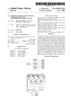
An automation system for programming appliances having
programmable controllers, programmable devices and trig
(73) Assignee: Ameritech Services, Inc.
ger devices that communicate over a communication link.
The user programs the programmable devices by placing the
(21) Appl' NO"
(22) Filed:
10/140’094
May 7, 2002
programmable controller in its training mode, activating the
trigger device to generate a trigger signed and places select
Related US, Application Data
programmable devices in their programmed state. After all
of the desired programmable devices have been put in then
programmed states, the user takes the programmable con
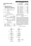
(63)
Continuation of application No. 09/602,393, ?led on
troller out of its training mode. When the programmable
Jun. 22, 2000, noW Pat. No. 6,385,495, Which is a
controller is out of its training mode, it monitors the com
continuation of application No. 09/201,296, ?led on
Nov. 30, 1998, noW Pat. No. 6,112,127, Which is a
continuation of application No. 09/746,115, ?led on
Dec. 21, 2000.
munication link for the trigger event. Upon detecting the
trigger event, the programmable controller sends messages
to the selected programmable devices instructing them to go
to their programmed state.
PROGRAMMABLE
CONTROLLER IN
TRAINING
MODE?
TRIGGER
EVENT
DETECTED?
54
RECORD TRIGGER EVENT
IN PROGRAMMABLE
CONTROLLER
B ROADOAST
MESSAGE
T
D ETECTE D?
58
RECORD BROADCAST
MESSAGE IN PROGRAMMABLE
CONTROLLER
PROGRAMMABLE
CONTROLLER OUT
OF TRAINING
TERMINATE PROGRAMMING
|
I
Patent Application Publication
12'
Feb. 13, 2003 Sheet 1 0f 13
US 2003/0033028 A1
Patent Application Publication
Feb. 13, 2003 Sheet 2 0f 13
_
_
_.: li
‘il'a
US 2003/0033028 A1
—
I
_
u
_A_/
22
SE
__@6328
"
"Iot> w
u
u
\
f
_/
u
>
Il llIi1;_lIillIi
_
_
_
_
__
_
_
M
_
/
\mmoEo_mB_?am
_$2017:me_9232
umm3m8am9a2?_
“H?zmowz?
miH
Duol !‘\mm_
u
@N _
"
_
_
_
mi
N.
Patent Application Publication
Feb. 13, 2003 Sheet 3 0f 13
3/
£\
wgzom? }i_3l2
3%
we1.
32.m5z%wo?t
‘ £w2m56g20m
m.oZkiowdm
US 2003/0033028 A1
mz_2w0zn¢A
/3)
E
ME
m
Patent Application Publication
Feb. 13, 2003 Sheet 5 0f 13
PROGRAMMABLE
US 2003/0033028 A1
Dane 5)
CONTROLLER IN
TRAINING
MODE?
TRIGGER
EVENT
DETECTED?
)4
RECORD TRIGGER EVENT
IN PROGRAMMABLE
CONTROLLER
56
BROADCAST
MESSAGE
DETECTED?
58
/
RECORD BROADCAST
MESSAGE IN PROGRAMMABLE
CONTROLLER
PROGRAMMABLE
CONTROLLER OUT
TERMINATE PROGRAMMING
Fig. 4
Patent Application Publication
Feb. 13, 2003 Sheet 6 0f 13
PROGRAMMABLE
US 2003/0033028 A1
_
CONTROLLER OUT
TRIGGER
EVENT
DETECTED?
68
/
RECALL PROGRAM STORED
‘
1N PROGRAMMABLE
5
CONTROLLER
BROADCAST PROGRAM
STORED FOR TRIGGER
EVENT DETECTED
BROADCAST
MESSAGE
DETECTED?
78
BROADCAST
MESSAGE HAVE
IGNORE
I> BROADCAST
MESSAGE
TNSTRUCTIONS FOR
PROGRAMMBLE
76
RECEIVE iNSTRUCTiONS
Patent Application Publication
Feb. 13, 2003 Sheet 7 0f 13
US 2003/0033028 A1
1 2H
W110
@[:3/
@Kj/
100-‘
/
/
18'
Fig. 6
DEPRESS TRAIN BUTTON
TO BEGIN PROGRAMMING
SUPPLY TRIG GER EVENT
BY OPENING DOOR #1
v
TURN ON LAMP #1
TURN ON LAMP #2
DEPRESS TRAIN BUTTON
TO TERMINATE PROGRAMMING
r110
Patent Application Publication
Feb. 13, 2003 Sheet 8 0f 13
US 2003/0033028 A1
DEPRESS TRAIN BUTTON
TO BEGIN PROGRAMMING
SUPPLY TRIGGER EVENT
BY TURNING ON LAMP #1
v
{
F.
9
TURN OFF LAMP #2
TURN ON LAMP #3
DEPRESS TRAIN BUTTON
TO TERMINATE PROGRAMMING
DEPRESS TRAIN BUTTON
TO BEGIN PROGRAMMING
SUPPLY TRIGGER EVENT
BY TURNING ON LAMP #1
"
TURN ON LAMP #2
v
TURN ON LAMP #3
TURN OFF LAMP #1
v
DEPRESS TRAIN BUTTON
TO TERMINATE PROGRAMMING
Fig. 10
Patent Application Publication
Feb. 13, 2003 Sheet 9 0f 13
US 2003/0033028 A1
DEPRESS TRAIN BUTTON
TO BEGIN PROGRAMMING
v
SUPPLY TRIGGER EVENT
BY TURNING SWITCH
"
TURN ON LAMP #1
Fig. 11
TURN ON LAMP #2
TURN ON LAMP #3
DEPRESS TRAIN BUTTON
TO TERMINATE PROGRAMMING
DEPRESS TRAIN BUTTON
TO BEGIN PROGRAMMING
I
SUPPLY TRIGGER EVENT BY
DEPRESSING A PUSH BUTTON
TURN OFF LAMP #1
I,
TURN ON LAMP #2
TURN OFF LAMP #3
I
DEPRESS TRAIN BUTTON
TO TERMINATE PROGRAMMING
Fil'g. 12
Patent Application Publication
I
Feb. 13, 2003 Sheet 10 0f 13
US 2003/0033028 A1
I
mm
3
O1)
3 UB5 2
1E
g/
3/ G)
B‘
E
/’[j
at! /
<‘31\
I]
0
E
/m
/
/
/
<3
Patent Application Publication
Feb. 13, 2003 Sheet 11 0f 13
230
\
JULY 9, 1996
232—
ALARM SETTING
\ DAYLlGHT
4:12 PM‘.
SET
A
A
E] H%IR kg“
240 "\
\
74
o
f COMFORT
A SET
74
242< \ECONOMY
O
V
Fig. 15
US 2003/0033028 A1
Patent Application Publication
Feb. 13, 2003 Sheet 12 0f 13
US 2003/0033028 A1
/244
EHZHEI
E1515!
IZHEIE!
EHEHZI
//244
~~244
~~244
248/
TRAIN
254
252
252
224
224
Fig. 17
Patent Application Publication
Feb. 13, 2003 Sheet 13 0f 13
US 2003/0033028 A1
256
6) TRAIN
258\
NEXT
RESET
Fig. 18
123456789012345678901234
MONDAY
{:l
APRIL 1, 1996
:I
9115 A_M.(MORE INFORMATION)»
[:l
TRAiNlNG
1
2
3
SECURlTY
4
5
6
TEST
7
8
9
0
YES
SPEAKER
LOCK
NO
(RED)
(BLUE)
Fig. 19
Feb. 13, 2003
US 2003/0033028 A1
AUTOMATION SYSTEM AND METHOD FOR THE
PROGRAMMING THEREOF
[0006]
The Echelon Corporation has built home automa
TECHNICAL FIELD
tion and industrial control apparatus based on a signaling
protocol they refer to as LonWorks that uses a netWork of
nodes each of Which has one or more microprocessors. The
[0001] An automation system for controlling the behavior
system is designed to operate in a “cooperative computing”
of an environment in response to certain events.
environment in Which the individual nodes maintain their
oWn programs. Programming of the individual nodes can be
BACKGROUND OF THE INVENTION
[0002]
Currently, automation systems Which are used to
control the behavior of an environment such as a home or
of?ce building are programmed using either a simple com
mand language or using a graphical user interface that
requires a computer With a monitor. These systems are
expensive and require substantial investment by the user in
time and energy to install and modify programming. Gen
erally to make changes in existing programs of such systems
a user must consult a user’s manual or call a programming
specialist. The overall utility of the automation system is
done by doWnloading neW softWare from a temporarily
attached lap top computer or by doWnloading softWare over
the LonWorks netWork. A similar approach has been taken
by CEBus and has been used in many custom installations
for larger homes and office buildings.
[0007] While such system eliminate the central control
unit, modifying the softWare still requires the use of a
PC-based system and usually requires the user to acquire
relatively expensive hardWare and softWare and become
pro?cient in the use of PC-based softWare.
drastically reduced because the user ?nds it dif?cult to adapt
the system to changing needs or to make additions, deletions
[0008]
or modi?cations to the programs resident in such systems.
mable and reprogrammable. It is also desirable to provide a
home automation system that can be programmed and
[0003] Home automation systems, or home management
systems as they are sometimes called, commonly provide for
control of lighting, heating and air conditioning, WindoW
shades or curtains, pool heaters and ?ltration systems, laWn
sprinklers, ornamental fountains, audio/visual equipment,
and other appliances. Home automation systems are fre
quently integrated With a home security system so that When
a ?re alarm is raised, for example, internal and external
lights Will be turned on. Security systems frequently include
lighting control and other types of home automation as an
option. Many larger homes incorporate a home theater
Which requires a certain amount of automation for conve
nient operation and this automation is often extended to
other parts of the dWelling. In farms, the automation system
Will also control outbuilding heating and lighting and Warn
of off normal conditions in automated feeding machinery
It is thus desirable to provide an automation system
that is inexpensive, easily installed, and easily program
reprogrammed by a user having little or no knoWledge or
experience in programming. It is also desirable to provide an
automation system that alloWs the incorporation of neW and
different, appliances and controllers Without the system
becoming obsolete.
SUMMARY OF THE INVENTION
[0009] According to a ?rst aspect of the present invention
there is provided a method of programming at least one
appliance to change state upon the occurrence of a trigger
event. The method includes the steps of providing at least
one programmable devices coupled to the at least one
appliance, providing a programmable controller coupled to
the programmable device Where the programmable control
from user controls and maintains a schedule of pre-pro
ler and programmable device communicate With one
another. The programmable controller has a training mode
Which, When selected, alloWs the at least one programmable
device to be programmed to change the state of the ?rst
appliance upon the occurrence of the trigger event. The user
grammed time-of-day and day-of-the Week events. Inputs to
the central control are provided by dedicated loW-voltage
Wiring, for example, from door and WindoW sensors, signals
vides a trigger event, and changes the state of the ?rst
appliance from an unprogrammed state to a programmed
and the like.
[0004] One form of automation system includes a central
control unit that monitors environmental sensors and inputs
places the programmable controller in training mode, pro
carried on poWer lines, RF signals, signals on existing
state. The user then takes the programmable controller out of
telephone Wiring and, occasionally, optical signals. The
training mode so that the ?rst appliance is noW programmed
central control unit is controlled by a program that is either
speci?cally built for the particular installation or a general
so that upon the next occurrence of the trigger event the ?rst
purpose program With a user interface that alloWs the oWner
or a technician employed by the oWner to make certain types
of modi?cations. The interfaces to these programs can be
anything from strings of digits entered on standard touch
tone keypads, for example, Home Automation Inc.’s Omni
Automation and Security System, to graphical user inter
faces, for example, the Molex “Choices” softWare.
[0005]
While the graphical user interfaces can be rela
tively easy to use, they require the presence in the home of
a personal computer and often require the system oWner to
purchase additional hardWare and softWare. Systems that
rely on touch tone keypads for input and one-and tWo-line
LCD for display are less expensive, but generally require the
user to remember or, more likely, lookup arbitrary com
mands.
appliance Will change states from its unprogrammed state to
its programmed state.
[0010]
According to a second aspect of the present inven
tion there is provided a system of programming at least one
appliance. The system includes a programmable device
coupled to at least a ?rst appliance Where the programmable
device detects the state of the ?rst appliance, and a pro
grammable controller coupled to and communicating With
the programmable device over a communication link. The
programmable controller has a training mode Which, When
selected, alloWs the programmable device to be programmed
to change the state of the ?rst appliance upon the occurrence
of the trigger event. When the programmable controller is
put in the training mode and a trigger event occurs, and the
state of the ?rst appliance is changed and the programmable
controller is taken out of the training mode, the ?rst appli
Feb. 13, 2003
US 2003/0033028 A1
ance Will change to its programmed state upon the neXt
occurrence of the trigger event.
[0011]
According to a third aspect of the present invention
there is provided a method for programming a home auto
BRIEF DESCRIPTION OF THE DRAWINGS
[0014]
FIG. 1 is a schematic of an automation system
according to a preferred embodiment of the present inven
tion.
mation system. The method includes the steps of providing
programmable devices located throughout a home. Each
programmable device is coupled to an appliance and each
[0015]
programmable device can detect the state of the appliance
coupled to it. Providing a programmable controller located
in the home and coupled to the programmable devices by a
communication link. The programmable controller has a
[0016]
training mode Which, When selected, alloWs selected pro
grammable devices to be programmed to change the state of
the appliance connected thereto. Programming selected
appliances to change from an unprogrammed state to a
programmed state by placing selected appliances in their
respective unprogrammed state, placing the programmable
controller in the training mode, providing a trigger event,
changing the states of selected appliances from their unpro
grammed state to their programmed state and taking the
programmable controller out of the training mode. The home
is noW programmed so that the neXt occurrence of the trigger
event Will cause the selected appliances to change from their
unprogrammed states to their programmed states.
[0012]
According to a fourth aspect of the present inven
tion there is provided a method of programming at least one
appliance. The method includes the steps of providing a
programmable controller coupled by a communication link
to the at least one appliance, placing the programmable
controller in the training mode, broadcasting a trigger event
over the communication link Wherein the trigger event is
received and stored by the programmable controller, chang
ing the state of the at least one appliance from an unpro
grammed state to a programmed state, deleting the change of
FIG. 1a is a schematic of an automation system
according to another preferred embodiment of the present
invention.
FIG. 2 is a block diagram of the programmable
controller shoWn in FIGS. 1 and 1a according to a second
preferred embodiment of the present invention.
[0017] FIG. 3 is a block diagram of the programmable
device shoWn in FIG. 1 according to a third preferred
embodiment of the present invention.
[0018] FIG. 3a is a block diagram of the programmable
device shoWn in FIG. 1a according to a preferred embodi
ment of the present invention.
[0019]
FIG. 4-5 are flow charts illustrating the commu
nication protocol betWeen the programmable controller and
programmable device according to a preferred embodiment
of the present invention.
[0020] FIG. 6 illustrates the front panel of a program
mable controller incorporated With a bank of sWitches
according to a preferred embodiment of the present inven
tion.
[0021] FIG. 7 illustrates the front panel of a program
mable controller incorporated With a bank of push buttons
according to a preferred embodiment of the present inven
tion.
[0022]
FIG. 8-12 are flow charts illustrating various pro
gram sequences.
state of the at least one appliance, broadcasting a message
[0023]
over the communication link indicating that the programmed
matic for a home automation system according to a preferred
embodiment of the present invention.
state of the at least one appliance Wherein the message is
received and stored by the programmable controller, and
taking the programmable device out of the training mode.
The at least one appliance is programmed to go to its
programmed state upon the occurrence of the trigger event.
[0013]
According to a ?fth aspect of the present invention
there is provided a method for automating an environment.
The method includes the steps of providing programmable
device coupled to a communication link, providing a pro
grammable controller having memory, Wherein the program
mable controller is coupled to the communication link
Wherein the programmable controller and programmable
device communicate With one another over the communi
cation link, providing a trigger device coupled to the com
munication link Wherein the trigger device and program
mable controller communicate With one another, placing the
programmable controller in a training mode, activating the
trigger device to generate a trigger signal, storing the trigger
signal in the memory of the programmable control, placing
the programmable device in a desired state, broadcasting a
message that the programmable device is in the desired state,
storing the message in the memory of the programmable
controller, taking the programmable controller out of the
training mode, monitoring the communication link for the
trigger event, detecting the trigger event, and broadcasting a
control signal over the communication link to the program
mable device to change to its desired state.
FIG. 13 is a of the Wiring and components sche
[0024] FIG. 14 illustrates the front panel of a program
mable clock according to a preferred embodiment of the
present invention.
[0025] FIG. 15 illustrates a front panel of a programmable
thermostat according to a preferred embodiment of the
present invention.
[0026] FIG. 16 illustrates a front panel of a security
interface according to a preferred embodiment of the present
invention.
[0027]
FIG. 17 is a schematic of a remote programmable
light ?xture.
[0028] FIG. 18 illustrates a front panel of a sequence
interface according to a preferred embodiment of the present
invention.
[0029] FIG. 19 illustrates a front panel of a Whole house
controller according to a preferred embodiment of the
present invention.
DETAILED DESCRIPTION OF THE
PRESENTLY PREFERRED EMBODIMENTS
[0030] FIG. 1 is a perspective vieW of an automation
system 10 according to a preferred embodiment of the
present invention. In its simplest embodiment the automa
Feb. 13, 2003
US 2003/0033028 A1
tion system 10 includes a programmable controller 12, a
programmable device 14, and a communication link 16
coupling the programmable controller 12 and the program
generated the ?rst message received by the programmable
controller after it is placed in training mode. For example, if
sible control or train button 18 to place the programmable
the trigger event is generated by an environmental sensor
coupled to the communication link 16, the trigger event may
be the detection of a movement in the ?eld of vieW of the
sensor, the opening or closing of a door or WindoW, the
controller 12 in training mode and take the programmable
controller out of training mode. Training mode refers to the
be generated by a programmable device Where the trigger
mable device 14 so that they can communicate With one
another. The programmable controller 12 has a user acces
state in Which the programmable controller 12 is in When it
is being programmed. In a preferred embodiment the user
accessible control 18 is a push doWn button Which places the
programmable controller 12 in training mode and When
pushed again to release the button takes the programmable
detection of an alarm condition. The trigger event can also
event is the change of state of the programmable device. For
example, the user may Want a second programmable device
to go to a desired programmed state every time a ?rst
controller 12 out of training mode. The user accessible
control 18 Will be referred to hereinafter as the “train
programmable device goes to a particular programmed state.
Putting the ?rst appliance in its programmed state after the
programmable controller 12 is in the training mode is the
trigger event. Generally the trigger event can be any signal
button.” Optionally, the programmable controller 12 may
broadcast over communication link 16 to the programmable
also be equipped With an indicator 20 such as an LED Which
controller 12. The trigger event is preferably the ?rst
detected signal by the programmable controller 12 after it
has been put in training mode. Various programming
sequences and trigger events Will be described hereinafter.
is illuminated When the programmable controller 12 is in
training mode and is extinguished When the programmable
controller is not in training mode. The programmable device
14, Which Will be described in detail hereinafter, broadcasts
messages to and receives messages from the programmable
[0033]
The programmable device 14 illustrated in FIG. 1
controller 12 over communication link 16.
is able to broadcast messages over the communication link
[0031] First a brief description of the operation of the
automation system 10 Will be given folloWed by a detailed
description of various preferred embodiments of the com
ponents of the automation system 10. The automation sys
over the communication link 16 to control its operation. The
programmable device 14 includes but is not limited to
tem 10 is programmed by demonstrating What should hap
pen in response to a particular event. For example, if the
automation system 10 is installed in a home, the program
mable controller 12 is preferably mounted in a 9 Wall of the
home, for example, Where the user Will have access to the
train button 18. The programmable device 14 is also located
in the home and the communication link 16 betWeen the
16 indicating a change in its state and also receive signals
appliances such as sWitches, lamps, dishWashers, curtain
controls, audio and video equipment, thermostats,
laWnsprinklers, etc.
[0034]
FIG. 1a is a perspective vieW of an automation
system 10‘ according to another preferred embodiment of the
programmable controller 12 and the programmable device
present invention. FIG. 1a is similar to FIG. 1 except that
the programmable device 14‘ is divided into a programmable
outlet 17 and an appliance 19. In a preferred embodiment,
the programmable outlet 17 is plugged into the poWer line
14 is provided by the poWer lines in the home. If the user
Wants the programmable device 14 to go to a programmed
state upon the occurrence of a particular event, i.e. a trigger
lamp, can be plugged. The programmable outlet 17 detects
a change in state of the appliance coupled thereto and
event, the user ?rst places the programmable controller 12 in
broadcasts a message over the communication link 16‘ that
its training mode by depressing the train button 18, and then
the appliance 19 has changed states. While a lamp is shoWn
as the appliance in this preferred embodiment, the present
invention is not limited to such appliances but includes other
causes a trigger signal Which Will be described hereinafter,
that is received by programmable controller 12 over the
and provides a socket into Which an appliance 19, such as a
communication link 16. The user then Walks over to the
appliances such as sWitches, dishWashers, curtain controls,
programmable device 14 he or she Wishes to be controlled
audio and video equipment, etc. The term appliance is used
by the trigger event and puts the programmable device 14 in
the desired programmed state. For example, if the program
broadly to encompass any device that can change its state at
mable device is a lamp, the programmed state may be
turning the lamp on. The user then Walks back to the
programmable controller 12 and takes it out of its training
mode using the train button 18. NoW the automation system
10 is programmed so that upon the next occurrence of the
trigger event, the programmable device 14 Will go to the
desired programmed state. A detailed description of the
communications over communication link 16 Will be
described hereinafter.
[0032] The trigger event can be generated in numerous
Ways. For example, as Will be seen hereinafter, program
mable devices 14 frequently generate messages Which can
be regarded as trigger events by the programmable control
least from one state to another.
[0035] While the particular embodiment described With
reference to FIGS. 1 and 1a have the poWer lines of a home
establishing the communication link 16, the present inven
tion is not limited to such a communication media. Other
media may be used such as RF transmissions, messages over
dedicated Wiring, messages sent as data over phone lines
using frequencies not used by voice signals, optical signals,
etc. In addition, While only one programmable device 14 is
shoWn in FIGS. 1 and 1a, a plurality of programmable
devices can be provided to communicate With one or a
plurality of programmable controllers 12 all coupled by
communication link 16. Later, a description of preferred
embodiments of the present invention applied to a home
automation system Will be described.
ler 12. In operation, the programmable controller 12 can
receive a number of messages that might be trigger events
and other messages that might be generated by the user
[0036]
putting programmable devices 14 into their programmed
controller 12 shoWn in FIGS. 1 and 1a according to a
state. The trigger event is selected as the event Which
preferred embodiment of the present invention. The pro
FIG. 2 is a block diagram of the programmable
Feb. 13, 2003
US 2003/0033028 A1
grammable controller 12 includes a transceiver 22, a micro
control is passed to block 52 Where it is determined Whether
processor 26 preferably having both RAM memory 28 and
ROM memory 30 and train button 18. The microprocessor
26 is coupled to the transceiver 22 Which in turn is coupled
link 16. If a trigger event has been detected, that trigger
event is recorded in the RAM 28 of the programmable
to the communication link 16. The transceiver 22 receives
messages from the communication link 16 and sends mes
sages over the communication link 16. The train button 18
is coupled to the microprocessor 26 and places the program
mable controller 12 either in or out of training mode. The
programmable controller 12 has an address identi?ed With it
Which may be stored in ROM 30 or alternatively, an address
selector 32, coupled to the microprocessor 26, can be
provided to alloW the address of the programmable control
ler 12 to be selected.
[0037] FIG. 3 is a block diagram of the programmable
device 14 shoWn in FIG. 1 according to a preferred embodi
ment of the present invention. The programmable device 14
includes a transceiver 34 appliance electronics 35, and a
microprocessor 40 preferably having both RAM memory 42
and ROM memory 44. The microprocessor 40 is coupled to
the transceiver 34, and appliance electronics 35. The trans
ceiver 34 is coupled to the communication link 16 to receive
and broadcast messages over the communication link 16.
The programmable device 14 has an address identi?ed With
it Which may be stored in ROM 42 or alternatively, an
address selector 44, coupled to the microprocessor 40, can
be provided to alloW the address of the programmable
device 14 to be selected.
[0038] In the preferred embodiment illustrated in FIG. 3,
the programmable device 14 is like that shoWn in FIG. 1 in
Which it is integrated into the appliance itself
[0039] FIG. 3a is a block diagram of the programmable
device 14‘ shoWn in FIG. 1a according to a preferred
embodiment of the present invention. The programmable
device 14‘ includes a transceiver 34‘, a control relay 36, a
load detector 38, and a micro-processor 40‘ preferably
having both RAM memory 42‘ and ROM memory 44‘. The
microprocessor 40‘ is coupled to the transceiver 34‘, control
relay 36 and load detector 38. The transceiver 34‘ is coupled
to the communication link 16 to receive and broadcast
messages over the communication link 16. The load detector
38‘ is coupled to an appliance 19 (see FIG. 1a). The
programmable device 14‘ has an address identi?ed With it
Which may be stored in ROM 42 or alternatively, an address
selector 44‘, coupled to the microprocessor 40‘, can be
provided to alloW the address of the programmable device
14‘ to be selected.
[0040] In the preferred embodiment illustrated in FIG. 3,
the programmable device 14‘ is like that shoWn in FIG. 1a
Which includes an outlet that is plugged into the poWer line
and provides a socket into Which the appliance 19, such as
a lamp, for example, can be plugged into. In such an
embodiment, the load detector 38 detects a change in state
of the appliance coupled to the programmable device 14‘, i.e.
the appliance begins draWing poWer or ceases draWing
a trigger event has been detected over the communication
controller 12 in block 54. If a trigger event has not been
detected, the programmable controller 12 Waits for the
detection of a trigger event.
[0042] After the trigger event has been detected and
recorded, control is passed to block 56 Where it is deter
mined Whether a message has been broadcast by a program
mable device 14 over the communication link 16. If a
message is detected, control is passed to block 58 Where the
broadcast message is recorded in the RAM 28 of the
programmable controller 12. If a broadcast message has not
been detected, the programmable controller 12 Waits for a
broadcast message. After a broadcast message has been
detected and recorded, control is passed to block 60 Where
it is determined Whether the programmable controller 12 has
been taken out of training mode. If it has, control is passed
to block 62 and the programming is terminated. If not,
control is passed back to block 56 Where the programmable
controller 12 Waits for another message to be broadcast by
another programmable device. This cycle continues until the
programming has been terminated.
[0043] The recording of the trigger event and broadcast
messages by the programmable controller creates a program
stored by the programmable controller 12. Of course many
programs formed by trigger events and the broadcast mes
sages associated thereWith can be stored by the program
mable controller. In FIGS. 1 and 1a only one programmable
device 14 is shoWn, hoWever, it is to be understood that a
plurality of programmable devices can be coupled to the
communication link 16 in Which case the programmable
controller 12 may receive more than one broadcast message.
In particular, according to a preferred embodiment of the
present invention, the trigger signal Will have associated
With it a unique identi?er Which Will be recorded by the
programmable device 12. The message(s) broadcast by the
programmable device(s) Will each have associated With it
the programmable device’s unique address, preferably a
byte or tWo in length, folloWed by a message. The message
of the broadcast signal may specify that the device has been
turned on or off or that a particular percentage of energy is
being draWn, for example. In addition, particularly for the
embodiment shoWn in FIG. 1, the message includes instruc
tions Which Will be broadcast back to the programmable
device to cause it to mimic the action that Was just taken.
This message Will be broadcast back to the programmable
device by the programmable controller upon the next occur
rence of the trigger event When the programmable controller
12 is out of training mode. This is particularly useful When
the programmable device 14 is like that shoWn in FIG. 1
because the programmable controller 12 does not have to
knoW anything about the con?guration of the programmable
poWer or the amount of poWer the appliance is draWing.
device 14 The programmable device 14 provides its oWn
instruction in the message it broadcasts to the programmable
controller.
[0041] The communication betWeen the programmable
[0044]
controller 12 and the programmable device Will noW be
described With reference to the How chart shoWn in FIG. 4.
At block 50 it is determined Whether the programmable
controller 12 has been put in training mode. If it has not,
control is passed to block 64 shoWn in FIG. 5. If it has then
accommodate neW types of appliances and controllers. For
example, suppose that at some future time it became popular
to install lighting Where the user could control not only the
This alloWs the automation system 10 to easily
intensity of a programmable light ?xture (on, off and various
dimming levels), but also the color of the light. For existing
Feb. 13, 2003
US 2003/0033028 A1
automation systems, in order to add color control it Would be
nication link checks the program broadcast by the program
necessary for system controllers to receive neW program
mable controller to see if any of the messages contained
therein are for it.
ming that at the minimum expanded the message set de?n
ing control of lighting from one that referred only to
intensity to one that speci?ed color and intensity.
[0045] In a preferred embodiment of the present invention
a simpler and more general solution to the problem of adding
neW devices to be controlled Without making any modi?
cations of the existing system components exists. For
example, in the case of a lighting appliance that alloWs the
user to adjust both color and intensity, a user control panel
could be provided so that the user could use one control to
adjust intensity and another control to adjust color of the
indirect lights in a room. Using programming methods
previously discussed, the user could then program the pro
grammable controller to provide a soft “White” indirect light
When a small table lamp Was turned on and to provide bright
White light When a particular ?oor lamp Was illuminated. To
make this programming possible Without making any
changes in the programmable controller, the neW lighting
?xture Would be a programmable device that Would broad
cast a message to the programmable controller that con
tained Within that message an instruction that should be sent
back to the lighting appliance in order to duplicate the
setting the user had selected from the control panel. The
programmable controller stores the message that should be
sent to the neW lighting ?xture, and in the future When the
trigger event Was detected it Would direct the stored message
to the neW lighting appliance. The programmable controller
doesn’t need to “knoW” anything about the operation of this
neW programmable device and doesn’t even need to knoW it
is a light.
[0046] When the programmable controller 12 is out of its
training mode, it monitors the communication link 16 for
recogniZable trigger events. FIG. 5 is a How chart illustrat
ing the communications over communication link 16 When
the programmable controller 12 is out of its training mode.
At block 64 it is determined Whether the programmable
controller 12 is out of its training mode. If it is not, control
of the program is transferred to block 50 as shoWn in FIG.
4. If it is, control is passed to block 66 Where it is determined
Whether a trigger event has been detected. If one has not,
control is returned to block 66 Where the programmable
controller 12 Waits for the detection of a trigger event. Once
a trigger event has been detected control is passed to block
68 Where the program stored in the RAM 28 of the pro
grammable controller 12, associated With the particular
trigger event detected, is recalled. Then at block 70, the
program stored in RAM 28 of the programmable controller
12 is broadcast over communication link 16. The program
[0047] Signaling protocols such as X-lO (a proprietary
protocol of the X-10 Corporation), CEBus (an EIA standard
backed by an industry consortium) or Lon Works (a standard
oWned and maintained by the Echelon Corporation) may be
used for the communication protocol over communication
link 16.
[0048] The programmable controller may be incorporated
into more complex systems depending upon the particular
application to Which it Will be subjected. FIG. 6 illustrates
a programmable controller 12‘ incorporated With a bank of
sWitches 100 according to a preferred embodiment of the
present invention. FIG. 7 illustrates a programmable con
troller 12“ incorporated With a bank of push buttons 110
according to a preferred embodiment of the present inven
tion.
[0049] The programmable controllers 12‘ and 12“ shoWn
in FIGS. 6 and 7 respectively are particularly useful for tWo
types of programming. A ?rst type, Which Will be referred to
as “Type I” programming, causes programmable devices
coupled over a communication link 16 to the programmable
controller and selected to be programmed to all go to the
same state When the trigger event occurs. For the simplest
variety of Type I programming, all of the selected program
mable devices have just tWo states; for example, on and off.
The trigger event also has tWo states, for example, on and
off. When the trigger event is put in its on state, all of the
selected programmable devices go to their on state. When
the trigger event is put in its off state, all of the selected
programmable devices go to their off state. Of course, the
programmable devices and trigger event may have more
than tWo states. For example, suppose that the trigger event
is supplied by a programmable dimmer sWitch and the
selected programmable devices are light ?xtures attached to
the programmable dimmer sWitch. For Type I programming,
all of the lighting ?xtures Would respond to changes in the
setting of the trigger dimmer in the same Way. The program
mable devices and trigger event do not have to be identical
in state but they do have to be congruent in the sense of
having operational states that can be mapped onto each
other. For example, suppose there are three programmable
devices 14‘ according to the preferred embodiment shoWn in
FIG. 1a Where each appliance 19 is a lamp. If the user Wants
to program all of the lamps to turn on based upon the
occurrence of a trigger event, the user performs the folloW
ing sequence:
mable devices 14 coupled to the communication link 16
listen for broadcasted messages. At block 72 each program
mable device 14 coupled to communication link 16 detects
[0050]
Whether a message has been broadcast. Control is then
[0051] supply a Type I type trigger event (i.e.,
passed to block 74 Where it is determined Whether the
program broadcast includes any message for particular pro
grammable devices. If it does, control is passed to block 76
press the train button 18‘ to place the program
mable controller 12‘ in its training mode to com
mence programming;
depress one of the bank of sWitches 100)
[0052]
turn lamp 1 on;
their unique address With the addresses in the broadcast
[0053]
turn lamp 2 on;
program. If it recogniZes its address, the programmable
[0054] turn lamp 3 off; and
Where the programmable devices detect this by matching
device receives its designated message in the program and
executes the instructions associated With that message. If
not, control is passed to block 78 Where the message is
ignored. Each programmable device coupled to the commu
[0055] deactivate the user control to take the pro
grammable controller out of training mode to con
clude programming.
Feb. 13, 2003
US 2003/0033028 A1
[0056] NoW, upon the next occurrence of the trigger event
When the programmable controller is out of its training
mode, lamps 1, 2 and 3 Will all turn on. The actual state of
since for the purpose of this training sequence Lamp 1 is a
trigger event and all trigger events subsequent to the occur
rence of the ?rst trigger event are ignored. In other appli
the appliances during programming is immaterial, the
cations it may not be appropriate to ignore subsequent
important feature is that the user touched the appliance
trigger events. The sequence shoWn in FIG. 11 programs the
home to turn Lamps 1, 2 and 3 on every time one of the bank
during programming regardless of Whether the appliance
Was turned on or off. The bank of sWitches 100 shoWn in
referred to as “Type II” programming, associates discrete
events With speci?c commands to be sent to the program
of sWitches 100 shoWn in FIG. 6 is turned on. Because one
of the bank of sWitches 100 Was used as the trigger event, it
Was assumed that Type I programming Was implemented
Which cause all of the selected appliances to go to the same
state as the trigger event regardless of their actual state
mable devices. For Type II programming the state of the
during programming. Alternatively, the sequence shoWn in
appliance during programming is material. Thus, if the
FIG. 12 programs the house to turn Lamps 1 and 3 off and
Lamp 2 on every time one of the push buttons 110 shoWn in
FIG. 7 is depressed. Even though the same steps Were
performed after the trigger event as occurred in FIG. 11,
because one of the push buttons 110 of the programmable
Was used as the trigger event it Was assumed that Type II
programming Was implemented Which causes all of the
selected appliances to go to their individual programmed
FIG. 6 are particularly useful in such an application.
[0057] The second type of programming, Which Will be
above sequence Was programmed using Type II program
ming, lamps 1 and 2 Would turn on and lamp 3 Would turn
off upon the occurrence of the trigger event. The bank of
push buttons 110 shoWn in FIG. 7 are particularly useful for
Type II programming.
[0058]
The determination of Whether Type I or Type II
programming is taking place is arbitrary and the present
invention is not limited to the particular examples given.
Whether the programming is of Type I or Type II is inferred
from the trigger event and from What programmable devices
that are to be controlled by that trigger event. If the trigger
event is supplied by an on/off sWitch and if the appliances to
states. As already described the assumptions made With
respect to Type I and Type II programming are arbitrary and
the present invention is not limited to the particular
eXamples given.
[0061]
These are but some of the programming sequences
event is supplied by a momentary contract device or the
that can be implemented using the programmable controller
and programmable devices according to the present inven
tion. The present invention, hoWever, is not limited to these
opening of a door, then it may be assumed that Type II
particular sequences.
programming is being performed. If the trigger event is
supplied by an appliance Whose state is reversible, the lamp
[0062] Adding, changing or deleting eXisting programs is
be controlled all have on and off states, it may be assumed
that Type I programming is being performed. If the trigger
can be turned either on or off, it may be assumed that either
Type I or Type II programming is being performed. In a
preferred embodiment it is assumed that the programming is
Type II. While particular assumptions have been described
linking certain events to Type I or Type II programming,
other embodiments, Which Would be obvious to those of
ordinary skill in the art in light of the teachings of the present
invention, may be implemented. In a preferred embodiment,
the programmable controller decides the programming
mode.
also simply implemented. In a preferred embodiment, if the
system has learned a response to a particular trigger event,
to delete responses associated With that particular trigger
event one need only put the programmable controller in the
training mode, supply the particular trigger event and then
take the programmable controller out of the training mode.
To clear all programming one need only put the program
mable controller in the training mode and then directly take
the programmable controller out of the training mode. Of
course, in a particular application if the risk of inadvertently
erasing programming outWeighs the convenience of being
[0059] The programmable controllers and programmable
devices according to the preferred embodiments of the
present invention alloW a user to create a program by a
able to “start over,” the designer could elect to not imple
ment the “erase all” function, to require the user to perform
the “erase all” action tWice in succession before it took
simple, program by demonstration technique. No knoWledge
effect, or even to provide a separate “delete” button that Was
of programming is needed and creating, modifying or delet
ing programs can be simply implemented by the user. The
protected from accidental manipulation.
user simply physically demonstrates What is to occur upon
the detection of a trigger event.
[0060]
FIGS. 8-12 are How charts illustrating eXamples of
steps used to program various sequences in response to
various trigger events. It is assumed that the programmable
controller and programmable devices are located in a home
automation system for all of the sequences shoWn in FIGS.
8-12. The sequence shoWn in FIG. 8 trains the house to turn
Lamp 1 on and Lamp 2 off When a door is opened. The
sequence shoWn in FIG. 9 causes Lamp 2 to be turned off
and Lamp 3 turned on Whenever Lamp 1 is turned on. In this
case turning Lamp 1 on is the trigger event. The sequence
shoWn in FIG. 10 programs the house to turn Lamp 2 and
Lamp 3 on When Lamp 1 is turned on. In a preferred
embodiment the last event, turning Lamp 1 off, is ignored
[0063] The programmable controllers and programmable
devices according to the preferred embodiments already
described can be incorporated into a larger system to sup
port, for eXample, home automation. FIG. 13 is a schematic
of the Wiring and components for a home automation system
according to a preferred embodiment of the present inven
tion. The automation system 200 preferably includes the
folloWing components: a ?rst programmable controller 202,
a plurality of programmable devices 204, a second program
mable controller 206, a plurality of Wall sWitches 208, a
programmable clock 210, a programmable light ?xture 212,
a programmable thermostat 214 coupled to a HVAC inter
face 216, a security interface 218 and a security panel 220,
and a plurality of environmental sensors 222. As Will be
described, all of these components communicate With one
another preferably over the poWer lines 224 of the house in