1
YX GoIP User Manual
YX
GoIP User Manual
YX Tech
12/21/2012
第i页
YX GoIP User Manual
CONTENT
1
INTRODUCTION ........................................................................................... 1
1.1
1.2
2
EQUIPMENT INFORMATION ....................................................................... 2
2.1
2.2
2.3
2.4
3
Network Setup.....................................................................................................4
Equipment IP Address ........................................................................................4
Equipment Connection ........................................................................................4
LED Indicators.....................................................................................................5
WEB SETTINGS ........................................................................................... 6
4.1
4.2
4.3
4.4
4.5
4.6
4.7
4.8
4.9
5
Appearance .........................................................................................................2
Hardware.............................................................................................................2
Software ..............................................................................................................3
Function and Features ........................................................................................3
EQUIPMENT INSTALLATION ...................................................................... 4
3.1
3.2
3.3
3.4
4
Overview .............................................................................................................1
Glossary ..............................................................................................................1
Login ...................................................................................................................6
Basic Settings .....................................................................................................7
SIP Protocol ........................................................................................................8
GoIP Settings .................................................................................................... 10
4.4.1 Port Settings ............................................................................................... 10
4.4.2 IMEI Settings .............................................................................................. 12
4.4.3 SMS Operation ........................................................................................... 14
4.4.4 Lock/Switch Card ........................................................................................ 15
4.4.5 AT Command .............................................................................................. 18
4.4.6 Billing .......................................................................................................... 19
Application Settings........................................................................................... 22
4.5.1 Phone Book ................................................................................................ 22
4.5.2 Dial Pattern ................................................................................................. 24
4.5.3 Dial Prefix Manipulation .............................................................................. 24
4.5.4 Local Billing ................................................................................................. 25
Advanced Settings ............................................................................................ 26
4.6.1 Network....................................................................................................... 26
4.6.2 Voice and Codec ........................................................................................ 27
4.6.3 Analog Port ................................................................................................. 28
System Settings ................................................................................................ 31
4.7.1 User Management ...................................................................................... 31
4.7.2 Remote Management ................................................................................. 32
4.7.3 System Update ........................................................................................... 33
Running Status.................................................................................................. 34
4.8.1 Port Status .................................................................................................. 34
4.8.2 Call Status .................................................................................................. 35
4.8.3 System Status ............................................................................................. 36
4.8.4 Call Statistics .............................................................................................. 37
Save and Reboot .............................................................................................. 38
TYPICAL USED SCENARIO ....................................................................... 39
YX Tech
12/21/2012
第 ii 页
YX GoIP User Manual
5.1
5.2
6
FAQ ............................................................................................................. 41
6.1
7
Landing from IP to Mobile Network ................................................................... 39
Access from Mobile Network to IP .................................................................... 40
How to designate a port for outbound call ......................................................... 41
APPENDIX 1 ............................................................................................... 43
YX Tech
12/21/2012
第 iii 页
YX GoIP User Manual
1 Introduction
1.1 Overview
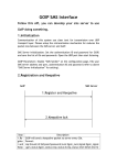
A VoIP GSM Gateway (GoIP Gateway) is a device which reduces costs when
calling from a fixed telephone line to mobile network. It enables direct routing
between IP, digital, analog and mobile networks.
GoIP Gateway is now used more and more for telephone carriers to land their IP
calls to mobile network. In those areas where fixed line services are unavailable
or much more expensive than the mobile cost, GoIP Gateway is an irreplaceable
alternative.
The following figure shows a basic topology of GoIP Gateway usage.
Figure 1.1
1.2 Glossary
VoIP:
Voice over Internet Protocol.
SIP:
Session Initial Protocol.
DTMF: Dual Tone Multiple Frequency.
IMEI:
International Mobile Equipment Identity.
LCR:
Least Cost Routing.
USSD: Unstructured Supplementary Service Data.
GSM:
Global System Communications.
CDMA: Code Division Multiple Access.
WCDMA: Wideband Code Division Multiple Access.
YX Tech
12/21/2012
1
YX GoIP User Manual
2 Equipment Information
2.1 Appearance
The following figure shows the front view of YX GoIP Gateway.
Figure 2.1: Front View
The following figure shows the rear view of YX GoIP Gateway.
Figure 2.2: Rear View
2.2 Hardware
The following table shows the hardware information for YX GoIP Gateway.
CPU
KSZ 8695
Memory
YX Tech
12/21/2012
2
YX GoIP User Manual
Media DSP
Power Supply
100-240V AC, 50 ~ 60 Hz
Module:
GSM/CDMA/WCDMA serials
LAN/WAN
Serial Port
Antenna
Card Slot
Dimensions
z
z
z
z
Weight
2.5 kg
Working
Environment
z
z
Rack mountable 1U chassis(compatible with 19’’ Rack)
Width: 482mm
Height: 44mm
Depth: 210mm
Temperature: 0 ~ 50 ℃
Humidity: 10% ~ 90%
2.3 Software
The following table shows the software information for YX GoIP Gateway.
OS
Embedded Linux OS
Web Server
Built-in Http Server
Firmware
SIP Client
DHCP Client
DHCP Server
PPPoE
2.4 Function and Features
This chapter introduces the overall function and features of YX GoIP Gateway.
¾ Hot-line call
¾ Dial pattern
¾ Dial prefix manipulation
¾ Phone book
¾ CDR
¾ White list
YX Tech
12/21/2012
3
YX GoIP User Manual
3 Equipment Installation
This chapter describes how to install a new GoIP Gateway to a physical network
environment, how to initialize it and start it in a proper way.
3.1 Network Setup
Network is a prerequisite to install GoIP Gateway. The following figure shows the
topology of LAN with a VoIP Gateway connected.
Note: WAN Port will be used to connect GoIP Gateway to the LAN.
3.2 Equipment IP Address
The default IP of GoIP Gateway WAN port is 192.168.1.67, while the default LAN
port IP is 192.167.1.1.
3.3 Equipment Connection
Follow the steps below to install the GoIP Gateway to LAN.
1) Fix the antenna to the GoIP Gateway. (Optional)
YX Tech
12/21/2012
4
YX GoIP User Manual
2) Insert SIM card(s) to slots.
3) Connect an Ethernet Cable to the WAN port of GoIP Gateway. The other end
of the Ethernet Cable should be connected to LAN route or switch.
4) Connect an Ethernet Cable to the LAN port of GoIP Gateway. The other end
of the Ethernet Cable should be connected to PC or other network device.
(Optional)
5) Plug in the GoIP Gateway.
3.4 LED Indicators
There are a set of LED lights in the front of GoIP Gateway. Lights will be on or
glittering when the GoIP Gateway is power on and running. The following table
describes various meanings of status corresponding to LED lights in different
display color.
Power
It indicates whether the system is running or not.
Run x
SW x
YX Tech
12/21/2012
5
YX GoIP User Manual
4 Web Settings
This chapter describes how to set up GoIP Gateway through Web Page. There is
a built-in web server which can be accessed at URL: http://GATEWAY_IP/, while
GATEWAY_IP is the WAN IP address of the GoIP Gateway, such as
192.168.1.67.
As an example, the following introduction will base on the GoIP Gateway with
WAN IP 192.168.1.67.
4.1 Login
Open web browser and access URL http://192.168.1.67/. The default login page
will be displayed as following.
The default login account and password are:
Account
root
Password
root
It is recommended to use IE or FireFox to access the web pages. After
successfully logged in, the main page to set Gateway is as following:
YX Tech
12/21/2012
6
YX GoIP User Manual
4.2 Basic Settings
Basic Settings will be described in this paragraph. The most frequently modified
parameters and most of the individual parameters are listed in this page.
SIP Server Settings is for SIP communication with IP network. Fields are
specified as following:
¾ Protocol Mode: Specify SIP client working mode. Option values are
YX Tech
12/21/2012
7
YX GoIP User Manual
Registration/Point-to-Point. If set to Registration, SIP client will send
registration messages to SIP server.
¾ Encryption Method: Specify the encryption method for messages between
SIP server and SIP client.
¾ SIP Server IP: Specify the IP of SIP server.
¾ SIP Server Port: Specify the port of SIP server.
¾ Phone Number: Specify the caller phone number for SIP client. It can also be
regarded as the SIP port number which can be called.
¾ Account: Specify the SIP account for registration.
¾ Password: Specify the SIP password for registration.
Note: The settings of Phone Number, Account and Password are globally active.
They will apply to all SIP ports settings in SIP Protocol page.
4.3 SIP Protocol
SIP Protocol Settings will be described in this paragraph. It mainly targets to set
up parameters related to SIP server, SIP account and SIP password for SIP
registration.
The screenshot below shows the operation mode to set SIP running parameters.
Fields are specified as following:
¾ Protocol Mode: It is the same as that in Basic Settings. The modification
here will also apply to Basic Settings page.
¾ Encryption Mode: It is the same as that in Basic Settings. The modification
here will also apply to Basic Settings page.
¾ SIP Server: Specify the domain or IP of the SIP Server.
¾ SIP Server Port: Specify the port of the SIP Server.
YX Tech
12/21/2012
8
YX GoIP User Manual
¾ Primary Proxy IP: Specify the primary proxy IP.
¾ Secondary Proxy IP: Specify the secondary proxy IP.
¾ Expiration Period: Specify the expiration period for registration.
¾ Local Port: Specify the local port used to register to SIP server.
¾ Multiple Port Support: Specify whether support to register to SIP server with
different SIP Account.
¾ Phone Number Registration: Specify whether enable phone number
registration or not. If set to Enabled, the Phone Number and Account can be
different when registering to SIP Server. If set to Disabled, the Phone
Number must be the same as the Account when registering, otherwise, the
registration will fail.
¾ Receive All Call: Specify whether enable to receive all calls or not.
The screenshot below shows the operation mode to SIP Accounts.
If a default Phone Number, Account and Password is already set in Basic
Settings page, all the inputs here can be left empty and the default setting will
apply to all the SIP accounts. For example, if an account GOIP-03 is set with
password 888888 in Basic Settings page and all the SIP accounts here are left
empty, the combination of GOIP-03 and 888888 will be used for all SIP accounts
to register to SIP Server.
There are two ways to overwrite the default SIP account setting in Basic Settings
page.
1) Assign an account and password to Port 1 and leave empty for other Ports.
Settings of Port 1 can also be applied to all the other Ports automatically. This
is for short to set Account and Password if all the Ports use the same value.
2) Assign account and password to certain Port(s). The value of account and
password can be various. In this scenario, only the Ports assigned with
account and password will register to SIP Server.
YX Tech
12/21/2012
9
YX GoIP User Manual
4.4 GoIP Settings
GoIP settings include:
¾ Port Settings
¾ IMEI Settings
¾ SMS Operation
¾ Lock/Switch Card
¾ AT Command
¾ Billing
These sub topics will be introduced separately below.
4.4.1 Port Settings
The screenshot below shows the operation mode to set GoIP port properties.
The columns are specified as following:
¾ Port No: The GoIP Gateway mobile port. Each port contains one or more
card slots. Port No starts from 1 to 8.
¾ Mobile Base: Specify the mobile base.
¾ Provider: Specify the provider.
¾ Input Volume: Specify the input voice volume of this port.
¾ Output Volume: Specify the output voice volume of this port.
YX Tech
12/21/2012
10
YX GoIP User Manual
¾ IMEI: Specify the IMEI of this port. Any card in this port will use this specified
IMEI to communicate with mobile base.
The screenshot below shows the operation mode to set GoIP port application
feature.
The columns are specified as following:
¾ Port No: The GoIP Gateway mobile port. Each port contains one or more
card slots. Port No starts from 1 to 8.
¾ Main Access: Specify whether the current port is used for access or not. If
set to Enable, any call made to the card in this port will be redirected to the
phone number on any other idle port which is not set as a main access. The
any other idle port may be either on the same GoIP Gateway or on another
GoIP Gateway which keeps reporting its port status to a Notification Server.
¾ Check Balance: Specify whether need to check card balance.
¾ Card Number: Specify the card number.
¾ Balance: Specify the balance of the card.
¾ SMS Forward To: Specify a receiver to which the SMS, which is sent to the
card on this port, will be forwarded. The country code must be prefixed, for
example, 8613512345678, while the string 86 stands for the country code of
China and 13512345678 is the China Mainland mobile phone number.
¾ SMS Center: Specify the code of SMS Center.
The screenshot below shows the operation mode to set GoIP port notification
YX Tech
12/21/2012
11
YX GoIP User Manual
feature.
Fields are specified as following:
¾ Enable or Not: Specify whether enable status notification or not.
¾ Server IP: Specify the IP of server to which the notification is sent to.
¾ Server Port: Specify the port of server to which the notification is sent to.
¾ Expiration Period: Specify the expiration period to send status notification
message.
4.4.2 IMEI Settings
The screenshot below shows the operation mode to set IMEI for each card
inserted in GoIP Gateway port.
Fields are specified as following:
¾ Port No: The GoIP Gateway mobile port. Each port contains one or more
card slots. Port No starts from 1 to 8.
YX Tech
12/21/2012
12
YX GoIP User Manual
¾ IMEI A: Specify the IMEI for card A of the port.
¾ IMEI B: Specify the IMEI for card B of the port.
¾ IMEI C: Specify the IMEI for card C of the port.
¾ IMEI D: Specify the IMEI for card D of the port.
The specified IMEI, instead of the default IMEI of the card, will be used for the
corresponding card to communicate with mobile base.
The screenshot below shows the operation mode to set Dynamic IMEI for each
card of the designated port. A group of IMEIs which are increased by 1 in
numeric sequence can be set for one or all card(s) on one or all GoIP Gateway
mobile port(s). If a card on a port is assigned with a group of IMEIs, it will
randomly use any of the IMEI in group to communicate with mobile base.
Add New
Click button Add New to expand the data input area to add new data. Fields are
specified as following:
¾ Data status: Mark the status of current data record. Option values are
Add/Edit. Value Add means the data is new while value Edit means the data
is old.
¾ Ports: Specify the port(s) on which the IMEI is added or modified. Option
value * means that the IMEI applies to all ports.
¾ Slots: Specify the card(s) on which the IMEI is added or modified. Option
value * means that the IMEI applies to all cards inserted in the selected ports
specified by Ports.
¾ IMEI Start: Specify an initial IMEI value for the IMEI group.
¾ IMEI Size: Specify the size of the IMEI group.
Click button Submit on the right to save the new data record.
YX Tech
12/21/2012
13
YX GoIP User Manual
Edit
All the records are displayed in list. Two operations are provided on the right of
each record. Click Edit to expand the current data record to Data Detail Area
which is above the Data List.
Click button Submit on the right to save the old data record.
Delete
Click Delete on the right of each record to delete the current record. A message
box will be popped for delete confirmation.
4.4.3 SMS Operation
The screenshot below shows the operation mode to set SMS.
Fields are specified as following:
¾ Send to Server: Specify whether need to enable the functionality of sending
SMS to server.
¾ Server IP: Specify the IP of server to which the SMS is sent. If set to empty,
the SMS will be sent to SIP server.
¾ SMS Coding: Specify the SMS coding when SMS is sent to through SIP
protocol.
The screenshot below shows the operation mode to send SMS through the GoIP
Gateway.
YX Tech
12/21/2012
14
YX GoIP User Manual
1) Select a module. The module here means GoIP mobile port and the SMS is
sent out through the card which is in service on this port.
2) Input the receivers separated by semi-colon.
3) Input SMS content and click button Send to send out the SMS.
Field Received SMS is used to display the last response of the SMS sent out, if
the response is not empty.
Field Successful SMS Number records down the total number of SMS which is
successfully sent out. Field Failed SMS Number records down the total number
of SMS which is sent failed.
4.4.4 Lock/Switch Card
The screenshot below shows the operation mode to set globally for card lock
and switch.
Fields are specified as following:
YX Tech
12/21/2012
15
YX GoIP User Manual
¾ Smart Check: Specify whether enable the smart check for cards in card slot
or not. If set to Enabled, those card slots without card inserted will be
skipped when system is scanning for available cards.
¾ SMS Receiver for Warning: Specify the receiver mobile number to receive
the warning SMS for card lock or switch.
The screenshot below shows the operation mode to set conditions for locking
card and switching card.
Fields are specified as following:
¾ Enable or Not: Specify whether enable the periodic checking or not. If set to
Enable, system will check the card running time periodically. If the
continuous running time reaches or exceeds the specified Period value, this
card will be locked and the next card will come into service.
¾ Warning SMS: Specify whether need to send warning SMS when the card is
locked.
¾ Period: Specify the period to check.
¾ Locking Duration: Specify how long the card will be locked.
The following is to set condition of accumulated call duration.
Fields are specified as following:
¾ Enable or Not: Specify whether enable this condition. If set to Enable, the
accumulated call duration will be used as a condition for system to check.
¾ Warning SMS: Specify whether need to send warning SMS when the card is
locked.
¾ Accumulated Duration: Specify the max running duration of the card. If the
accumulated running duration reaches or exceeds this value, the card will be
locked if this condition is enabled.
¾ Locking Duration: Specify how long the card will be locked.
YX Tech
12/21/2012
16
YX GoIP User Manual
The following is to set condition of accumulated bridges.
Fields are specified as following:
¾ Enable or Not: Specify whether enable this condition. If set to Enable, the
accumulated number of bridges will be used as a condition for system to
check.
¾ Warning SMS: Specify whether need to send warning SMS when the card is
locked.
¾ Accumulated Bridges: Specify the max number of bridges on this card. If the
accumulated number of bridges reaches or exceeds this value, this card will
be locked if this condition is enabled.
¾ Locking Duration: Specify how long the card will be locked.
The following is to set condition of accumulated calls.
Fields are specified as following:
¾ Enable or Not: Specify whether enable this condition. If set to Enable, the
accumulated calls will be used as a condition for system to check.
¾ Warning SMS: Specify whether need to send warning SMS when the card is
locked.
¾ Accumulated Calls: Specify the max number of calls on this card. If the
accumulated number of calls reaches or exceeds this value, this card will be
locked if this condition is enabled.
¾ Locking Duration: Specify how long the card will be locked.
The following is to set condition of consecutive failed calls.
YX Tech
12/21/2012
17
YX GoIP User Manual
Fields are specified as following:
¾ Enable or Not: Specify whether enable this condition. If set to Enable, the
accumulated number of failed calls will be used as a condition for system to
check.
¾ Warning SMS: Specify whether need to send warning SMS when the card is
locked.
¾ Accumulated Failure: Specify the max number of consecutive failed calls on
this card. If the number of consecutive failed calls reaches or exceeds this
value, the card will be locked if this condition is enabled.
¾ Locking Duration: Specify how long the card will be locked.
The following is to set condition of consecutive short calls.
Fields are specified as following:
¾ Enable or Not: Specify whether enable this condition. If set to Enable, the
accumulated short calls will be used as a condition for system to check.
¾ Warning SMS: Specify whether need to send warning SMS when the card is
locked.
¾ Accumulated Short Calls: Specify the max number of consecutive short calls
on this card. If the number of consecutive short calls reaches or exceeds this
value, the card will be locked if this condition is enabled.
¾ Short Call Duration: Specify the call duration to recognize a short call. Any
call whose duration is less than this value will be regarded as an short call.
¾ Locking Duration: Specify how long the card will be locked.
4.4.5 AT Command
The screenshot below shows the operation mode to send AT command to GoIP
Gateway.
YX Tech
12/21/2012
18
YX GoIP User Manual
The module here means the GoIP mobile port.
Button Restart is used to restart this module.
Button Stop is used to stop this module.
Button Start is used to start this module.
Button Call is used to dial out through the selected module manually.
For the USSD command, please refer to the local carrier standard.
For AT command, please refer to appendix 1.
Field Command Response is used to display the response of last command.
After send a command, a re-enter of this page is needed to see the command
response.
4.4.6 Billing
The screenshot below shows the operation mode to set GoIP billing. A smart
billing server for mobile port is embedded in GoIP Gateway.
Fields are specified as following:
¾ GoIP Billing: Specify whether enable GoIP billing or not. If set to Enabled,
system will bill the outbound calls for the port which has been assigned with
billing tariffs.
¾ Billing Type: Specify the type to get balance through USSD. Option values
are International/Internal/Local Net/Other. Each optional value maps to the
corresponding USSD Keyword in USSD Query Keyword List. The balance is
checked base on the USSD keyword which is mapped by this selected
YX Tech
12/21/2012
19
YX GoIP User Manual
choice. This field takes effect only when both GoIP Billing and USSD Check
are set to Enabled.
¾ USSD Check: Specify whether enable to get balance through USSD check
or not. This field takes effect only when GoIP Billing is set to Enabled.
¾ Save Balance: Specify whether need to save the current balance to card
periodically. If set to Enabled, the balance will be updated to card periodically
or after a call is released.
¾ Period: Specify the period to save balance.
¾ Initial Balance: Special the initial balance for a new card.
The screenshot below shows the operation mode to set Caution Balances,
Invalid Balances and USSD Keyword List. These settings are used for both
getting balance through USSD and billing GoIP calls. The provider ID is detected
by GoIP Gateway automatically. For a new Gateway without any card inserted,
there may be no records in the two lists.
Fields are specified as following:
¾ Name: Specify the provider name.
¾ Caution Balances: Specify four balances separated by semi-colon. Each
balance corresponds to one Keyword from left International Keys to right
Other Keys in Keyword List table. Each caution balance is a threshold for
system to get card balance through USSD if current balance is less than this
threshold. However, the final card balance is based on only one type which
is specified by field Billing Type in the part of Basic Settings.
¾ Invalid Balances: like Caution Balances, it specifies the threshold for system
to disable the card if current balance is less than this threshold.
¾ International Keys: Specify keyword for system to analyze the international
balance data after sending USSD command to carrier mobile network.
¾ Domestic Keys: Like International Keys, it specifies keyword for system to
analyze the domestic balance data after sending USSD command to carrier
mobile network.
¾ Local Keys: Like International Keys, it specifies keyword for system to
YX Tech
12/21/2012
20
YX GoIP User Manual
analyze the local balance data after sending USSD command to carrier
mobile network.
¾ Other Keys: Like International Keys, it specifies keyword for system to
analyze other balance data after sending USSD command to carrier mobile
network.
The screenshot below shows the operation mode to set billing tariff.
Add New
Click button Add New to expand the data input area to add new data. Fields are
specified as following:
¾ Data status: Mark the status of current data record. Option values are
Add/Edit. Value Add means the data is new while value Edit means the data
is old.
¾ Device Port: Specify the GoIP mobile port on which this tariff will take
effective. If set to *, this tariff record will apply to all ports. The single port
number can be an integer from 1 to 8.
¾ Destination Prefix: Specify the destination prefix used to bill call. If this prefix
is best matched with a destination of an outgoing call from the port(s), the
corresponding tariff will be chosen to bill the call. The prefix can be a regular
expression. For example, [2-8] matches any phone number which starts with
digit 2 to 8. And [0-9] matches all phone numbers.
¾ Tariff: Specify the tariff detail. Multiple billing stage tariffs are supported. Each
stage can be assigned with a different tariff. Comma is used to separate
multiple billing stage tariffs. For example, the tariff can be set to
22/180{180},11/60. The value 22/180 means 22 will be charged per 180
seconds, while the value 11/60 means 11 will be charged per 60 seconds.
The whole tariff means:
YX Tech
If call duration is within 180 seconds, 22/180 will be used to bill this call;
If call duration is greater than 180, the billing will contain two parts.
22/180 will be used to bill the call for the first 180 seconds, and 11/60 will
be used to bill the call for the rest durations.
12/21/2012
21
YX GoIP User Manual
Click button Submit on the right to save the new data record.
Edit
All the records are displayed in list. Two operations are provided on the right of
each record. Click Edit to expand the current data record to Data Detail Area
which is above the Data List.
Click button Submit on the right to save the old data record.
Delete
Click Delete on the right of each record to delete the current record. A message
box will be popped for delete confirmation.
Another shortcut button is also provided on the top right of Data List to delete
multiple selected records in batch. A message box will be popped for
confirmation of batch delete.
4.5 Application Settings
Application Settings focus on the business feature. It includes:
¾ Phone Book
¾ Dial Pattern
¾ Dial Prefix Manipulation
¾ Local Billing
These sub topics will be introduced separately below.
4.5.1 Phone Book
The screenshot below shows the operation mode to set phone book. Phone
book is a list contains the relationship between destination phone prefix and
gateway information.
YX Tech
12/21/2012
22
YX GoIP User Manual
Add New
Click button Add New to expand the data input area to add new data. Fields are
specified as following:
¾ Data status: Mark the status of current data record. Option values are
Add/Edit. Value Add means the data is new while value Edit means the data
is old.
¾ Remote Gateway ID: Specify the prefix of destination number for outbound
call to IP. If a destination is best matched with any prefix in phone book, the
destination call will be routed to the IP gateway specified by Gateway IP and
Gateway Port.
¾ Gateway IP: The remote gateway IP.
¾ Gateway Port: The remote gateway port.
Click button Submit on the right to save the new data record.
Edit
All the phone book records are displayed in list. Two operations are provided on
the right of each record. Click Edit to expand the current data record to Data
Detail Area which is above the Data List.
Click button Submit on the right to save the old data record.
Delete
Click Delete on the right of each record to delete the current record. A message
box will be popped for delete confirmation.
YX Tech
12/21/2012
23
YX GoIP User Manual
Another shortcut button is also provided on the top right of Data List to delete
multiple selected records in batch. A message box will be popped for
confirmation of batch delete.
Note: The operations Add New/Edit/Delete/Batch Delete mentioned in the
following paragraph are almost the same as phone book.
4.5.2 Dial Pattern
The screenshot below shows the operation mode to set dial patterns.
Dial pattern is a string which specifies digits and length of the digits of the dialed
number. Generally, the pound sign # is used as the termination of number input
for dialing. However, if patterns are specified and system detects the dialed
number matches any of the patterns, it will stop collecting input and send out the
collected number to dial even though no pound sign is encountered.
The dial pattern string is a normal regular expression, for example:
The pattern 90[1-4] means the dialed number starts with 90 and the last digit is
any of 1/2/3/4. So any of the input 901, 902, 903 or 904 is acceptable.
4.5.3 Dial Prefix Manipulation
The screenshot below shows the operation mode to set manipulation for dial
prefix.
YX Tech
12/21/2012
24
YX GoIP User Manual
Fields are specified as following:
¾ Prefix: The original prefix in phone number.
¾ Manipulated Prefix: Specify the digits with which the value specified by Prefix
will be substituted.
Take the value in screenshot as an example, the prefix 9999 in dialed number
will be substituted with 0. That’s to say, if 999988760101 is input to dial, the final
number dialed out is 088760101.
Note: the manipulation is executed after pattern is matched.
4.5.4 Local Billing
The screenshot below shows the operation mode to set local billing settings.
Fields are specified as following:
¾ Reverse Polarity: Specify whether need to enable feature of reverse polarity
or not.
¾ Software Billing: Specify whether need to enable software billing or not.
¾ IP Address: Specify the IP of billing server.
¾ Port: Specify the port of billing server.
YX Tech
12/21/2012
25
YX GoIP User Manual
4.6 Advanced Settings
Advanced Settings focus on the high level usage of GoIP Gateway. It includes:
¾ Network
¾ Voice and Codec
¾ Analog Port
These sub topics will be introduced separately below.
4.6.1 Network
The screenshot below shows the operation mode to set advanced network. The
difference between advanced network and basic network is that the prior focuses
on those functionalities whose settings are seldom modified. Generally the
default settings for advanced network are already suitable for system running.
LAN port is used for PC to connect GoIP Gateway directly without any other
route. The default LAN IP is 192.167.1.1. If a PC is connected to LAN port of a
GoIP Gateway, it needs the same sub-network to access GoIP Gateway directly.
For example, the PC IP is 192.167.1.10. Administrator can login web pages
through URL: http://192.167.1.1/.
DHCP server is used to automatically assign an IP address to a computer or
other network devices which is connected to LAN port of GoIP Gateway. If a
computer successfully obtains an IP from DHCP server, its DNS should be
manually set to the actual DNS value.
YX Tech
12/21/2012
26
YX GoIP User Manual
There are three working modes provided for network: Route/Hub/Disabled.
The default port of web server is 80. The field Web Port is used to set another
different port for web server. For example, if field Web Port is set to 8080 and a
PC is connected to the LAN port of GoIP Gateway with IP 192.167.1.10, the web
pages then should be accessed through URL: http://192.167.1.10:8080/ from this
computer.
The field Telnet Port is used to change the default port of telnet service.
4.6.2 Voice and Codec
The screenshot below shows the operation mode to set voice feature which only
applies to analog FXO and FXS Gateway.
Voice Volume is used to specify the input voice volume, output voice volume and
DTMF tone volume. The acceptable value for volume is an integer no less than
10 and no greater than 40.
The Dial Tone is sent to a customer or operator to indicate that the receiving end
is ready to receive dial pulses or DTMF signals. It is used in all types of dial
offices when the customer’s or operator’s dials produce dial pulses.
A Ring Back tone (or ringing tone) is an audible indication that is heard on the
telephone line by the caller while the phone they are calling is being rung. It is
YX Tech
12/21/2012
27
YX GoIP User Manual
normally a repeated tone, designed to assure the calling party that the called
party's line is ringing.
The Busy Tone indicates that the called customer’s line has been reached but
that it is busy, being wrong, or on permanent signal. When an operator applies a
busy signal, it is sometimes called a busy-back tone. Line Busy Tone is a Low
Tone that is on and off every 0.5 second.
The settings of Dial Tone, Ring Back Tone and Busy Tone depend on area. The
default settings for Asia are shown in the screenshot above for reference.
The screenshot below shows the operation mode to set codec priority.
Three codec types are provided to adjust GoIP Gateway to different network
environment. The top codec will be chosen to use by default. G729 uses the
least bandwidth.
4.6.3 Analog Port
The screenshot below shows the operation mode to set analog port attribute.
YX Tech
12/21/2012
28
YX GoIP User Manual
The columns are specified as following:
¾ Port: The analog port sequence from 1 to 32.
¾ Type: Option values are FXO/FXS. (GoIP port is currently treated as FXO.)
¾ Enable: Specify whether enable or disable this port.
¾ Hot-line: Specify a phone number for short. If the port type is FXO, any
extern call to this port will be redirected to this hot line. If the port type is FXS,
a call will be dialed out automatically when the telephone connected to this
port is picked up.
¾ CallForwardNumber/NoAnserForwardNumber/BusyForwardNumber: These
parameters are designed to be used with a third party system.
The screenshot below shows the operation mode to set application feature for
analog port.
The fields are specified as following:
¾ T.38 Fax: Specify whether enable T.38 fax or not.
¾ Smart Busytone Detect: Specify whether enable Smart Busy Tone Detect or
not. It is enabled by default and can’t be modified.
¾ Caller ID Display: Specify whether enable Caller ID Display or not.
¾ Silence Suppression: Specify whether enable Silence Suppression or not.
¾ Jitter Buffer: Specify whether enable Jitter Buffer or not.
YX Tech
12/21/2012
29
YX GoIP User Manual
¾ IP TOS: Specify whether enable IP TOS or not.
¾ Don’t send # to PSTN: Specify whether need to remove the last digit # to
PSTN if the last digit of numbers is #. If set to Enable, the last # will be
removed.
¾ Append # to PSTN: Specify whether need to send an extra # to PSTN after
the normal digital numbers are sent.
¾ Carry PSTN Caller ID: Specify whether need to carry PSTN caller ID to
system.
¾ Forbid PSTN Incoming Call: Specify whether need to prevent the PSTN
incoming call. If set to enable, any of the incoming calls whose callerid is not
in the white list specified in White Number List will be prevented.
¾ White Number List: Specify a caller number list separated by comma. It is
used in combination with Forbid PSTN Incoming Call to let the specified
caller pass through and continue the incoming call flow if Forbid PSTN
Incoming Call is set to Enable.
¾ FXO Echo Adjust: Specify the adjustment for FXO Echo.
¾ FXO dial out time: Specify the duration for a single digit is pressed down.
The recommended value is an integer between 50 and 300.
¾ FXO dial over time: Specify the time interval between two digits. The
recommended value is an integer between 80 and 300.
¾ FXO dial delay: Specify the time interval between phone pick up and playing
back dial tone. The recommended value is an integer between 200 and 800.
¾ Reboot System Every: Specify the interval for system to reboot automatically.
¾ Reboot Wait Time: Specify the wait time before system reboot. It mainly used
for system to gracefully shutdown.
¾ Max Alerting Time: Specify the max alerting duration.
¾ Max Ringback Time: Specify the max ringback duration.
¾ RTP Inactivity Time: Specify the max duration of silence from FXO. System
will hang up the call automatically if the silence duration reaches or exceeds
this value.
¾ PSTN Call AutoAnswer: Specify whether need to auto-answer the call which
is from PSTN. If set to Enable, AutoAnswer Time can be used to specify the
delay to automatically answer the incoming PSTN call.
¾ VoIP Call AutoAnswer: Specify whether need to auto-answer the call which is
from IP network. If set to Enable, AutoAnswer Time can be used to specify
the delay to automatically answer the incoming IP call.
¾ DTMF Mode: Specify the
RFC2833/Inband/SIP INFO.
DTMF
mode.
Option
values
are
¾ RFC2833 Payload Type: Specify the RFC2833 DTMF Payload Type. Only
valid when DTMF Mode is set to RFC2833. The default value is 101.
¾ G729 or G723.1: Specify the analogy port voice codec.
¾ RTP Ptime: Specify the interval of RTP packages.
YX Tech
12/21/2012
30
YX GoIP User Manual
¾ Fax
Rate:
Specify
the
fax
14400/12000/9600/7200/4800/2400.
rate.
Option
values
are
4.7 System Settings
System Settings include:
¾ User Management
¾ Remote Management
¾ System Update
These sub topics will be introduced separately below.
4.7.1 User Management
The screenshot below shows the operation mode to manage system user.
Default User
The default system user account is root. This account can’t be deleted and only
Password and Privilege can be modified for this account.
Add User
Click button Add New to expand the data input area to add new data. Fields are
specified as following:
¾ Data status: Mark the status of current data record. Option values are
Add/Edit. Value Add means the data is new while value Edit means the data
is old.
¾ Account: The user account used to login web system. The account value can
not be modified after save.
¾ Password: The password used to login web system.
YX Tech
12/21/2012
31
YX GoIP User Manual
¾ Privilege: The privilege of user. Option values are Admin/User.
Click button Submit on the right to save the new data record.
Edit User
All the user records are displayed in list. Two operations are provided on the
right of each record. Click Edit to expand the current data record to Data Detail
Area which is above the Data List.
Click button Submit on the right to save the old data record.
Delete User
Click Delete on the right of each record to delete the current record. A message
box will be popped for delete confirmation.
Another shortcut button is also provided on the top right of Data List to delete
multiple selected records in batch. A message box will be popped for
confirmation of batch delete.
4.7.2 Remote Management
The screenshot below shows the operation mode for remote management.
Remote Management is used to manage the GoIP Gateways located in other
physical locations. Network must be available for the gateway to communicate
with ETMS Server.
If ETMS is enabled and correctly set, the GoIP will register to EMTS server and
set up the connection between itself and ETMS server. Administrator can login
ETMS server and monitor all the registered GoIP Gateways. Commands can
also be sent from ETMS server to certain gateway for management.
The configuration fields are specified as following:
YX Tech
12/21/2012
32
YX GoIP User Manual
¾ Enable ETMS: Specify whether enable ETMS registration or not. Option
values are Enabled/Disabled.
¾ ETMS Server IP/Domain: Specify the ETMS Server address. Either IP or
Domain is a valid input.
¾ Port: Specify the ETMS server port.
¾ Expiration Period: Specify the expiration period for registration to ETMS
server.
4.7.3 System Update
The screenshot below shows the operation mode for system update or restore.
System Update
The content for system update includes:
z
app
z
appcfg
z
dspapp
z
h323cfg723
z
dspboot
z
cntrmd
z
usrrmd
z
pswrmd
z
rngrmd
z
mac0
z
mac1
z
vcfg
z
lic
z
usrdef
YX Tech
12/21/2012
33
YX GoIP User Manual
The configuration fields are specified as following:
¾ File Type: Specify the content to update. Option values are listed above.
¾ File Name: Specify the content file name. Click button Browser and then
select the target file from the popped file selection window.
System Restore
System restore is used to restore the system to default settings. A message box
will be popped for the confirmation of restore.
4.8 Running Status
Running Status includes:
¾ Port Status
¾ Call Status
¾ System Status
¾ Call Statistics
It is used to monitor real-time situation for calls, GSM ports and equipment
hardware status.
4.8.1 Port Status
The screenshot below shows the GoIP Gateway port LED status. Different LED
color stands for different port status.
Note:
LED A/B/C/D displays in accordance with the lights on the front board of GoIP
Gateway. Port 1 to 8 relate to the physical port of GoIP Gateway. The following
table shows the relationship between LED color and port status.
LED Color
Status
YX Tech
Empty
No Card
Card
Stands By
12/21/2012
Card
in Card
Service
Calling
in Balance is
not enough
34
YX GoIP User Manual
The screenshot below shows the port status in detail.
The status columns are specified as following:
¾ Port No: The physical port sequence from 1 to 8.
¾ Provider: The mobile provider that system detects.
¾ Module Detected: Specify whether port module has been detected or not.
Option values are Yes/No.
¾ Card Detected: Specify whether card is detected or not. Option values are
Yes/No.
¾ Signal Strength: Specify the mobile signal strength.
¾ SMS Count: Shows how many SMS has been sent since the last start up of
system.
The screenshot below shows the registration status of SIP account.
Pay attention to the field Registration Status which reports the registration result
of SIP account. Take “1,2,3,4 OK” as an example, it stands for SIP account
1/2/3/4 are successfully registered to Server.
4.8.2 Call Status
The screenshot below shows the live call status.
YX Tech
12/21/2012
35
YX GoIP User Manual
The status columns are specified as following:
¾ Port No: The physical port sequence from 1 to 8.
¾ Type: FXO or FXS. Currently GoIP is regarded as FXO.
¾ Status: Specify the call status.
¾ Balance: Specify the current balance of the card in this port.
¾ Description: Specify the card status.
4.8.3 System Status
The screenshot below shows the system status. It includes WAN status, LAN
status and others. The reported information can help you get the system status
detail in a fast, simple way.
YX Tech
12/21/2012
36
YX GoIP User Manual
4.8.4 Call Statistics
The screenshot below shows the call statistics information for analysis.
The status columns are specified as following:
¾ Port No: The physical port sequence from 1 to 8.
¾ Calls: Specify the total calls made out from this port since the last start up of
system.
¾ Alertings: Specify the total number of responded alerting message for all the
calls made.
¾ Talkings: Specify the total number of answer from destination for all the calls
made.
¾ AvgAlertDur: Specify the average duration to receive the response of alerting
message.
YX Tech
12/21/2012
37
YX GoIP User Manual
¾ AvgTalkDur: Specify the average duration of talking between caller and
callee.
¾ CompletionRate: Specify the percentage of successful call for which there is
a responded alerting messaged returned.
A total summary is displayed at the bottom of the table.
4.9 Save and Reboot
Generally, any modification should require the reboot of GoIP Gateway to bring
the modification into effect. However, single Save without Reboot is also
frequently used to save the modifications which will be effective on next reboot of
GoIP Gateway.
The screenshot above shows the operation buttons. Button Save is used to save
all the modifications while button reboot is used to save modifications first and
then reboot device immediately.
YX Tech
12/21/2012
38
YX GoIP User Manual
5 Typical Used Scenario
This chapter presents some typical used scenarios for reference.
5.1 Landing from IP to Mobile Network
GoIP Gateway is now used more and more for telephone carriers to land their IP
calls to mobile network. It plays the role of converting IP telephone signal to
GSM telephone signal, relaying the media stream between IP network and
Mobile network.
GoIP Gateway can be placed either in the LAN of Softswitch server or in public
network environment which can be accessed by Softswitch server through public
IP in different physical location.
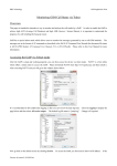
Note: If the GoIP Gateway is placed in local LAN and accessed by Softswitch
from another public IP, the functionality of Media Relay MUST be enabled to
make sure the voice is working in full duplex mode. The following figure shows
the Media Relay setting of VOS Softswitch.
YX Tech
12/21/2012
39
YX GoIP User Manual
5.2 Access from Mobile Network to IP
GoIP Gateway can be used as the access from mobile network to IP. Any call
made to the mobile card inserted into GoIP Gateway will be routed to IP network
and connected to Softswitch server. The Softswitch server can redirect the caller
to final destination user.
Note: If the GoIP Gateway is placed in local LAN and accessed by Softswitch
from another public IP, the functionality of Media Relay MUST be enabled to
make sure the voice is working in full duplex mode.
YX Tech
12/21/2012
40
YX GoIP User Manual
6 FAQ
This chapter presents
corresponding solutions.
the
most
frequently
encountered
issues
and
6.1 How to designate a port for outbound call
Sometimes the outbound call to mobile network is required to be called through
one or any one of a designated group of GoIP Gateway ports in order to reduce
the cost. Here is an example to show you how to complete the settings for GoIP
Gateway to make outbound call through a designated port.
Note:
1) Field Multiple Port Support must be enabled.
2) Field Phone Number Registration must be enabled.
3) Column SIP Phone Number in SIP Account list must be set. The Phone
Number can be regarded as the SIP port phone number and can be called by
other parties. This is the key point to outbound through a designated port.
4) Based on the example from the figure above, SIP Port 1 to 4 are grouped
with phone number 222, SIP Port 5 to 7 is grouped with phone number 666
and SIP Port 8 is grouped with phone number 888. However, only one port
exists in the third group.
a) The outbound call whose destination is prefixed with 222, such as
22213512345678 will be routed to any of the SIP Port 1 to 4.
b) The outbound call whose destination is prefixed with 666, such as
66613512345678 will be routed to any of the SIP Port 5 to 7.
YX Tech
12/21/2012
41
YX GoIP User Manual
c) The outbound call whose destination is prefixed with 888, such as
88813512345678 will be routed to SIP Port 8.
YX Tech
12/21/2012
42
YX GoIP User Manual
7 Appendix 1
This chapter shows the AT commands in detail.
惠州市粤讯网络科技有限公司
Huizhou YueXun Network Technology Co.,Limited
粵訊國際信息有限公司
YX International Information Co.,Limited
Email:
[email protected]
Tel:
+86-400-777-0752(China)
+86-752-2777557; +86-752-2777558(Huizhou China)
+86-755-33599922(Shenzhen China)
+86-20-82404686 (Guangzhou China)
Website:
www.yx19999.net www.yx19999.com
YX Tech
12/21/2012
43