1
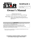
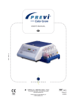
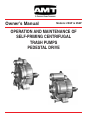
Owner’s Manual
Models: 2S5P & 3S5P
OPERATION AND MAINTENANCE OF
SELF-PRIMING CENTRIFUGAL
TRASH PUMPS
PEDESTAL DRIVE
WARNING!!
DO NOT USE PUMP IN EXPLOSIVE ATMOSPHERE
DO NOT PUMP VOLATILE OR FLAMMABLE LIQUIDS
Installation & Operating Instructions
Self-Priming Centrifugal Pump
BASIC PUMP INSTRUCTIONS
INSPECTION: The pump assembly was tested and
inspected before shipment. Before installation, inspect
the pump for damage which may have occurred during
shipment. Check the following: 1. Inspect for cracks,
damaged threads, and other obvious damage. 2.
Check and tighten loose bolts, nuts and other
attaching hardware. 3. Carefully read all warning and
cautions in the manual and on tags and labels on the
pump. 4. Note the direction of rotation indicated on the
pump. Check that the pump shaft rotates
counterclockwise facing the pump suction. CAUTION:
Only operate this pump in the direction indicated by
the arrow on the bearing pedestal. Otherwise, the
impeller could become loosened from the shaft and
seriously damage the pump.
PLACING PUMP: Locate the pump as close to the
liquid to be pumped as practical, but never higher than
25 feet. Level mounting is essential for proper
operation. The pump may have to be supported to
provide level operation and to eliminate vibration.
SUCTION AND DISCHARGE PIPING: Either pipe or
hose may be used for suction and discharge lines. If
hose is used in suction lines, it must be the rigid-wall,
reinforced type to prevent collapse under suction.
Using pipe couplings in the suction lines is not
recommended. Keep suction and discharge lines as
straight as possible and make minimum use of elbows
and fittings to minimize friction losses.
the pump. If hoses are used, they should have
adequate support to secure them when filled with
liquid.
SUCTION LINES: The suction line must be as short
and direct as possible and the line must always slope
upward to the pump from the source of the liquid. The
suction line should not exceed 30 feet in length.
Suction lines should be the same size as the pump
inlet. Use pipe sealant on the threads of the fittings.
STRAINERS: A strainer is furnished with the pump,
be certain to use it. It is provided with openings small
enough to prevent big stones, etc. from damaging the
impeller. Keep strainer clean. If possible, suspend it to
keep it from working into sediment.
VALVES: A check valve in the discharge line is
normally recommended, but it is not necessary in low
discharge head applications. If a throttling valve is
desired in the discharge line, use a valve as large as
the largest pipe to minimize friction losses. With high
discharge heads, it is recommended that a throttling
valve and a check valve be installed in the discharge
line to protect the pump from excessive shock
pressure and reverse rotation when it is stopped.
BYPASS LINES: If it is necessary to permit the
escape of air to atmosphere during initial priming or in
the repriming cycle, install a bypass line between the
pump and the discharge check valve. The bypass line
should be sized so that it does not affect pump
discharge capacity.
ALIGNMENT: The alignment of the pump and its
power source is critical for trouble-free mechanical
operation. The driver and pump must be mounted on a
common base so that their shafts are aligned with and
parallel to each other. It is imperative that alignment
be checked after the pump and piping are installed,
and before operation. WARNING: When checking
alignment, disconnect the power source to ensure that
the pump will remain inoperative.
FIGURE 1 illustrates a typical installation. A bypass
line may be required for priming on high discharge
head applications.
CONNECTIONS TO PUMP: Before tightening a
connection pipe, align it exactly with the pump port.
Never pull a pipe line into place by tightening the
flange bolts and/or couplings. Lines near the pump
must be independently supported to avoid strain on
COUPLED DRIVES: When using couplings, the axis
of the power source must be aligned to the axis of the
pump shaft in both the horizontal and vertical planes.
Most couplings require a specific gap or clearance
between the driving and the driven shafts. Refer to the
coupling manufacturer’s service literature. The
coupling is in alignment when the hub ends are the
same distance apart at all points. (See Figure 2)
casing has evaporated. Once the pump casing has
been filled, the pump will prime and reprime as
necessary. To fill the pump, remove the pump casing
fill plug at the top of the casing and add clean liquid
until the pump is filled. Replace the fill plug before
operating the pump.
FIGURE 2 Aligning Couplings
Check parallel adjustment by laying a straightedge
across both coupling rims at the top, bottom, and side.
When the straightedge rests evenly on both halves of
the coupling, the coupling is in horizontal parallel
alignment. If the coupling is misaligned, use a feeler
gauge between the coupling and the straightedge to
measure the amount of misalignment.
V-BELT DRIVES:
recommended.
V-Belt
drives
are
not
WARNING: Do not operate the pump without a guard
over the rotating parts. Exposed rotating parts can
catch clothing, fingers, or tools, causing severe injury
to personnel.
PUMP BEARING PEDESTAL: The shaft bearings
are permanently lubricated by the manufacturer and
sealed. Routine maintenance is not required.
POWER UNIT PREPARATION - ELECTRIC
MOTORS: Make certain the input power to your
electric motor is proper, single phase or three phase,
and is of the proper voltage according to the motor
specification plate. Be sure of the proper motor
rotation.
Pump
impeller
should
rotate
counterclockwise, looking from the suction inlet side.
For single phase motors consult the motor
manufacturer’s instructions for wiring for
counterclockwise rotation. Three phase motor rotation
may be reversed by inter-changing any two of the
three power leads. Make certain that wiring for your
electric motor complies with all existing local codes.
POWER UNIT PREPARATION - GASOLINE ENGINE
DRIVEN PUMPS: For complete operating and
maintenance information consult the engine
manufacturer’s instructions included with the engine.
Before starting, fill crankcase with oil specified by the
engine manufacturer. CAUTION: Always remove
spark plug or spark plug wire before working on unit to
prevent accidental starting.
PUMP OPERATION: This pump is self-priming, but
the pump should never be operated unless there is
liquid in the casing. CAUTION: The pump will not
prime when dry. Operation of a dry pump will destroy
the seal assembly. Add liquid to the pump casing
when: 1. The pump is being put into service for the
first time. 2. The pump has not been used for a
considerable length of time. 3. The liquid in the pump
STARTING: Consult the operations manual furnished
with the power source. WARNING: Do not use pump
in explosive atmosphere. Do not pump volatile or
flammable liquids.
OPERATION: Open all valves in the discharge line
and start the power source. Priming is indicated by a
quieter operation. The pump may not prime
immediately because the suction line must first fill with
liquid. If the pump fails to prime within five minutes,
stop it and check the suction line for leaks. After the
pump has been primed, partially close the discharge
line throttling valve in order to fill the line slowly and
guard against excessive shock pressure which could
damage the pump, pipe, gaskets, sprinkler heads, and
any other fixtures connected to the line. When the
discharge line is completely filled, adjust the throttling
valve to the required flow rate. No leakage should be
visible at pump mating surfaces, or at pump
connections or fittings.
LIQUID TEMPERATURE AND OVERHEATING: The
maximum liquid temperature for this pump is 160
degrees Fahrenheit. Do not apply it at a higher
operating temperature. Overheating can occur if
operated with the valves in the suction and discharge
lines closed. Operating against closed valves could
bring the liquid to a boil, build pressure, and cause the
pump to rupture or explode. If overheating occurs,
stop the pump and allow it to cool before servicing it.
Refill the pump casing with cool liquid.
STOPPING: Never halt the flow of liquid suddenly. If
the liquid being pumped is stopped abruptly,
damaging shock waves can be transmitted to the
pump and piping system. Close all connecting valves
slowly. After stopping the pump, lock out the power
supply to ensure that the pump will remain inoperative.
Flush out the pump if the liquid being pumped will
leave a sticky residue or will harden.
DRAINING: During freezing weather, be sure to drain
the pump when it is not in use. Unscrew the drain plug
and run engine or motor about half a minute without
pumping.
STORAGE: When the pump is out of service for long
periods, drain it and store in a dry, well-ventilated
room. Pull the engine hard against compression so
that the valves will be sealed. (Never run pump dry for
more than half a minute or the shaft seal may be
damaged.)
TROUBLES AND THEIR CURES
If difficulties are experienced, in the majority of cases
they can be traced to well-known causes. We suggest
you check these points first to save needless expense.
If the pump fails to prime: (A) Make sure the pump
casing is full of cool liquid. (B) If difficulty continues,
remove suction hose, start engine and hold a flat piece
of rubber sheet, or other suitable material against the
suction inlet. If the pump develops a strong pull
against the material, the trouble is not in the pump. If
there is no pull, the shaft seal may need replacing. (C)
Examine suction hose or pipe connections. Air leaks in
the suction line and connection to the pump are the
most frequent causes of priming trouble. Use new
gaskets in hose coupling. New couplings sometimes
require 2 gaskets. Lining of hose may also become
loose and clog the hose. (D) Keep pump as close to
the level of the liquid being pumped. It will give best
performance on suction lifts less than 15 feet. (E) Be
sure strainer is not clogged. (F) There are no parts or
valves to become clogged or out of adjustment. The
only requirement is that the pump case is full of liquid.
(G) Keep your pump unit clean and properly serviced.
Care in this respect will repay in many years of
trouble-free operation.
Parts List
MODEL
REF. #
1
2
3
4
5
8
9
13 STD
13 ALT
13 C.I. ALT
15 STD
15 ALT
17 STD
17 ALT
18 STD
18 ALT
18 C.I. ALT
19
20 STD
20 ALT
28 STD
28 ALT
32
33
34
35
36
40
41
42
43
46
NOT SHOWN
NOT SHOWN
NOT SHOWN
PART NAME
PEDESTAL (COMPLETE ASSY)
IMPELLER
SEALING WASHER (SET OF FOUR)
BOLT, 5/16-24 X 1.38 SST
SLINGER
SHAFT SEAL, SIC-VITON®
HANDLE
BRACKET-ROTO FINISH
BRACKET-WHITE EPOXY
BRACKET-CAST IRON BLK
BODY O-RING, EPDM
BODY O-RING, VITON®
PLUG & O-RING EPDM
PLUG & O-RING VITON®
BODY-ROTO FINISH
BODY-WHITE EPOXY
BODY-CAST IRON BLK
VOLUTE
CHECK VALVE EPDM
CHECK VALVE VITON®
O-RING EPDM
O-RING VITON®
ROLL PIN LONG
ROLL PIN SST
O-RING RETAINING (SET OF 6)
SHIM, IMPELLER (SET OF 4)
SPACER, IMPELLER
PEDESTAL HOUSING
BEARING
SHAFT
SNAP RING
SPACER (USE OPTIONAL)
TRASH STRAINER
SEAL & O-RING KIT EPDM STD
SEAL & O-RING KIT VITON® ALT
QTY
1
1
1
4
1
1
6
1
1
1
1
1
2
2
1
1
1
1
1
1
1
1
1
5
1
1
1
1
2
1
1
3
1
1
1
Viton is a registered trademark of DuPont Dow Elastomers.
2S5P
3S5P
2S5P
3S5P
5/8" SHAFT
35-320-A
2-127-A
16-233-1
19-216
12-117-B
3-258-A
32-134
5-128-1B
5-128-2B
5-372-1B
12-133
12-133-A
11-116-1
11-116-1A
6-129-1A
6-129-2A
6-370-1A
1-139
7-136-1
7-136-1A
12-160
12-160-A
21-316
21-298
12-299-1
22-255-1A
23-301-A
35-320
47-324
34-321
37-325
28-258
44-278
50-006
50-006-A
5/8" SHAFT
35- 320-A
2- 313-A
16- 233-1
19- 216
12- 117-B
3- 258-A
32- 196
5- 128-1B
5- 128-2B
5-372-1B
12- 133
12- 133-A
11- 116-1
11- 116-1A
6- 131-1A
6- 131-2A
6- 371-1A
1- 312
7- 137-1
7- 137-1A
12- 160
12- 160-A
21- 316
21- 298
12- 299-1
22- 255-1A
23- 301-A
35- 320
47- 324
34- 321
37- 325
28- 258
44- 314
50- 007
50- 007-A
3/4" SHAFT
35- 320-B
2- 127
16- 233-1
19- 216
12- 117-B
3- 258-A
32- 134
5- 128-1B
5- 128-2B
5- 372-1B
12- 133
12- 133-A
11- 116-1
11- 116-1A
6- 129-1A
6- 129-2A
6- 370-1A
1- 139
7- 136-1
7- 136-1A
12- 160
12- 160-A
21- 316
21- 298
12- 299-1
22- 255-1
23- 301
35- 320
47- 324
34- 322
37- 325
28- 258
44- 278
50- 006
50- 006-A
3/4" SHAFT
35-320-B
2-313
16-233-1
19-216
12-117-B
3-258-A
32-196
5-128-1B
5-128-2B
5-372-1B
12-133
12-133-A
11-116-1
11-116-1A
6-131-1A
6-131-2A
6-371-1A
1-312
7-137-1
7-137-1A
12-160
12-160-A
21-316
21-298
12-299-1
22-255-1
23-301
35-320
47-324
34-322
37-325
28-258
44-314
50-007
50-007-A
Seal and O-Ring Kit Contains:
Body-O-Ring, Sealing Washer Set, Volute-O-Ring, Plugs,
Shaft Seal, Spacer, Shim Set, Check Valve, Instruction Sheet,
and Seal Installation Tool.
How To Order Repair Parts For Your
Self-Priming Centrifugal Pump
All parts shown on the parts list and on the exploded
view drawing may be ordered through the nearest
distributor.
When Ordering Repair Parts,
Always Give The Following Information:
1. Identify pump model number.
2. Part name and number. (Not illustration number)
3. Quantity required.
4. Material specification if other than standard.
NOTES
WARNING!!
DO NOT USE PUMP IN EXPLOSIVE ATMOSPHERE
DO NOT PUMP VOLATILE OR FLAMMABLE LIQUIDS
Installation & Operating Instructions
Self-Priming Centrifugal Pump
REPAIR AND MAINTENANCE
INSTRUCTIONS:
To disassemble pump, follow these steps:
1. Remove handles (9).
2. Remove body (18).
3. Remove the volute (19).
4. Follow these instructions for removing the impeller
(2): Remove the impeller by rotating the impeller
counter-clockwise. It may be necessary to strike
the end of one of the impeller vanes with a wood
block and hammer to start the counter-clockwise
rotation.
5. If the mechanical shaft seal (8) needs replacing:
a. With a screwdriver, pry the white seal ring and
its rubber boot out of the back of the impeller.
b. Remove the pump bracket (rear housing) (13)
by removing the four bolts (4).
c.
To remove the seal assembly (8) from the rear
housing, drive it out from behind.
6. To replace the seal component in the rear
housing, coat the bore in the housing where the
seal goes with gasket material (Permatex or
equivalent) and press the seal component into the
housing by using an arbor press or drill press.
Use a short piece of pipe that fits on the small
flange of the seal case so that you are not
pressing on the delicate, finely finished, carbon
seal ring. Do not damage the seal face.
7. To replace the seal component in the impeller
hub, lubricate the outside of the rubber boot with
vegetable oil or soap and press the white ring and
rubber boot into the hub using your two thumbs.
Be certain that the seal ring is all the way down
and even with the back of the impeller so that the
ring does not wobble when the impeller rotates on
the shaft. Do not damage the surface of the white
ring.
8. Re-assemble the pump in the reverse manner
from the disassembly. Use thread sealant on four
(4) bolts that bolt bracket to pedastal.
To disassemble the bearing pedestal, follow these
steps:
1. Remove the pump - step 1 through 5b above.
2. Remove snap ring (43) and tap shaft out with
rubber mallet or use wood block to protect shaft at
impeller end.
3. Remove bearings with bearing puller or by tapping
shaft off bearings. Use rubber mallet or wood
block to protect shaft.
4. Clean bearing bores in pedestal and shaft
surfaces and apply Loctite 609 or 620 or
comparable product to shaft bearing surfaces and
install bearings.
5. Apply the loctite or comparable product to bearing
surfaces in pedestal and install shaft and bearings
in pedestal.
6. Replace snap ring and re-assemble pump in
reverse manner from disassembly.
9/01 46-053
Specifications Information and Repair Parts Manual
NOTES:
Specifications Information and Repair Parts Manual
NOTES:
www.amtpump.com