1
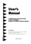
Trident
Three Bus Power Supply
®
Augustica
T e c h n o l o g i e s
www.augustica.com
®
Augustica
®
Technologies
DANGER
This power supply kit uses high-voltage and therefore may produce a lethal shock.
Only persons who are competent at electronics assembly and understand the
dangers of high voltages may attempt to assemble this kit! Safe assembly and
operation of this kit is the users responsibility. The kit and this user manual are
provided 'as is'. Augustica Technologies Inc does not accept responsibility for any
damage, injury or death as a result of assembling this kit or using the information
herein. The assembled kit must be properly enclosed to prevent contact with high
voltages and kept out of reach of children. Keep this kit away from water and other
damp environs. As with any self-assembled electronics project improper assembly
could cause damage to the kit, overloading of a circuit or an electrical fire. If you
don't feel comfortable in assembling the kit or using the power supply, please
contact us to return it for a full refund.
Ideally, a variac should be used to slowly power up the kit, as it is better to have a
misoriented electrolytic capacitor or a mislocated resistor blow at low voltages,
rather than at high voltages. Once the power supply is powered up, be cautious at
all times. In fact, even when the power supply is disconnected or shut down, assume
that capacitors of the power supply will have their high voltage charges retained
and, therefore, still will be able to provide a lethal shock.
Wear safety eye goggles, which is not as bizarre as it may sound - a bursting power
supply capacitor may spray hot caustic chemicals in your face. Make a habit of
using only one hand, with the other hand behind your back, while attaching probes
or handling high voltage gear, as a current flow across your chest can result in
death. In addition, wear rubber-soled shoes and work in dry environment.
Remember, safety first, second, and last.
If you are not an experienced electrical practitioner, before attaching the
transformer windings to the printed circuit board (PCB) of the power supply, have
someone who is well experienced in electronics review your work. Again, if you
don't feel comfortable in assembling the kit or using the power supply, please
contact us to return it for a full refund.
Page 2 of 7
Augustica
®
Technologies
Trident® Power Supply - Theory of Operation
The circuit of the power supply Trident® is shown in Figure 1 (power supply's schematic
also appears on the website www.Augustica.com). The power supply Trident® uses two
transformers (not shown on the schematic). The first transformer is employed to provide
high B-plus voltage of 220 Volt AC and is connected to the terminal block K1. The
second transformer has two secondary windings and is employed to provide low
(filament) voltage of 8 Volt AC to the left and right filament buses of the power supply.
The first secondary winding is connected to the terminal block K3. The second secondary
winding is connected to the terminal block K5.
The high AC voltage produced by the first transformer is rectified by the rectifying
bridge D1-D4 and then is smoothened by capacitors C5, C6, C7, and C8. The capacitors
connected in parallel with the diodes of the rectifying bridge D1-D4 suppress highfrequency noise generated by the diodes of the rectifying bridge D1-D4. The high DC
voltage then is applied to a MOSFET transistor IC1 that serves as a voltage regulator and
AC filter. Resistors R1 and R2 are responsible for a 15 second delay during which the
high B-plus DC voltage reaches its maximum level of 320 Volt. This delay is
significantly increases longevity of tube lifespan in the circuit to which the power supply
Trident® delivers B plus voltage. Finally, additional smoothening of the high B-plus DC
voltage is provided by capacitors C9 and C10. Red LED D7 serves not only as high Bplus DC voltage pilot light, but also, together with resistors R3 and R4, provides a
minimum load and ensures that the high capacitance capacitors C5, C6, C7, C8, C9, and
C10 are discharged once the power supply is switched off, even if no load is connected to
the power supply.
Each of the two filament buses operates in a similar manner. In the left filament bus of
the power supply Trident®, the low AC voltage produced by the second (filament)
transformer is rectified by the rectifying bridge D8–D11 and then is smoothed by
capacitors C15, C16, C17, and C18. The capacitors connected in parallel with the diodes
of the rectifying bridge D8-D11 suppress high-frequency noise generated by the diodes of
the rectifying bridge. High stability filament voltage of 6.3 Volt is produced in a simple
manner using a low voltage drop regulator IC2 LD1084V. Green LED D14 serves not
only as a pilot light, but also, together with resistor R7, provides a minimum load and
ensures that the high capacitance capacitors C15, C16, C17, C18, C19 and C20 are
discharged once the power supply is switched off, even if no load is connected to the
power supply.
In the right filament bus of the power supply Trident®, the low AC voltage produced by
the second (filament) transformer is rectified by the rectifying bridge D15–D18 and then
is smoothed by capacitors C25, C26, C27, and C28. The capacitors connected in parallel
with the diodes of the rectifying bridge suppress high-frequency noise generated by the
diodes of the rectifying bridge. High stability filament voltage of 6.3 Volt is produced in
a simple manner using a low voltage drop regulator IC3 LD1084V. Green LED D21
Page 3 of 7
Augustica
®
Technologies
serves not only as a pilot light, but also, together with resistor R10, provides a minimum
load and ensures that the high capacitance capacitors C25, C26, C27, C28, C29 and C30
are discharged once the power supply is switched off, even if no load is connected to the
power supply.
ASSEMBLY
Cleanliness is essential. Before soldering, be sure to clean both sides the PCB with 70%
to 90% isopropyl alcohol. Do not use dull looking solder. Solder should shine. If it does
not shine, first clean away the outer oxidation with some steel wool or a copper-scouring
pad. If the resistor leads look in the least gray, clean away the oxidation with either steel
wool or a wire sniper’s sharp edges. Admittedly, with new resistors and a fresh PCB,
such metal dulling is rare, but if the parts have sat in your closet for a year or two, then
expect a good amount of oxidation to have developed.
Be consistent in orienting the resistors, capacitors and diodes. Keep nominal information
on a resistor's, capacitor's, or diode's body flowing from the left side to the right side as
you face the resistor, the capacitor, or the diode straight on. This will pay dividends later,
if you need to locate and de-solder a resistor, a capacitor, or a diode placed in a wrong
location. Because the board is double sided, with traces and pads on each side, it is easier
to solder the resistors from their topside. As the PCB is overbuilt, it is difficult to remove
an incorrectly placed part. Be sure to confirm all the electrolytic capacitor orientations, as
a reversed polarized capacitor can easily vent (or even explode) when presented with
high-voltage. Confirm trice, solder once.
Start with assembly of the high B-plus DC voltage bus of the power supply Trident® and
first attach the MOSFET transistor IC1 to its heatsink. This transistor is extremely
sensitive to electric static, therefore, you must use ESD safe soldering station and you
also must ware an ESD bracelet. Once you attached the MOSFET transistor to its
heatsink, you can insert heatsink leads and the MOSFET transistor leads into the PCB.
Solder the leads of the MOSFET transistor to the PCB. At this point do not solder the
heatsink's leads to the PCB - you will do it later.
Second, solder the rectifying bridge D1-D4 and capacitors C1, C2, C3, and C4. Pay
attention to the polarity of the rectifying bridge D1-D4. Solder terminal block K1.
Connect a transformer or variac to the terminal block K1 and slowly bring voltage to 220
Volt AC. Measure the high B-plus DC voltage produced by the rectifying bridge D1-D4.
If you applied 220 Volt AC to the rectifying bridge, after rectification you should obtain
about 320 Volt DC without any load.
Third, solder diodes D5 and D6 and then solder resistors R1 and R2 followed by
capacitors C5, C6, C7, C8, C9 and C10. Now solder red LED D7 and resistors R3 and R4
followed by terminal block K2. Connect a transformer of variac to the terminal block K1
again and slowly bring voltage to 220 Volt AC. Measure the high B-plus DC voltage
Page 4 of 7
Augustica
®
Technologies
produced by the high voltage bus of the power supply (at the terminal block K2) as a
whole. If you applied 220 Volt AC to the terminal block K1, the power supply should
deliver about 320 Volt DC measured at terminal block K2 without any load. Measure AC
component that is present in the DC voltage after it is regulated and filtered by the
MOSFET transistor IC1. The AC component of the high B-plus DC voltage should
fluctuate between 2 millivolts and 20 millivolts AC. If your measurements show
substantially higher values of the AC component present in the high B-plus DC voltage,
your MOSFET transistor IC1 is probably burned out and it has to be replaced. Otherwise,
the MOSFET transistor IC1 is regulating and filtering the high B-plus DC voltage
properly and now you can solder to the PCB the heatsink on which the MOSFET
transistor is situated.
Fourth, assemble the left filament (low DC voltage) bus of the power supply Trident® and
start with attaching IC2 LD1084V low drop voltage regulator to its heatsink. Once you
attached the IC2 LD1084V to its heatsink, you can insert heatsink leads and LD1084V
leads into the PCB. Solder the regulator's leads to the PCB. At this point do not solder the
heatsink's leads to the PCB - you will do it later.
Fifth, solder the rectifying bridge D8-D11 and capacitors C11, C12, C13, and C14. Pay
attention to the polarity of the rectifying bridge D8-D11. Solder terminal block K3.
Connect a transformer of variac to the terminal block K3 and slowly bring AC voltage to
12 Volt AC. Measure the DC voltage produced by the rectifying bridge D8-D11. If you
applied 12 Volt AC to the rectifying bridge, you should obtain about 17 Volt DC after
rectification.
Sixth, solder diodes D12 and D13 and then solder resistors R5 and R6 followed by
capacitors C15, C16, C17, C18, C19 and C20. Now solder green LED D14 and resistor
R7 followed by terminal block K4. Connect a transformer or variac to the terminal block
K3 again and measure the voltage produced by the left filament (low DC voltage) bus of
the power supply as a whole at the terminal block K4. If you applied 12 Volt AC to the
terminal block K3, the power supply should deliver about 17 Volt DC measured at the
terminal block K4 without any load. Measure AC component that is present in the
filament DC voltage after it is regulated and filtered by the IC2 LD1084V. The AC
component of the filament DC voltage should be about 0.6 millivolts AC. If your
measurements show substantially higher value of the AC component present in the DC
voltage, your IC2 LD1084 is probably burned out and it has to be replaced. Otherwise,
the LD1084V is regulating and filtering the filament DC voltage properly and now you
can solder to the PCB the heatsink on which the LD1084V is situated.
Seventh, assemble the right filament (low DC voltage) bus of the power supply Trident®
and start with attaching IC3 LD1084V low drop voltage regulator to its heatsink. Once
you attached the IC3 LD1084V to its heatsink, you can insert heatsink leads and
LD1084V leads into the PCB. Solder the regulator's leads to the PCB. At this point do
not solder the heatsink's leads to the PCB - you will do it later.
Page 5 of 7
Augustica
®
Technologies
Eighth, solder the rectifying bridge D15-D18 and capacitors C21, C22, C23, and C24.
Pay attention to the polarity of the rectifying bridge D15-D18. Solder terminal block K5.
Connect a transformer of variac to the terminal block K5 and slowly bring AC voltage to
12 Volt AC. Measure the DC voltage produced by the rectifying bridge D15-D18. If you
applied 12 Volt AC to the rectifying bridge D15-D18, you should obtain about 17 Volt
DC after rectification.
Ninth, solder diodes D19 and D20 and then solder resistors R8 and R9 followed by
capacitors C25, C26, C27, C28, C29 and C30. Now solder green LED D21 and resistor
R10 followed by terminal block K6. Connect a transformer or variac to the terminal
block K5 again and measure the voltage produced by the right filament (low DC voltage)
bus of the power supply as a whole. If you applied 12 Volt AC to the terminal block K5,
the power supply should deliver about 17 Volt DC measured at the terminal block K6
without any load. Measure AC component that is present in the filament DC voltage after
it is regulated and filtered by the IC3 LD1084V. The AC component of the filament DC
voltage should be about 0.6 millivolts AC. If your measurements show substantially
higher value of the AC component present in the DC voltage, your IC3 LD1084 is
probably burned out and it has to be replaced. Otherwise, the LD1084V is stabilizing and
filtering the filament DC voltage properly and now you can solder to the PCB the
heatsink on which the IC3 LD1084V is situated.
TESTING
First, attach only one (left bus) of the two windings of the low voltage filament power
supply’s transformer to the terminal block K3, leaving the second (right bus) winding of
low voltage filament power supply's transformer and the high voltage transformer
windings unattached and electrical tape shrouded.
Second, if you are using a variac, slowly bring up the low AC voltage to 12 Volt AC,
while looking for smoke or part discoloration or bulging.
Third, measure the filament voltage regulator IC2 LM1084V output voltage across
terminal block K4 without and with a load. If the filament voltage regulator IC2
LD1084V fails to regulate, try either lowering the filament voltage a tad, or increasing it
a tad, for example try 16 Volt instead of 17 Volt, as the 1 Volt difference might be
enough to bring the regulator back into regulation. Power down the left filament bus of
the power supply by disconnecting low voltage filament transformer or variac.
Fourth, attach second winding (right bus) of low voltage filament power supply’s
transformer to the terminal block K5, leaving the high voltage transformer windings
unattached and electrical tape shrouded.
Fifth, if you are using a variac, slowly bring up the low AC voltage to 12 Volt AC, while
looking for smoke or part discoloration or bulging.
Page 6 of 7
Augustica
®
Technologies
Sixth, measure the filament voltage regulator IC3 LM1084V output voltage across
terminal block K6 without and with a load. If the filament voltage regulator IC3
LD1084V fails to regulate, try either lowering the filament voltage a tad, or increasing it
a tad, for example try 16 Volt instead of 17 Volt, as the 1 Volt difference might be
enough to bring the regulator back into regulation. Power down the right filament bus of
the power supply by disconnecting low voltage filament transformer or variac.
Seventh, attach the high B-plus voltage transformer or variac windings to the terminal
block K1 and slowly bring up the high AC voltage to 220 Volt AC, while looking for
smoke or part discoloration or bulging.
Eighth, measure the B-plus voltage across the terminal block K2. If you applied 220 Volt
AC to the terminal block K1, the power supply should deliver about 320 Volt DC
measured at the terminal block K2 without any load. If a load is attached to the terminal
block K2, the power supply should deliver 270 - 280 Volt DC depending on resistance of
the load.
Only after you are sure that both filament and B-plus buses are working properly should
you attach the power supply to a headphone.
LET US KNOW WHAT YOU THINK
If you would like to see some new audio PCB or kit or recommend a change to an
existing product, drop us a line by e-mail on the website www.Augustica.com (begin the
subject line with “Trident” or the spam filters are sure to eat your message).
Page 7 of 7