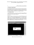
1
HT80C51 User Manual
Handshake Solutions
HT80C51 User Manual
Document Information
Handshake Solutions
Document Information
Document Title
HT80C51 User Manual
Date of Creation
27/06/2005
Date of last change
27/06/2005
File name
HT80C51-UserManual.doc
Status
Release
Version Number
1.7
Client / Target Audience
System architects,and software developers using the HT80C51
Summary
This document describes and illustrates the general architecture, the
standard peripherals and the instruction set for the HT80C51.
Contact
Handshake Solutions
High Tech Campus
Prof. Holstlaan 4
Mailbox WAM01
5656 AA Eindhoven
The Netherlands
phone: +31-40-27 46114
fax:
+31-40-27 46526
[email protected]
www.handshakesolutions.com
© 2005 Koninklijke Philips Electronics N.V.
All rights reserved. Reproduction in whole or in part in any way, shape or form, is prohibited without
the written consent of the copyright owner. All information in this document is subject to change without notice.
Page 2 of 132
© Philips Electronics N.V. 2005
HT80C51 User Manual
Table of Contents
Handshake Solutions
Table of Contents
1.
Introduction to HT80C51 ............................................................................................................... 5
1.1.
Compatibility ..................................................................................................................... 5
1.2.
2.
Memory Organization .................................................................................................................... 9
2.1.
Memory Map ...................................................................................................................... 9
2.2.
Accessing Program Memory ......................................................................................... 10
2.3.
Accessing External Data Memory ................................................................................. 10
2.4.
Internal Data Memory: Direct and Indirect Address Area........................................... 11
2.5.
Special Function Registers............................................................................................ 13
2.6.
3.
4.
2.5.1.
Accumulator ACC .............................................................................................. 14
2.5.2.
Register B .......................................................................................................... 14
2.5.3.
Program Status Word PSW............................................................................... 14
2.5.4.
Stack Pointer SP ............................................................................................... 14
2.5.5.
Data Pointer DPTR DPH DPL ........................................................................... 15
2.5.6.
Power Saving Modes PCON ............................................................................. 15
2.5.7.
External RAM Page XRAMP (option HT80C51_CPU_XRAMP)....................... 17
MOVC protection (option HT80C51_CPU_MOVCP)..................................................... 17
Reset ............................................................................................................................................. 18
Clocks ........................................................................................................................................... 19
4.1.
CPU Cock......................................................................................................................... 19
4.2.
5.
Modules.............................................................................................................................. 6
4.1.1.
Clockless (Aynchronous) Cnfiguration .............................................................. 19
4.1.2.
Clock synchronization (Option HT80C51_CPU_SYNC) ................................... 19
Peripheral clocks ............................................................................................................ 19
Peripheral Modules...................................................................................................................... 20
5.1.
Interrupt Controller ......................................................................................................... 20
5.2.
5.3.
5.1.1.
Options .............................................................................................................. 20
5.1.2.
Special function registers (IEN0 IEN1 IP0 IP1) ................................................. 20
5.1.3.
Operation ........................................................................................................... 22
5.1.4.
Setting up the Interrupt Controller ..................................................................... 25
Timers 0 and 1 ................................................................................................................. 26
5.2.1.
Options .............................................................................................................. 26
5.2.2.
Special function registers (TMOD TCON TL0 TL1 TH0 TH1)........................... 26
5.2.3.
Interrupts............................................................................................................ 28
5.2.4.
Operation ........................................................................................................... 29
5.2.5.
Setting up the Timers ........................................................................................ 31
Standard Serial Interface (SIO0) .................................................................................... 33
5.3.1.
Options .............................................................................................................. 33
5.3.2.
Special function registers (SCON SBUF SMOD) .............................................. 33
© Philips Electronics N.V. 2005
Page 3 of 132
Handshake Solutions
HT80C51 User Manual
Table of Contents
5.3.3.
Interrupts............................................................................................................ 34
5.3.4.
Operation ........................................................................................................... 34
5.3.5.
Setting up the serial port.................................................................................... 40
5.4.
5.5.
5.6.
5.7.
5.8.
6.
General Purpose IOs ...................................................................................................... 42
5.4.1.
Options .............................................................................................................. 42
5.4.2.
Special function registers (POUTx PINx) .......................................................... 42
5.4.3.
Interrupts............................................................................................................ 43
5.4.4.
Operation ........................................................................................................... 43
2
I C Interface (SIO1).......................................................................................................... 44
5.5.1.
Options .............................................................................................................. 44
5.5.2.
Special function registers (S1CON S1ADR S1DAT S1STA ) ........................... 44
5.5.3.
Interrupts............................................................................................................ 46
5.5.4.
Operation ........................................................................................................... 46
5.5.5.
Slave-only version ............................................................................................. 73
5.5.6.
Application notes ............................................................................................... 73
Serial Peripheral Interface (SPI) .................................................................................... 74
5.6.1.
Options .............................................................................................................. 74
5.6.2.
Special function registers (SPCR SPSR SPDR) ............................................... 74
5.6.3.
Interrupts............................................................................................................ 76
5.6.4.
Operation ........................................................................................................... 76
Watchdog Timer (under development) ......................................................................... 80
5.7.1.
Options .............................................................................................................. 80
5.7.2.
Special function registers (T3)........................................................................... 80
5.7.3.
Interrupts............................................................................................................ 80
5.7.4.
Operation ........................................................................................................... 80
Triple-DES Converter...................................................................................................... 82
5.8.1.
Options .............................................................................................................. 82
5.8.2.
Special function registers (DCON DKEY DTXT) ............................................... 82
5.8.3.
Interrupts............................................................................................................ 83
5.8.4.
Operation ........................................................................................................... 83
5.8.5.
Software view .................................................................................................... 84
80C51 Family Instruction Set...................................................................................................... 87
6.1.
80C51 Instruction Set Summary.................................................................................... 87
6.2.
Instruction definitions .................................................................................................... 91
Appendix ............................................................................................................................................ 130
A1:
List of Tables ................................................................................................................. 130
A2:
List of Figures ............................................................................................................... 131
A3:
Document History ......................................................................................................... 132
Page 4 of 132
© Philips Electronics N.V. 2005
HT80C51 User Manual
Introduction to HT80C51 – Compatibility
1.
Handshake Solutions
Introduction to HT80C51
The Handshake Technology 80C51 (referred to as HT80C51) is an improved version of the ultra lowpower 80C51 (known as ulp80C51). This ulp80C51 has been used in several products such as
pagers, game controllers, telephony controllers, and Mifare ProX and SmartMX smart card controllers.
Millions of these ICs have been shipped.
The HT80C51 implementation offers several unique features, which are detailed below.
•
The HT80C51 is extremely low power (the CPU consumes only 0.1 nano joules per instruction).
•
The HT80C51 has very low electromagnetic emission (EME).
•
The HT80C51 has low supply-current peaks (at least a factor five lower than traditional, clocked
implementations), thus facilitating integration with analog and RF circuitry.
•
The HT80C51 CPU consumes zero stand-by power while in sleep mode, yet is immediately
available for full-speed full-functional operation.
•
The HT80C51 has an asynchronous and optionally a synchronous mode of operation. When
both are present, the actual mode can be dynamically selected on an instruction-per-instruction
base. This is controlled via a dedicated input.
•
In asynchronous mode of operation, the CPU runs at its natural speed, and a slow core clock
does not slow it down.
•
In synchronous mode, the CPU synchronizes with a clock on a machine cycle basis after each
instruction in such a way that the number of clock cycles for that instruction is the same as the
number of machine cycles for a synchronous implementation.
•
The HT80C51 core is configurable, and has a range of configuration options, offering selective
instantiations of 80C51 peripherals and customization of memory interfaces.
•
The HT80C51 peripherals consume zero power when not actively used.
•
Optional dual datapointer (for more compact code).
•
Optional MOVC protection (only grants program code from lower program memory permission
to read lower program memory).
1.1.
Compatibility
The HT80C51 implementation is functionally compatible to the instruction set and the peripherals of
the original 80C51.
The HT80C51 and its peripherals have been designed in Haste, which is the high-level programming
language of the Handshake Technology design flow. This design flow is to a large extent technology
independent. Mapping onto various VLSI technologies from different vendors is supported.
For production testing, both functional and scan-test version are supported. The scan-test version is
compatible with standard ATPG tools.
© Philips Electronics N.V. 2005
Page 5 of 132
Handshake Solutions
1.2.
HT80C51 User Manual
Introduction to HT80C51 – Modules
Modules
Following modules are currently available for a HT80C51 microcontroller system
•
•
HT80C51 CPU with optional
-
Prefetch unit to increase performance
-
Dual datapointer
-
MOVC protection
-
Synchronization to external clock
Interrupt controller
-
With configurable number of interrupt lines (1 to 15)
•
Timer 0 and timer1
•
UART
•
SPI
•
I2C
-
Master/slave or
-
Slave only
•
Watchdog Timer
•
DES
•
Bridge to synchronous SFR bus
-
Supports legacy synchronous peripheral units
Other peripherals are being developed or can be implemented on demand.
Page 6 of 132
© Philips Electronics N.V. 2005
HT80C51 User Manual
Introduction to HT80C51 – Modules
Handshake Solutions
external data
memory
RAM
code memory
code address
internal
data
address
external data
address
B
XRAMP
stack
pointer
ACC
tmp2
buffer register
tmp1
HT80C51
ALU
PC
incrementer
PC
PSW
PCON
DPTR
control
instruction
register
DPTR1
peripheral
special
function
registers
peripheral logic
external logic
[Figure 1]
© Philips Electronics N.V. 2005
HT80C51 Architecture (CPU centered)
Page 7 of 132
HT80C51 User Manual
Introduction to HT80C51 – Modules
Handshake Solutions
external
HT80C51
int_req_i[ ]
interrupt
controller
int4,5,6
up to
64Kbytes
int_ack_o[ ]
int0..3
program
memory
timer 0 / 1
t1_overflow
up to
64Kbytes
external
data
memory
(optional)
UART
I 2C
80C51
CPU
SPI
up to
256bytes
internal
data
memory
Watchdog
handshake
peripherals
synchronous
peripherals
DES
gpio_pinX[ ]
synchronous
SFR bus bridge
GPIO
gpio_poutX[ ]
HT-SFR bus
[Figure 2]
Page 8 of 132
HT80C51 Achitecture
© Philips Electronics N.V. 2005
HT80C51 User Manual
Memory Organization – Memory Map
2.
Handshake Solutions
Memory Organization
The 80C51 architecture comprises several different and separated address areas. The following chapter describes the map of these memory areas, which are described in more detail thereafter.
2.1.
Memory Map
The 80C51 has separate address spaces for program memory, external and internal data memory.
[Figure 3] shows a map of the 80C51 memory areas.
program memory
(CODE)
external data
memory
(XDATA)
up to
64 Kbytes
up to
64 Kbytes
internal data
memory
(IDATA, DATA)
FFFH
up to
256 bytes
000H
FFH
00H
[Figure 3]
HT80C51 Memory Map
The Program memory (CODE) can be up to 64Kbytes. It can be accessed by instruction fetches and
by the MOVC instruction.
The 80C51 can address up to 64k bytes of external data memory (XDATA). Historically this area was
located outside the chip (hence the name external), which is usually not the case for embedded systems. The MOVX instruction is used to access the external data memory.
The 80C51 can address up to 256 bytes of on-chip RAM, plus a number of Special Function Registers
(SFRs).
The lower 128 bytes of RAM can be accessed either by direct addressing (MOV data addr) or by indirect addressing (MOV @Ri). The upper 128 bytes of RAM can be accessed by indirect addressing
only. Using addresses 80H to FFH with direct addressing accesses the special function registers.
[Figure 4] shows the internal data memory organization.
© Philips Electronics N.V. 2005
Page 9 of 132
HT80C51 User Manual
Memory Organization – Accessing Program Memory
Handshake Solutions
internal data memory
FFH
upper area of
RAM
(128 bytes)
special functions
registers (SFRs)
80H
7FH
lower area of
RAM
(128 bytes)
00H
indirect addressing
(IDATA)
[Figure 4]
2.2.
direct addressing
(DATA)
Memory map of Internal Data
Accessing Program Memory
The program memory is readable only and can be accessed by two access methods:
Instruction fetches using the 16bit program counter (PC) as the address or move-code instructions
using the 16bit data pointer (MOVC @DPTR) or again the PC (MOVC @PC) as reference.
2.3.
Accessing External Data Memory
In contrast to the program memory the external data memory is read- and writeable. Accesses to external data memory can be done thru the MOVX-instruction only, which comes in two flavors:
MOVX @DPTR uses the data pointer to form the 16bit address.
MOVX @Ri uses one of the index registers to form the lower 8bits of the address with the upper part
of the address being defined by the SFR XRAMP.
The first variant is usually faster and a more general access method. The second variant (MOVX @Ri)
can be used as a paging access to a rather small area of data.
Page 10 of 132
© Philips Electronics N.V. 2005
HT80C51 User Manual
Memory Organization – Internal Data Memory: Direct and Indirect Address Area
2.4.
Handshake Solutions
Internal Data Memory: Direct and Indirect Address Area
The lower 128 bytes of RAM can be accessed by both direct and indirect addressing and they can be
divided into three segments as listed below and shown in [Figure 5].
7FH
scratch
pad
area
30H
2FH
bit addresses
00 … 7F
bit
addressable
segment
20H
1FH
18H
register bank 3
17H
10H
register bank 2
register
banks
[Figure 5]
0FH
08H
register bank 1
07H
00H
register bank 0
Lower 128 bytes of RAM, direct and indirect addressing
1. Register Banks 0-3:
Locations 00H through 1FH (32 bytes). The device after reset defaults to register bank 0. To use the
other register banks, the user must select them in software. Each register bank contains eight 1-byte
registers 0 through 7. Reset initializes the stack pointer to location 07H, and it is incremented once to
start from location 08H, which is the first register (R0) of the second register bank. Thus, in order to
use more than one register bank, the SP should be initialized to a different location of the RAM where it
is not used for data storage (i.e., the higher part of the RAM).
The register bank is selected by bits RS0 and RS1 in the program status word.
2. Bit Addressable Area:
16 bytes have been assigned for this segment, 20H-2FH. Each one of the 128 bits of this segment
can be directly addressed (0-7FH). The bits can be referred to in two ways, both of which are accept-
© Philips Electronics N.V. 2005
Page 11 of 132
Handshake Solutions
HT80C51 User Manual
Memory Organization – Internal Data Memory: Direct and Indirect Address Area
able by most assemblers. One way is to refer to their address (i.e., 0-7FH). The other way is with reference to bytes 20H to 2FH. Thus, bits 0-7 can also be referred to as bits 20.0-20.7, and bits 8-FH
are the same as 21.0-21.7, and so on. Each of the 16 bytes in this segment can also be addressed
as a byte.
3. Scratch Pad Area:
30H through 7FH are available to the user as data RAM. However, if the stack pointer has been initialized to this area, enough bytes should be left aside to prevent overwriting of stack data.
Page 12 of 132
© Philips Electronics N.V. 2005
HT80C51 User Manual
Memory Organization – Special Function Registers
2.5.
Handshake Solutions
Special Function Registers
The upper address range of the direct addressable data memory is occupied by the special function
registers (SFRs). These registers not only serve as data storage, they also have special function for
the CPU or peripherals they are attached to. A map of this area is shown in [Figure 6].
F8
F0
FF
B
SPCR
SPSR
SPDR
E8
E0
D8
D0
EF
ACC
E7
S1CON S1STA
S1DAT S1ADR
DF
PSW
C8
D7
CF
XRAMP
C0
B8
C7
IP
BF
B0
A8
B7
IE
AF
A0
98
A7
SCON
SBUF
9F
90
88
F7
97
TCON
TMOD
TL0
TL1
SP
DPL
DPH
80
TH0
TH1
8F
PCON
87
↑ SFRs in this column are bit addressable
[Figure 6]
SFR memory map
Note that in the SFR-map not all of the addresses are occupied. Unoccupied addresses are not implemented on the chip. Read accesses to these unimplemented SFR locations will in general return
random data, and write accesses will have no effect. User software should not write 1s to these unimplemented locations, since they may be used in other 80C51 Family derivative products to invoke new
features.
There are two types of special functions registers: registers, which are part of the CPU and often directly used by certain instructions, and SFRs, which are implemented in peripheral blocks. The SFRs
of the CPU are available in all derivatives of this microcontroller and are described in the text below.
Peripheral blocks are optional and so are the SFRs, which are implemented inside these peripherals.
Therefore the peripheral SFRs are described with the peripheral blocks in Chapter 5.
© Philips Electronics N.V. 2005
Page 13 of 132
HT80C51 User Manual
Memory Organization – Special Function Registers
Handshake Solutions
2.5.1.
Accumulator ACC
ACC is the Accumulator register. The mnemonics for Accumulator-Specific instructions, however, refer
to the Accumulator simply as A.
addr = E0H
Accumulator
ACC (A)
bits
7
6
5
4
3
reset value = 00H
2
1
0
ACC
2.5.2.
Register B
The B-register is used during multiply and divide operations. For other instructions it can be treated as
another scratch pad register.
addr = F0H
Register B
B
bits
7
6
5
4
3
reset value = 00H
2
1
0
B
2.5.3.
Program Status Word PSW
The program status word (PSW) register contains program status information as detailed below.
bits
reset value = 00H
7
6
5
4
3
2
1
0
CY
AC
F0
RS1
RS0
OV
-
P
bit
symbol
function
PSW.7
CY
Carry Flag.
PSW.6
AC
Auxiliary Carry Flag.
PSW.5
F0
Flag 0 available to the user for general purpose.
PSW.4
PSW.3
RS1
RS0
Register Bank selector bit 1.
Register Bank selector bit 0.
00
01
10
11
2.5.4.
addr = D0H
Program Status Word
PSW
(RS1, RS0) select the register bank as follows:
Bank 0
(00H .. 07H)
Bank 1
(08H .. 0FH)
Bank 2
(10H .. 17H)
Bank 3
(18H .. 1FH)
PSW.3
RS0
Register Bank selector bit 0 (see note).
PSW.2
OV
Overflow Flag.
PSW.1
-
Usable as a general-purpose flag.
PSW.0
P
Parity flag. Set/cleared by hardware each instruction cycle to indicate an
odd/even number of ‘1’ bits in the accumulator, that means even parity.
Stack Pointer SP
The Stack Pointer (SP) register is 8 bits wide. It is incremented before data is stored during PUSH and
CALL executions. While the stack may reside anywhere in on-chip RAM, the Stack Pointer is initialized
to 07H after a reset. This causes the stack to begin at locations 08H.
Page 14 of 132
© Philips Electronics N.V. 2005
HT80C51 User Manual
Memory Organization – Special Function Registers
SP
Handshake Solutions
addr = 81H
Stack Pointer
bits
7
6
5
4
3
2
reset value = 07H
1
0
SP
2.5.5.
Data Pointer DPTR DPH DPL
The Data Pointer (DPTR) consists of a high byte (DPH) and a low byte (DPL). Its intended function is to
hold a 16-bit address for MOVX and MOVC instructions. It may be manipulated as a 16-bit register or
as two independent 8-bit registers.
DPH
addr = 83H
Data Pointer High byte
bits
7
6
5
4
3
2
reset value = 00H
1
0
DPH
DPL
addr = 82H
Data Pointer Low byte
bits
7
6
5
4
3
2
reset value = 00H
1
0
DPL
2.5.5.1.
Dual data pointer (option HT80C51_CPU_DUALDPTR)
Optional two data pointer registers can be implemented, DPTR0 and DPTR1. Only one data pointer can
be used at a time. This can be selected by bit DPS in SFR PCON (see below).
All instructions using the DPTR, DPL or DPH use either DPTR0 or DPTR1 as selected by SFR bit DPS.
The DPS bit should be saved by software when switching between DPTR0 and DPTR1 within procedures
or interrupt routines.
2.5.6.
Power Saving Modes PCON
The HT80C51 has two power reducing modes, Idle and Power Down. The input through which backup
power is supplied during these operations is VDD.
In the Idle mode (IDL = 1), the oscillator continues to run and the Interrupt, Serial Port, and Timer
blocks continue to be clocked, but the clock signal is gated off to the CPU.
In Power Down (PD = 1), the oscillator is frozen.
Since switching on or off the oscillator is done outside the microcontroller, dedicated output pins indicate idle mode (cpu_idle_o) and power down (cpu_powerdown_o). External circuits needs to observe these signals to switch off the clocks (in power down) or to change the supply voltage.
Setting bits in Special Function Register PCON activate the Idle and Power Down Modes.
© Philips Electronics N.V. 2005
Page 15 of 132
HT80C51 User Manual
Memory Organization – Special Function Registers
Handshake Solutions
addr = 87H
Power Control Register
PCON
Bits
reset value =
0XX00000
7
6
5
4
3
2
1
0
SMOD
-
-
(DPS)
GF1
GF0
PD
IDL
Bit
symbol
PCON.7
SMOD
Function
Double baud rate (see chapter 5.3 “Standard Serial Interface”)
1:
If timer 1 is used to generate the baudrate and the serial interface is
used in modes 1, 2 or 3, then the baudrate is doubled.
0:
The baudrate is not influenced
PCON.6
PCON.5
-
Reserved (write 0, reads 0)
PCON.4
(DPS)
Data pointer select; implemented with dual data pointer option, only,
otherwise reserved bit (write 0, reads 0)
1:
0:
Select DPTR1 for all DPTR accesses (and for DPL and DPH)
select DPTR0 for all DPTR accesses (and for DPL and DPH)
PCON.3
GF1
PCON.2
GF0
General-purpose flag bit.
General-purpose flag bit.
PCON.1
PD
Power-Down bit. Setting this bit activates power-down operation, which
is also indicated at output pin cpu_powerdown_o.
PCON.0
IDL
Idle mode bit. Setting this bit activates idle mode operation, which is
also indicated at output pin cpu_idle_o.
Note: If 1s are written to PD and IDL at the same time, PD takes precedence.
User software should never write 1s to unimplemented bits, since they may be used in other 80C51
Family products.
2.5.6.1.
Idle Mode
An instruction that sets PCON.0 immediately switches into the idle mode, so no further instruction is
executed. The clock signal is gated off from the CPU but not to the Timer and Serial Port functions.
The CPU status is preserved in its entirety; the Stack Pointer, Program Counter, Program Status
Word, Accumulator, and all other registers maintain their data during Idle.
The port pins hold the logical states they had at the time Idle was activated.
There are two ways to terminate the Idle. Activation of any enabled interrupt will cause PCON.0 to be
cleared by hardware, terminating the idle mode. The interrupt will be serviced, and following RETI, the
next instruction to be executed will be the one following the instruction that put the device into Idle.
The flag bits GF0 and GF1 can be used to give an indication if an interrupt occurred during normal operation or during an Idle. For example, an instruction that activates Idle can also set one or both flag
bits. When Idle is terminated by an interrupt, the interrupt service routine can examine the flag bits.
The other way of terminating the idle mode is with a hardware reset, which starts the processor in the
same manner as a power-on reset.
2.5.6.2.
Power-Down Mode
An instruction that sets PCON.1 immediately switches into the Power Down mode. In the Power Down
mode, the CPU clock and all peripheral clocks can be stopped completely to lower the power consumption. This has to be done be external circuits, which observe the output pin cpu_powerdown_o,
that indicates the power down mode. With the clocks frozen, all functions are stopped, the contents of
the on-chip RAM and Special Function Registers are maintained. The port pins output the values held
by their respective SFRs.
The only exit from Power Down is a hardware reset. Reset redefines all the SFRs, but does not
change the on-chip RAM.
Page 16 of 132
© Philips Electronics N.V. 2005
HT80C51 User Manual
Memory Organization – MOVC protection (option HT80C51_CPU_MOVCP)
Handshake Solutions
In the Power Down mode of operation, VDD can be reduced to a level that is still sufficient for logic
and RAM to keep their contents. Care must be taken, however, to ensure that VDD is not reduced
before the Power Down mode is invoked, and that VDD is restored to its normal operating level, before the Power Down mode is terminated. The reset that terminates Power Down also should switch
on the core clock again. The reset should not be activated before VDD is restored to its normal operating level, and must be held active long enough to allow an oscillator to restart and stabilize.
2.5.7.
External RAM Page XRAMP (option HT80C51_CPU_XRAMP)
The MOVX-instruction comes in two flavors: MOVX @DPTR and MOVX @Ri. For the second version
(MOVX @Ri) the contents of one index register Ri specify the lower half of the 16bit address for the
access to the external data memory. The upper half is not specified by the instruction, but the SFR
XRAMP supplies it. In other words, the external data memory is divided into pages of 256bytes, with
XRAMP selecting the page and @Ri addressing within this page.
XRAMP
addr = C9H
External RAM Page
bits
7
6
5
4
3
2
reset value = 00H
1
0
XRAMP
2.6.
MOVC protection (option HT80C51_CPU_MOVCP)
This optional feature protects a memory region in program memory from being read out by a program
outside this region. Thus any MOVC instruction, that is executed outside the protected region and tries
to access the protected region, will return the value 00H instead of the real memory content. The protection is only one-way, so a protected program can read the complete program memory area.
The protected region is defined to start at address 0000H. The upper limit of the protected region is
defined by static inputs ht80c51_movcp_uaddr_i, so the protected code memory region is from
0000H <= addr < ht80c51_movcp_uaddr_i. The value of this upper limit is under control of the
customer, but must not change during execution. Usually it is hard wired to a constant value.
© Philips Electronics N.V. 2005
Page 17 of 132
HT80C51 User Manual
Reset
Handshake Solutions
3.
Reset
The reset input is the Z_R pin. An asynchronous reset is accomplished by holding the Z_R pin low.
The minimum low time is not depending on the clock frequency but it depends on the standard cell
library, placement and routing. However, usually a reset pulse of about 100ns is sufficient.
A reset initializes most of the SFRs. The following table lists the SFR reset values. The internal RAM
is not affected by reset. On power up the RAM content is not defined.
register
PC
0000H
ACC
00H
B
00H
PSW
00H
SP
07H
DPTR
PCON
0000H
0xx0 000
IEN0
00H
IEN1
00H
IP0
IP1
00H
00H
TMOD
00H
TCON
00H
TH0
00H
TL0
00H
TH1
TL1
00H
00H
SCON
SBUF
00H
XX
POUT0
FFH
POUT1
FFH
POUT2
POUT3
FFH
FFH
S1CON
00H
S1STA
F8H
S1DAT
S1ADR
00H
00H
SPCR
0000 0100
SPSR
SPDR
00H
00H
DCON
XX
DKEY
DTXT
XX
XX
Note:
[Table 1]
Page 18 of 132
reset value
“XX” means no initialization on reset.
80C51 SFR Reset Values
© Philips Electronics N.V. 2005
HT80C51 User Manual
Clocks – CPU Cock
4.
Clocks
4.1.
CPU Cock
4.1.1.
Clockless (Aynchronous) Cnfiguration
Handshake Solutions
A handshake circuit does not require a clock to work, it simply adapts its speed to the environment
(other blocks, supply voltage, temperature, etc.). This is a complete asynchronous mode of operation
and our standard configuration of the core.
4.1.2.
Clock synchronization (Option HT80C51_CPU_SYNC)
Some applications or programs require a precisely defined timing behavior of the instruction execution, for instance, when timing or waiting loops are used. For this case an optional synchronization
feature is offered.
With this feature come two additional input pins: cpu_clk_i and cpu_sync_i.
cpu_clk_i delivers the machine clock and thus the speed of the CPU, input cpu_sync_i decides,
whether the CPU should be synchronized to cpu_clk_i or not:
•
In synchronous mode (cpu_sync_i=1), the CPU synchronizes with cpu_clk_i on a machine
cycle basis after each instruction in such a way that the number of clock cycles for that instruction is the same as the number of machine cycles for a synchronous implementation. Since
there are no clock dividers attached, one cpu_clk_i cycle equals to one machine cycle.
•
In asynchronous mode of operation (cpu_sync_i=0), the CPU runs at its natural speed, and a
slow cpu_clk_i does not slow it down.
4.2.
Peripheral clocks
In a traditional (synchronous) 80C51 system, all clocks for peripherals are derived from the clock for
the CPU or from the CPU’s machine cycle, which is usually 1/12 or 1/6 of the CPU clock frequency,
depending on the implementation of the CPU. Hence all timing specifications like timer overflow times
or baud rates were specified in relation to the CPU clock.
In a handshake design no single, global clock source is needed, the clock for the CPU can even be
omitted (which is the standard configuration for the HT80C51). Thus for each peripheral that needs a
clock, e.g. timers, serial interfaces or the synchronous SFR bus, a dedicated clock input is provided.
So the optimum clock frequency can be supplied to each peripheral, completely independent from all
other clock frequencies. Also note, that there is no internal clock divider implemented (divide by 12 or
6). Thus, compared to a synchronous design, the same timings (e.g. baud rates) can be achieved with
a lower input clock frequency resulting in lower power consumption.
The timing specifications of the peripherals are related to their specific input clock frequencies.
© Philips Electronics N.V. 2005
Page 19 of 132
HT80C51 User Manual
Peripheral Modules – Interrupt Controller
Handshake Solutions
5.
Peripheral Modules
For the HT80C51 a number of standard peripherals like timers and serial interfaces exist. They are
compatible to the standard peripherals in synchronous implementations. The peripherals can be ordered along with the CPU and are then part of a combined delivery. The following chapters describe
these peripherals in detail with further options (if available) and their SFRs.
5.1.
Interrupt Controller
This module handles the enabling and priority decoding of interrupt requests as well as entering and
leaving the interrupt routines. The number of interrupt inputs can be configured from 0 up to 15.
5.1.1.
Options
The interrupt controller can be ordered by option HT80C51_INT.
The number of interrupt inputs int_req_i can be selected (ordered) by using option
HT80C51_INT_COUNT.
5.1.2.
Special function registers (IEN0 IEN1 IP0 IP1)
The number of implemented SFRs for the interrupt controller and even the number of bits within these
SFRs depends on the selected number of interrupt inputs. For each interrupt input int_req_i[x]
one interrupt enable bit and one interrupt priority bit exists. All interrupt enable bits are collected in two
SFRs: IEN0 and IEN1. All interrupt priority bits are collected in further two SFRs: IP0 and IP1.
If the number of interrupt inputs is greater than 0, SFRs IEN0 and IP0 exist.
If the number of interrupt inputs is greater than 7, SFRs IEN1 and IP1 exist, too.
addr = A8H
Interrupt enable register 0
IEN0
(IE)
bits
7
6
5
4
3
2
1
0
EA
IEN0.6
ES1
ES0
ET1
EX1
ET0
EX0
bit
symbol
IEN0.7
EA
Function
1:
0:
IEN0.6
IEN0.5
reset value = 00H
General enable/disable control. If EA = 0,
Any individually enabled interrupt will be accepted.
No interrupt is enabled.
Enable interrupt input int_req_i[6].
ES1
Enable I2C interrupt (if available) or interrupt input int_req_i[5].
IEN0.4
ES0
Enable UART interrupt (if available) or interrupt input int_req_i[4].
IEN0.3
ET1
Enable timer 1 overflow interrupt (if available) or interrupt input
int_req_i[3].
IEN0.2
EX1
Enable external interrupt from timer 1 (IE1) (if available) or interrupt
input int_req_i[2].
IEN0.1
ET0
Enable timer 0 overflow interrupt (if available) or interrupt input
int_req_i[1].
IEN0.0
EX0
Enable external interrupt from timer 0 (IE0) (if available) or interrupt
input int_req_i[0].
Bit values: 0 = interrupt disabled; 1 = interrupt enabled.
Page 20 of 132
© Philips Electronics N.V. 2005
HT80C51 User Manual
Peripheral Modules – Interrupt Controller
IEN1
Handshake Solutions
addr = E8H
Interrupt enable register 1
bits
bit
reset value = 00H
7
6
5
4
3
2
1
0
IEN1.7
IEN1.6
IEN1.5
IEN1.4
IEN1.3
IEN1.2
IEN1.1
IEN1.0
symbol
Function
IEN1.7
Enable interrupt input “int_req_i[14]”.
IEN1.6
Enable interrupt input “int_req_i[13]”.
IEN1.5
Enable interrupt input “int_req_i[12]”.
IEN1.4
Enable interrupt input “int_req_i[11]”.
IEN1.3
Enable interrupt input “int_req_i[10]”.
IEN1.2
Enable interrupt input “int_req_i[9]”.
IEN1.1
Enable interrupt input “int_req_i[8]”.
IEN1.0
Enable interrupt input “int_req_i[7]”.
Bit values: 0 = interrupt disabled; 1 = interrupt enabled.
IP0
(IP)
addr = B8H
Interrupt priority register 0
bits
reset value = 00H
7
6
5
4
3
2
1
0
-
IP0.6
PS1
PS0
PT1
PX1
PT0
PX0
bit
symbol
IP0.7
-
IP0.6
Function
reserved.
Priority level for interrupt input int_req_i[6].
IP0.5
ES1
Priority level for I2C interrupt (if available) or interrupt input
int_req_i[5].
IP0.4
ES0
Priority level for UART interrupt (if available) or interrupt input
int_req_i[4].
IP0.3
ET1
Priority level for timer 1 overflow interrupt (if available) or interrupt input
int_req_i[3].
IP0.2
EX1
Priority level for external interrupt from timer 1 (IE1) (if available) or
interrupt input int_req_i[2].
IP0.1
ET0
Priority level for timer 0 overflow interrupt (if available) or interrupt input
int_req_i[1].
IP0.0
EX0
Priority level for external interrupt from timer 0 (IE0) (if available) or
interrupt input int_req_i[0].
Bit values: 0 = low priority; 1 = high priority.
© Philips Electronics N.V. 2005
Page 21 of 132
HT80C51 User Manual
Peripheral Modules – Interrupt Controller
Handshake Solutions
addr = F8H
Interrupt priority register 1
IP1
bits
bit
reset value = 00H
7
6
5
4
3
2
1
0
IP1.7
IP1.6
IP1.5
IP1.4
IP1.3
IP1.2
IP1.1
IP1.0
symbol
Function
IP1.7
Priority level for interrupt input int_req_i[14].
IP1.6
Priority level for interrupt input int_req_i[13].
IP1.5
Priority level for interrupt input int_req_i[12].
IP1.4
Priority level for interrupt input int_req_i[11].
IP1.3
Priority level for interrupt input int_req_i[10].
IP1.2
Priority level for interrupt input int_req_i[9].
IP1.1
Priority level for interrupt input int_req_i[8].
IP1.0
Priority level for interrupt input int_req_i[7].
Bit values: 0 = low priority; 1 = high priority.
5.1.3.
Operation
The HT80C51 provides up to 15 interrupt inputs. Depending on the configuration of standard peripherals, some of these inputs are already internally connected to interrupt sources in these peripherals.
For a description of these interrupt sources, please, see the description of the peripheral blocks.
[Table 2] shows these default connections.
All of the bits that generate interrupts can be set or cleared by software, with the same result as
though it had been set or cleared by hardware. That is, interrupts can be generated or pending interrupts can be canceled in software.
Each of these interrupt sources can be individually enabled or disabled by setting or clearing a bit in
Special Function Registers IEN0 and IEN1. IEN0 also contains a global disable bit, EA, which disables all
interrupts at once.
5.1.3.1.
Interrupt Priority Level Structure
Each interrupt source can also be individually programmed to one of two priority levels by setting or
clearing a bit in Special Function Registers IP0 and IP1. A low-priority interrupt can itself be interrupted
by a high-priority interrupt, but not by another low-priority interrupt. A high-priority interrupt can’t be
interrupted by any other interrupt source.
If two requests of different priority levels are received simultaneously, the request of higher priority
level is serviced. If requests of the same priority level are received simultaneously, an internal polling
sequence determines which request is serviced. Thus within each priority level there is a second priority structure determined by the polling sequence, as summarized in [Table 2].
Page 22 of 132
© Philips Electronics N.V. 2005
HT80C51 User Manual
Peripheral Modules – Interrupt Controller
interrupt
interrupt
input
Handshake Solutions
standard internal
connection
(if peripheral is selected)
vector
address
enable
priority
select
int 0
int_req_i[0]
IE0
timer 0
0003H
IEN0.0
IP0.0
int 1
int_req_i[1]
TF0
timer 0
000BH
IEN0.1
IP0.1
int 2
int_req_i[2]
IE1
timer 1
0013H
IEN0.2
IP0.2
int 3
int_req_i[3]
TF1
timer 1
001BH
IEN0.3
IP0.3
int 4
int_req_i[4]
RI or TI
SI0(UART)
0023H
IEN0.4
IP0.4
int 5
int_req_i[5]
SI
I2C
002BH
IEN0.5
IP0.5
int 6
int_req_i[6]
SPIF
SPI
0033H
IEN0.6
IP0.6
int 7
int_req_i[7]
003BH
IEN1.0
IP1.0
int 8
int_req_i[8]
0043H
IEN1.1
IP1.1
int 9
int_req_i[9]
004BH
IEN1.2
IP1.2
int 10
int_req_i[10]
0053H
IEN1.3
IP1.3
int 11
int_req_i[11]
005BH
IEN1.4
IP1.4
int 12
int_req_i[12]
0063H
IEN1.5
IP1.5
int 13
int_req_i[13]
006BH
IEN1.6
IP1.6
int 14
int_req_i[14]
0073H
IEN1.7
IP1.7
priority
within
level
highest
lowest
Note: The “priority within level” structure is only used to resolve simultaneous requests of the
same priority level.
[Table 2]
Interrupt Signals, Vectors and Priorities.
5.1.3.2.
How Interrupts Are Handled
The interrupt flags are sampled at every start of an instruction. The samples are polled at the start of
the following instruction. If one of the flags was in a set condition at the preceding cycle, the polling
cycle will find it and the interrupt system will generate an LCALL to the appropriate service routine,
provided this hardware-generated LCALL is not blocked by any of the following conditions:
1.
An interrupt of equal or higher priority level is already in progress.
2.
The instruction in progress is RETI or any write to the IENx or IPx registers.
Any of these two conditions will block the generation of the LCALL to the interrupt service routine.
Condition 2 ensures that if the instruction in progress is RETI or any access to IENx or IPx, then at least
one more instruction will be executed before any interrupt is vectored to.
The polling cycle is repeated with each new instruction, and the values polled are the values that were
present at the start of the previous instruction. Note that if an interrupt flag is active but not being responded to for one of the above conditions, if the flag is not still active when the blocking condition is
removed, the denied interrupt will not be serviced. In other words, the fact that the interrupt flag was
once active but not serviced is not remembered. Every polling cycle is new.
© Philips Electronics N.V. 2005
Page 23 of 132
HT80C51 User Manual
Peripheral Modules – Interrupt Controller
Handshake Solutions
Machine
Cycle
C1
E
Interrupt
Goes
Active
C2
Interrupts
Are Poled
Interrupt
Latched
C3
C4
C5
Long Call to
Interrupt
Vector Address
Interrupt Routine
This is the fastest possible response when C2 is the final cycle of an instruction other than RETI or an access to IE or IP
.
[Figure 7]
Interrupt Response Timing Diagram
The polling cycle/LCALL sequence is illustrated in [Figure 7]. Note that if an interrupt of higher priority
level goes active prior to the instruction labeled C3 in [Figure 7], then in accordance with the above
rules it will be vectored to during C5 and C6, without any instruction of the lower priority routine having
been executed.
Thus the processor acknowledges an interrupt request by executing a hardware-generated LCALL to
the appropriate servicing routine. In some cases it also clears the flag that generated the interrupt, and
in other cases it doesn’t. It never clears the Serial Port flag. This has to be done in the user’s software.
It clears an external interrupt flag (IE0 or IE1) only if it was transition-activated. The hardwaregenerated LCALL pushes the contents of the Program Counter on to the stack (but it does not save
the PSW) and reloads the PC with an address that depends on the source of the interrupt being vectored to, as shown in column “vector address” in [Table 2].
Execution proceeds from that location until the RETI instruction is encountered. The RETI instruction
informs the processor that this interrupt routine is no longer in progress, then pops the top two bytes
from the stack and reloads the Program Counter. Execution of the interrupted program continues from
where it left off. Note that a simple RET instruction would also have returned execution to the interrupted program, but it would have left the interrupt control system thinking an interrupt was still in progress, making future interrupts impossible.
5.1.3.3.
External Interrupts
The external sources can be programmed to be level-activated or transition-activated by setting or
clearing bit IT1 or IT0 in Register TCON. If ITx = 0, external interrupt x is triggered by a detected low at
the t01_intx_n_i pin. If ITx = 1, external interrupt x is edge triggered. In this mode if the interrupt
input (t01_int0_n_i for IT0, t01_int1_n_i for IT1) shows a high to low transition, interrupt request
flag IEx in TCON is set. Flag bit IEx then requests the interrupt. Since the external interrupt pins are not
sampled, there is no minimum low duration specified. IEx will be automatically cleared by the CPU
when the service routine is called.
If the external interrupt is level-activated, the external source has to hold the request active until the
requested interrupt is actually generated. Then it has to deactivate the request before the interrupt
service routine is completed, or else another interrupt will be generated.
5.1.3.4.
Response Time
The t01_int0_n_i and t01_int1_n_i levels are inverted and latched into IE0 and IE1. The values
are not actually polled by the circuitry until the next start of an instruction. If a request is active and
conditions are right for it to be acknowledged, a hardware subroutine call to the requested service
routine will be the next instruction to be executed. The call itself takes two cycles. Thus, a minimum of
three complete machine cycles elapse between activation of an external interrupt request and the
beginning of execution of the first instruction of the service routine.
Page 24 of 132
© Philips Electronics N.V. 2005
HT80C51 User Manual
Peripheral Modules – Interrupt Controller
Handshake Solutions
A longer response time would result if the request were blocked by one of the 2 previously listed conditions. If an interrupt of equal or higher priority level is already in progress, the additional wait time
obviously depends on the nature of the other interrupt’s service routine. If the instruction in progress is
not in its final cycle, the additional wait time cannot be more the 3 cycles, since the longest instructions
(MUL and DIV) are only 4 cycles long, and if the instruction in progress is RETI or an access to IE or
IP, the additional wait time cannot be more than 5 cycles (a maximum of one more cycle to complete
the instruction in progress, plus 4 cycles to complete the next instruction if the instruction is MUL or
DIV).
Thus, in a single-interrupt system, the response time is always more than 3 cycles and less than 9
cycles.
5.1.4.
Setting up the Interrupt Controller
To use any of the interrupts in the 80C51 Family, the following three steps must be taken.
1.
Set the EA (enable all) bit in the IE register to 1.
2.
Set the corresponding individual interrupt enable bit in the IE register to 1.
3.
Begin the interrupt service routine at the corresponding Vector Address of that interrupt (see
[Table 2]).
In addition, for external interrupts (input pins t01_int0_n_i and t01_int1_n_i) depending on
whether the interrupt is to be level or transition activated, bits IT0 or IT1 in the TCON register may need
to be set to 1.
ITx = 0 level activated
ITx = 1 transition activated
5.1.4.1.
Assigning a Higher Priority to One or More Interrupts
In order to assign higher priority to an interrupt, the corresponding bit in the IPx register must be set to
1.
Remember that while an interrupt service is in progress, it cannot be interrupted by a lower or same
level interrupt.
© Philips Electronics N.V. 2005
Page 25 of 132
HT80C51 User Manual
Peripheral Modules – Timers 0 and 1
Handshake Solutions
5.2.
Timers 0 and 1
This module comprises two 16bit timers/counters: timer0 and timer1. Both can be configured to operate either as timers or event counters.
In the “Timer” function, the register is incremented every timer clock cycle (clock input t01_clk_i).
Thus, if the operation of the CPU is synchronized to the same clock, one can think of it as counting
machine cycles of the CPU.
In the “Counter” function, the register is incremented in response to a 1-to-0 transition at its corresponding external input pin, t0_count_i or t1_count_i. By design there are no restrictions on the
duty cycle or the frequency of the external input signals. However, depending on the standard cell
library, that is used, and the actual layout some maximum limits will apply.
5.2.1.
Options
This module can be enabled (ordered) by using option HT80C51_T01 .
5.2.2.
Special function registers (TMOD TCON TL0 TL1 TH0 TH1)
addr = 89H
Timer/Counter Mode Control
TMOD
bits
7
6
5
4
3
2
1
0
GATE1
C/T1
T1M1
T1M0
GATE0
C/T0
T0M1
T0M0
bit
symbol
TMOD.7
GATE1
Function
0:
Timer 1 gating control
Timer/Counter 1 is enabled only while input pin t01_int1_n_i is high
and TR1 (TCON) is 1.
Timer/Counter 1 is enabled if TR1 is set.
1:
0:
Timer 1 operation selection
counter operation (clock source is input pin t1_count_i)
timer operation (clock source is the clock input t01_clk_i)
1:
TMOD.6
C/T1
TMOD.5
TMOD.4
T1M1
T1M0
TMOD.3
GATE0
00:
01:
10:
11:
TMOD.1
TMOD.0
0:
1:
0:
Timer 0 operation selection
counter operation (clock source is input pin t0_count_i)
timer operation (clock source is the clock input t01_clk_i)
C/T0
T0M1
T0M0
00:
01:
10:
11:
Page 26 of 132
Timer 1 mode selection
8048 timer mode, TL1 serves as a 5bit prescaler
16bit timer/counter: TH1 and TL1 are cascaded; no prescaler
8bit auto-reload timer/counter: TH1 holds the value which is loaded into
TL1 each time it overflows
stopped
Timer 0 gating control
Timer/Counter 0 is enabled only while input pin t01_int0_n_i is high
and TR0 (TCON) is 1.
Timer/Counter 1 is enabled if TR0 is set.
1:
TMOD.2
reset value = 00H
Timer 0 mode selection
8048 timer mode, TL0 serves as a 5bit prescaler
16bit timer/counter: TH0 and TL0 are cascaded; no prescaler
8bit auto-reload timer/counter: TH0 holds the value which is loaded into
TL0 each time it overflows
TL0 is an 8bit timer/counter controlled by standard timer 0 control bits.
TH0 is a further 8bit timer controlled by timer 1 control bits.
© Philips Electronics N.V. 2005
HT80C51 User Manual
Peripheral Modules – Timers 0 and 1
TCON
Handshake Solutions
bits
reset value = 00H
7
6
5
4
3
2
1
0
TF1
TR1
TF0
TR0
IE1
IT1
IE0
IT0
bit
symbol
Function
TCON.7
TF1
Timer 1 overflow flag.
Set by hardware on Timer/Counter overflow.
Cleared by hardware when processor vectors to interrupt routine, or
clearing the bit in software.
TCON.6
TR1
1:
0:
TCON.5
TF0
TCON.4
TR0
TCON.3
IE1
TCON.2
IT1
IE0
TCON.0
IT0
Timer 0 Run control bit. Set/cleared by software to turn Timer 1 on/off.
Timer 0 on.
Timer 0 off.
Interrupt 1 edge flag. Set by hardware when external interrupt is detected. Cleared when interrupt is processed.
1:
0:
TCON.1
Timer 1 Run control bit. Set/cleared by software to turn Timer 1 on/off.
Timer 1 on.
Timer 1 off.
Timer 0 overflow flag.
Set by hardware on Timer/Counter overflow.
Cleared by hardware when processor vectors to interrupt routine, or
clearing the bit in software.
1:
0:
Interrupt 1 type control bit.
External interrupt t01_int1_n_i is edge sensitive (falling edge).
External interrupt t01_int1_n_i is level sensitive (low level).
Interrupt 0 edge flag. Set by hardware when external interrupt is detected. Cleared when interrupt is processed.
1:
0:
TL0
addr = 88H
Timer/Counter Control
Interrupt 0 type control bit.
External interrupt t01_int0_n_i is edge sensitive (falling edge).
External interrupt t01_int0_n_i is level sensitive (low level).
addr = 82H
Timer 0 Counter Register, Low Byte
bits
7
6
5
4
3
2
reset value = 00H
1
0
TL0
TH0
Timer 0 Counter Register, High Byte
bits
7
6
5
4
addr = 84H
3
2
reset value = 00H
1
0
TH0
TL1
addr = 83H
Timer 1 Counter Register, Low Byte
bits
7
6
5
4
3
2
reset value = 00H
1
0
TL1
TH1
Timer 1 Counter Register, High Byte
bits
7
6
5
4
addr = 85H
3
2
reset value = 00H
1
0
TH1
© Philips Electronics N.V. 2005
Page 27 of 132
HT80C51 User Manual
Peripheral Modules – Timers 0 and 1
Handshake Solutions
5.2.3.
Interrupts
Each of the timers can generate two separate interrupt signals, which are directly connected to interrupt request lines of the interrupt controller. The following table and [Figure 8] describe these sources
and connections. For interrupt priorities and interrupt vectors see the description of the interrupt controller.
interrupt
source
timer 0:
IE0
Description
Interrupt
signal
Set by hardware when external interrupt t01_int0_n_i is detected. If SFR
int0
bit IT0 is set, the flag is set on a falling edge of the external interrupt, if IT0 is
cleared, a low level on the external interrupt line cause an interrupt.
Cleared when interrupt is processed.
TF0
int1
Timer 0 overflow flag.
Set by hardware on Timer/Counter overflow.
Cleared by hardware when processor vectors to interrupt routine, or clearing
the bit in software.
timer 1:
IE1
Set by hardware when external interrupt t01_int1_n_i is detected. If SFR
int2
bit IT1 is set, the flag is set on a falling edge of the external interrupt, if IT1 is
cleared, a low level on the external interrupt line cause an interrupt.
Cleared when interrupt is processed.
TF1
int3
Timer 1 overflow flag.
Set by hardware on Timer/Counter overflow.
Cleared by hardware when processor vectors to interrupt routine, or clearing
the bit in software.
0
t01_int0_n_i
1
IT0
IE0
int0
int1
TF0
0
t01_int1_n_i
1
IT1
int2
IE1
int3
TF1
[Figure 8]
Page 28 of 132
Interrupt Sources From the Timers 0 and 1
© Philips Electronics N.V. 2005
HT80C51 User Manual
Peripheral Modules – Timers 0 and 1
5.2.4.
Handshake Solutions
Operation
The timer- or counter-function is selected by control bits C/Tx in the special function register TMOD.
These two timer/counters have four operating modes, which are selected by bit-pairs (M1, M0) in TMOD.
Modes 0, 1, and 2 are the same for both timers/counters.
Mode 3 is different. The four operating modes are described in the following text.
5.2.4.1.
Mode 0
Putting either timer into mode 0 makes it look like an 8048 timer, which is an 8-bit counter with a divide-by-32 prescaler.[Figure 9] shows the mode 0 operation as it applies to timer 1.
In this mode, the timer register is configured as a 13-bit register. As the count rolls over from all 1s to
all 0s, it sets the timer interrupt flag TF1. The counted input is enabled to the timer when TR1 = 1 and
either GATE1 = 0 or pin t01_int1_n_i = 1. Setting GATE1 = 1 allows the timer to be controlled by
external input t01_int1_n_i, to facilitate pulse width measurements). TR1 is a control bit in the special function register TCON. GATE1 is in TMOD.
The 13-bit register consists of all 8 bits of TH1 and the lower 5 bits of TL1. The upper 3 bits of TL1 are
indeterminate and should be ignored. Setting the run flag (TR1) does not clear the registers.
Mode 0 operation is the same for the timer 0 as for timer 1. Substitute TR0, TF0, GATE0, C/T0,
t0_count_i and t01_int0_n_i for the corresponding timer 1 signals in [Figure 9].
t01_clk_i
C/T1=0
C/T1=1
t1_count_i
TH1
TH1
(5 Bits) (8 Bits)
TF1
interrupt
Control
TR1
GATE1
t01_int1_n_i
[Figure 9]
Timer/Counter mode 0: 13bit counter
5.2.4.2.
Mode 1
Mode 1 is the same as mode 0, except that the timer register is being run with all 16 bits.
5.2.4.3.
Mode 2
Mode 2 configures the timer register as an 8bit counter (TL1) with automatic reload, as shown in
[Figure 10]. Overflow from TL1 not only sets TF1, but also reloads TL1 with the contents of TH1, which is
preset by software. The reload leaves TH1 unchanged. Mode 2 operation is the same for timer/counter
0.
© Philips Electronics N.V. 2005
Page 29 of 132
HT80C51 User Manual
Peripheral Modules – Timers 0 and 1
Handshake Solutions
t01_clk_i
C/T1=0
C/T1=1
t1_count_i
TL1
(8 Bits)
TF1
interrupt
Control
Reload
TR1
GATE1
TH1
(8 Bits)
t01_int1_n_i
[Figure 10] Timer/counter Mode 2: 8bit auto-reload.
5.2.4.4.
Mode 3
Timer 1 in mode 3 simply holds its count. The effect is the same as setting TR1 = 0.
Timer 0 in mode 3 establishes TL0 and TH0 as two separate counters. The logic for mode 3 on timer 0
is shown in [Figure 11].
TL0 uses the timer 0 control bits: C/T0, GATE0, TR0, t01_int0_n_i and TF0.
TH0 is locked into a timer function (counting timer clocks t01_clk_i) and takes over the use of TR1
and TF1 from timer 1. Thus, TH0 now controls the “timer 1” interrupt.
Mode 3 is provided for applications requiring an extra 8-bit timer on the counter. With timer 0 in mode
3, an 80C51 can look like it has three timer/counters. When timer 0 is in mode 3, timer 1 can be turned
on and off by switching it out of and into its own mode 3, or can still be used by the serial port as a
baud rate generator, or in fact, in any application not requiring an interrupt.
t01_clk_i
C/T0=0
C/T0=1
t0_count_i
TL0
(8 Bits)
TF0
int1
TH0
(8 Bits)
TF1
int3
Control
TR0
GATE0
t01_int0_n_i
t01_clk_i
TR1
[Figure 11] Timer/counter 0 mode 3: Two 8bit counters.
Page 30 of 132
© Philips Electronics N.V. 2005
HT80C51 User Manual
Peripheral Modules – Timers 0 and 1
5.2.5.
Handshake Solutions
Setting up the Timers
[Table 3] and [Table 4] give some values for TMOD, which can be used to set up Timer 0 in different
modes.
For these tables it is assumed that only one timer is being used at a time. If it is desired to run Timers
0 and 1 simultaneously, in any mode, the value in TMOD for Timer 0 must be ORed with the value
shown for Timer 1 ([Table 5] and [Table 6]).
For example, if it is desired to run Timer 0 in mode 1 GATE (external control), and Timer 1 in mode 2
COUNTER, then the value that must be loaded into TMOD is 69H (09H from [Table 3] ORed with 60H
from [Table 6]). Moreover, it is assumed that the user, at this point, is not ready to turn the timers on
and will do that at a different point in the program by setting bit TRx (in TCON) to 1.
5.2.5.1.
TIMER/COUNTER 0
TMOD
mode timer 0
function
internal control
(note 1)
external control
(note 2)
0
13bit timer
00H
08H
1
16bit timer
01H
09H
2
8bit auto-reload
02H
0AH
3
two 8bit timers
03H
0BH
[Table 3]
Timer 0 as a Timer
TMOD
mode timer 0
function
internal control
(note 1)
external control
(note 2)
0
13bit timer
04H
0CH
1
16bit timer
05H
0DH
2
8bit auto-reload
06H
0EH
3
two 8bit timers
07H
0FH
[Table 4]
Timer 0 as a Counter
NOTES:
1.
The Timer is turned ON/OFF by setting/clearing bit TR0 in the software.
2.
The Timer is turned ON, if both t01_int0_n_i = 1 and TR0 = 1 (hardware control).
© Philips Electronics N.V. 2005
Page 31 of 132
HT80C51 User Manual
Peripheral Modules – Timers 0 and 1
Handshake Solutions
5.2.5.2.
TIMER/COUNTER 1
TMOD
mode timer 1
function
internal control
(note 1)
external control
(note 2)
0
13bit timer
00H
80H
1
16bit timer
10H
90H
2
8bit auto-reload
20H
A0H
3
two 8bit timers
30H
B0H
[Table 5]
Timer 1 as a Timer
TMOD
mode timer 1
function
internal control
(note 1)
external control
(note 2)
0
13bit timer
40H
C0H
1
16bit timer
50H
D0H
2
8bit auto-reload
60H
E0H
3
two 8bit timers
70H
F0H
[Table 6]
Timer 1 as a Counter
NOTES:
1.
The timer is turned ON/OFF by setting/clearing bit TR1 in the software.
2.
The Timer is turned ON, if both t01_int0_n_i = 1 and TR0 = 1 (hardware control).
Page 32 of 132
© Philips Electronics N.V. 2005
HT80C51 User Manual
Peripheral Modules – Standard Serial Interface (SIO0)
5.3.
Handshake Solutions
Standard Serial Interface (SIO0)
This module implements a buffered, full duplex asynchronous serial interface with multimaster support.
5.3.1.
Options
This module can be enabled (ordered) by using option HT80C51_SIO.
5.3.2.
SCON
Special function registers (SCON SBUF SMOD)
addr = 98H
Serial Port Control Register
bits
reset value = 00H
7
6
5
4
3
2
1
0
SM0
SM1
SM2
REN
TB8
RB8
TI
RI
bit
symbol
SCON.7
SCON.6
SM0
SM1
SCON.5
SM2
Function
serial mode selection: (SM0,SM1):
00:
01:
10:
11:
mode 0:
mode 1:
mode 2:
mode 3:
shift register
8bit UART
9bit UART
9bit UART
fsio_clk_i
depending on ft01_overflow
fsio_clk_i /64 or fsio_clk_i /32
depending on ft01_overflow
multiprocessor communication in modes 2 and 3.
If SM2=1 in modes 2 and 3, then RI will not be activated if the received
th
9 data bit (RB8) is 0.
If SM2=1 in mode 1, then RI will not be activated if a valid stop bit was
not received.
In mode 0 SM2 should be 0.
SCON.4
REN
Enables serial reception. Set by software to enable reception. Clear by
software to disable reception.
SCON.3
TB8
The 9th data bit that will be transmitted in Modes 2 and 3. Set or clear
by software as desired.
SCON.2
RB8
In Modes 2 and 3, is the 9th data bit that was received. In Mode 1, it
SM2=0, RB8 is the stop bit that was received. In Mode 0, RB8 is not used.
SCON.1
TI
Transmit interrupt flag. Set by hardware at the end of the 8th bit time in
Mode 0, or at the beginning of the stop bit in the other modes, in any
serial transmission. Must be cleared by software.
SCON.0
RI
Receive interrupt flag. Set by hardware at the end of the 8th bit time in
Mode 0, or halfway through the stop bit time in the other modes, in any
serial reception (except see SM2). Must be cleared by software.
The serial port control and status register is the Special Function Register SCON. This register contains
not only the mode selection bits, but also the 9th data bit for transmit and receive (TB8 and RB8), and
the serial port interrupt bits (TI and RI).
SBUF
addr = 99H
Serial Port Buffer
bits
7
6
5
4
3
2
reset value = XX
1
0
SBUF
The serial port receive and transmit registers are both accessed thru special function register SBUF.
Writing to SBUF loads the transmit register, and reading SBUF accesses a physically separate receive
register.
© Philips Electronics N.V. 2005
Page 33 of 132
HT80C51 User Manual
Peripheral Modules – Standard Serial Interface (SIO0)
Handshake Solutions
addr = 87H
Power Control Register
PCON
bits
7
6
5
4
SMOD
bit
symbol
PCON.7
SMOD
3
2
1
0
GF1
GF0
PD
IDL
Function
Double baud rate
1:
If timer 1 is used to generate the baudrate and the serial interface is
used in modes 1, 2 or 3, then the baudrate is doubled.
0:
The baudrate is not influenced
See description of PCON register in CPU section.
PCON.6..0
5.3.3.
reset value =
0xxx0000
Interrupts
The serial interface has two flags to indicate interrupt conditions: TI for transmit interrupts and RI for
receive interrupts. However, there is only one interrupt output, that has to be shared by these interrupt
sources. So, if any of the flags TI and RI is set, an interrupt request will be generated. The software
has to check, then, which source was the cause.
UART:
interrupt
source
Description
interrupt
signal
TI
RI
Transmit interrupt flag.
Receive interrupt flag.
The logical OR of TI and RI generates the interrupt request
signal.
int4
Note: To comply with the standard specification, the serial interface does not support transmitbuffering. So the transmit interrupt is issued when the transmission has been completed (instead of as
soon as the contents of SBUF are copied to the transmit shift register).
Interrupt flags are set by hardware and have to be reset by software.
5.3.4.
Operation
The UART function is full duplex, meaning it can transmit and receive simultaneously. It is also receive-buffered, meaning it can commence reception of a second byte before a previously received
byte has been read from the register. (However, if the first byte still hasn’t been read by the time reception of the second byte is complete, one of the bytes will be lost.) The serial port receive and
transmit registers are both accessed thru special function register SBUF. Writing to SBUF loads the
transmit register, and reading SBUF accesses a physically separate receive register.
5.3.4.1.
Overview operating modes
The serial port can operate in 4 modes:
Mode 0:
Serial data enters at input pin sio_rxd_i and exits through output pin sio_txd_o. Pin
sio_clk_o outputs the shift clock during transmission. 8 bits are transmitted/received
(LSB first). The baud rate is fixed at the clock input sio_clk_i. This mode is restricted to
half duplex operation only.
Page 34 of 132
© Philips Electronics N.V. 2005
HT80C51 User Manual
Peripheral Modules – Standard Serial Interface (SIO0)
Handshake Solutions
Mode 1:
10 bits are transmitted (through sio_txd_o) or received (through sio_rxd_i): a start bit
(0), 8 data bits (LSB first), and a stop bit (1). On receive, the stop bit goes into RB8 in Special Function Register SCON. The baud rate is derived from the overflow rate of timer 1.
Mode 2:
11 bits are transmitted (through sio_txd_o) or received (through sio_rxd_i): start bit
(0), 8 data bits (LSB first), a programmable 9th data bit, and a stop bit (1). On Transmit,
the 9th data bit (TB8 in SCON) can be assigned the value of 0 or 1. Or, for example, the
parity bit (P, in the PSW) could be moved into TB8. On receive, the 9th data bit goes into
RB8 in Special Function Register SCON, while the stop bit is ignored. The baud rate is programmable to either 1/32 or 1/64 of the clock input sio_clk_i.
Mode 3:
11 bits are transmitted (through sio_txd_o) or received (through sio_rxd_i): a start bit
(0), 8 data bits (LSB first), a programmable 9th data bit, and a stop bit (1). In fact, Mode 3
is the same as Mode 2 in all respects except baud rate. The baud rate in Mode 3 is derived from the overflow rate of timer 1.
In all four modes, transmission is initiated by any instruction that uses SBUF as a destination register.
Reception is initiated in Mode 0 by the condition RI = 0 and REN = 1. Reception is initiated in the other
modes by the incoming start bit if REN = 1.
5.3.4.2.
Baud Rates
The baud rate in mode 0 has a fixed relation to the clock input sio_clk_i:
= f sio_clk_i
Mode 0 Baud Rate
The baud rate in Mode 2 depends on the value of bit SMOD in special function register PCON. If
SMOD = 0 (which is the value on reset), the baud rate is 1/64 of the frequency on clock input
sio_clk_i. If SMOD = 1, the baud rate is 1/32 of the frequency at sio_clk_i.
Mode 2 Baud Rate
=
2 SMOD
× f sio_clk_i
64
The baud rates in Modes 1 and 3 are determined by the Timer 1 overflow rate.
5.3.4.3.
Using Timer 1 to Generate Baud Rates
When Timer 1 is used as the baud rate generator, the baud rates in Modes 1 and 3 are determined by
the Timer 1 overflow rate and the value of SMOD as follows:
2 SMOD
× (Timer 1 overflow rate)
Mode 1, 3 Baud Rate =
32
The Timer 1 interrupt should be disabled in this application. The Timer itself can be configured for
either “timer” or “counter” operation, and in any of its 3 running modes. In the most typical applications,
it is configured for “timer” operation, in the auto-reload mode (high nibble of TMOD = 0010B). In that
case the baud rate is given by the formula:
Mode 1, 3 Baud Rate
=
f t 01 _ clk _ i
2 SMOD
×
32
256 − (TH 1)
One can achieve very low baud rates with Timer 1 by leaving the Timer 1 interrupt enabled, and configuring the Timer to run as a 16-bit timer (high nibble of TMOD = 0001B), and using the Timer 1 interrupt to do a 16-bit software reload. [Table 7] lists various commonly used baud rates and how they can
be obtained from Timer 1.
© Philips Electronics N.V. 2005
Page 35 of 132
HT80C51 User Manual
Peripheral Modules – Standard Serial Interface (SIO0)
Handshake Solutions
sio mode
baud rate
clock input
clock frequency
Timer 1
SMOD
C/T1
mode
reload value
0
2M
sio_clk_i
2 MHz
X
X
X
X
2
625k
t01_clk_i
20 MHz
1
X
X
X
1, 3
691.2k
t01_clk_i
11.059 MHz
1
0
2
FFH
1, 3
345.6k
t01_clk_i
11.059 MHz
1
0
2
FEH
1, 3
230.4k
t01_clk_i
11.059 MHz
1
0
2
FDH
1, 3
115.2k
t01_clk_i
11.059 MHz
1
0
2
FAH
1, 3
115.2k
t01_clk_i
1.8432 MHz
1
0
2
FFH
1, 3
19.2k
t01_clk_i
0.9216 MHz
1
0
2
FDH
1, 3
19.2k
t01_clk_i
1.8432 MHz
1
0
2
FAH
1, 3
9.6k
t01_clk_i
1.8432 MHz
0
0
2
FAH
1, 3
4.8k
t01_clk_i
1.8432 MHz
0
0
2
F4H
1, 3
2.4k
t01_clk_i
1.8432 MHz
0
0
2
E8H
1, 3
1.2k
t01_clk_i
1.8432 MHz
0
0
2
D0H
1, 3
137.5
t01_clk_i
1 MHz
0
0
2
1DH
1, 3
110
t01_clk_i
0.5 MHz
0
0
2
72H
1, 3
110
t01_clk_i
1.8432 MHz
0
0
1
FDF4H
[Table 7]
Timer 1 Generated Commonly Used Baud Rates
5.3.4.4.
More About Mode 0
Serial data enters at input pin sio_rxd_i and exits through output pin sio_txd_o. Pin sio_clk_o
outputs the shift clock during transmission. 8 bits are transmitted/received (LSB first). The baud rate is
fixed at the clock input sio_clk_i.[Figure 12] shows a simplified functional diagram of the serial port
in Mode 0. This mode should be used in half duplex operation only.
Transmission is initiated by any instruction that uses SBUF as a destination register. SEND enables the
output of the shift register to be routed to output pin sio_txd_o and also enables shift clock to the
output pin sio_clk_o. The output data is always stable on the rising edge of the shift clock. Every
clock cycle in which SEND is active, the contents of the transmit shift are shifted to the right one position.
Reception is initiated by the condition REN = 1 and RI = 0. RECEIVE enables the shift clock to the output pin sio_clk_o. The input data on pin sio_rxd_i is sampled on the falling edge of the shift
clock. Every clock cycle in which RECEIVE is active, the contents of the receive shift register are
shifted to the left one position. At the 8th shift clock cycle RI is set (and RECEIVE is cleared)
Clearing bit REN during reception immediately stops the receiver.
Page 36 of 132
© Philips Electronics N.V. 2005
HT80C51 User Manual
Peripheral Modules – Standard Serial Interface (SIO0)
Handshake Solutions
HT-SFR bus
SBUF read only
SBUF write only
sio_txd_o
sio_rxd_i
RI
TI
>=1
int[4]
sio_clk_i
&
SEND
sio_clk_o
>=1
RECEIVE
notRI
&
RECEIVE
REN
sio_active_o
1
sio_mode0_o
[Figure 12] Block Diagram of Serial Interface in Mode 0
5.3.4.5.
More About Mode 1
10 bits are transmitted (through sio_txd_o) or received (through sio_rxd_i): a start bit (0), 8 data
bits (LSB first), and a stop bit (1). On receive, the stop bit goes into RB8 in Special Function Register
SCON. The baud rate is derived from the overflow rate of timer 1. [Figure 13]shows a simplified functional diagram of the serial port in mode 1.
Transmission is initiated by any instruction that uses SBUF as a destination register. Transmission
actually commences immediately after the next rollover in the divide-by-16 counter. (Thus, the bit
times are synchronized to the divide-by-16 counter, not to the “write to SBUF” signal.) After sending the
start-bit and 8 data bits, the TI bit is set and the stop-bit is sent.
Reception is initiated by the detection of a 1-to-0 transition at sio_rxd_i. For this purpose
sio_rxd_i is sampled at a rate of 16 times whatever baud rate has been established. When a transition is detected, the divide-by-16 counter is immediately reset, thus it aligns its rollovers with the
boundaries of the incoming bit times. At the 7th, 8th, and 9th counter states of each bit time, the bit
detector samples the value of sio_rxd_i. The value accepted is the value that was seen in at least 2
of the 3 samples. This is done for noise rejection. If the value accepted during the first bit time is not 0,
© Philips Electronics N.V. 2005
Page 37 of 132
Handshake Solutions
HT80C51 User Manual
Peripheral Modules – Standard Serial Interface (SIO0)
the receive circuits are reset and the unit goes back to looking for another 1-to-0 transition. This is to
provide rejection of false start bits. After the 8 data bits and the stop-bit have been received, the result
is loaded into SBUF and RB8, and RI is set to 1, but that is only done, if the following conditions are met:
1.
RI = 0, and
2.
Either SM2 = 0, or the received stop bit = 1.
If either of these two conditions is not met, the received frame is irretrievably lost. If both conditions
are met, the stop bit goes into RB8, the 8 data bits go into SBUF, and RI is activated. Then the unit goes
back to looking for a 1-to-0 transition in sio_rxd_i.
5.3.4.6.
More About Modes 2 and 3
These modes are very similar to mode 1, with the main difference, that here 9 data bits are used instead of 8 data bits in mode 0.
11 bits are transmitted (through sio_txd_o) or received (through sio_rxd_i): start bit (0), 8 data
bits (LSB first), a programmable 9th data bit, and a stop bit (1). On Transmit, the 9th data bit (TB8 in
SCON) can be assigned the value of 0 or 1. On receive, the 9th data bit goes into RB8 in Special Function Register SCON, while the stop bit is ignored. In mode 2 the baud rate is programmable to either
1/32 or 1/64 of the clock input sio_clk_i. In mode 3 the baud rate is derived from the overflow rate
of timer 1. [Figure 13] shows a simplified functional diagram of the serial port in modes 2 and 3.
The receive portion is exactly the same as in Mode 1. The transmit portion differs from Mode 1 only in
the 9th bit of the transmit shift register.
Transmission is initiated by any instruction that uses SBUF as a destination register. Transmission
actually commences immediately after the next rollover in the divide-by-16 counter. (Thus, the bit
times are synchronized to the divide-by-16 counter, not to the “write to SBUF” signal.) After sending the
start-bit and 9 data bits, the TI bit is set and the stop-bit is sent.
Reception is initiated by the detection of a 1-to-0 transition at sio_rxd_i. For this purpose
sio_rxd_i is sampled at a rate of 16 times whatever baud rate has been established. When a transition is detected, the divide-by-16 counter is immediately reset, thus it aligns its rollovers with the
boundaries of the incoming bit times. At the 7th, 8th, and 9th counter states of each bit time, the bit
detector samples the value of sio_rxd_i. The value accepted is the value that was seen in at least 2
of the 3 samples. This is done for noise rejection. If the value accepted during the first bit time is not 0,
the receive circuits are reset and the unit goes back to looking for another 1-to-0 transition. This is to
provide rejection of false start bits. After the 9 data bits and the stop-bit have been received, the result
is loaded into SBUF and RB8, and RI is set to 1, but that is only done, if the following conditions are met:
1.
RI = 0, and
2.
Either SM2 = 0, or the received stop bit = 1.
If either of these two conditions is not met, the received frame is irretrievably lost. If both conditions
are met, the first 8 data bits go into SBUF, the 9th data bit goes into RB8, and RI is activated.
Then the unit goes back to looking for a 1-to-0 transition in sio_rxd_i.
Page 38 of 132
© Philips Electronics N.V. 2005
HT80C51 User Manual
Peripheral Modules – Standard Serial Interface (SIO0)
Handshake Solutions
HT-SFR bus
start-bit
detector
SBUF read only
SBUF write only
not SEND
sio_rxd_i
bit
sampler
RI
TI
RB8
>=1
sio_txd_o
>=1
TB8
int[4]
sio_clk_i
t1_overflow
2
1
3
1
0
1/2
1/16
mode
SEND
>=1
0
sio_clk_o
sio_active_o
RECEIVE
0
sio_mode0_o
[Figure 13] Block Diagram of Serial Interface in Mode 1, 2, and 3
Multiprocessor Communications
Modes 2 and 3 have a special provision for multiprocessor communications. In these modes, 9 data
bits are received. The 9th one goes into RB8. Then comes a stop bit. The port can be programmed
such that when the stop bit is received, the serial port interrupt will be activated only if RB8 = 1. This
feature is enabled by setting bit SM2 in SCON. A way to use this feature in multiprocessor systems is as
follows:
When the master processor wants to transmit a block of data to one of several slaves, it first sends out
an address byte that identifies the target slave. An address byte differs from a data byte in that the 9th
bit is 1 in an address byte and 0 in a data byte. With SM2 = 1, no slave will be interrupted by a data
byte. An address byte, however, will interrupt all slaves, so that each slave can examine the received
byte and see if it is being addressed. The addressed slave will clear its SM2 bit and prepare to receive
the data bytes that will be coming.
The slaves that weren’t being addressed leave their SM2s set and go on about their business, ignoring
the coming data bytes.
SM2 has no effect in Mode 0, and in Mode 1 it can be used to check the validity of the stop bit. In a
Mode 1 reception, if SM2 = 1, the receive interrupt will not be activated unless a valid stop bit is received.
© Philips Electronics N.V. 2005
Page 39 of 132
HT80C51 User Manual
Peripheral Modules – Standard Serial Interface (SIO0)
Handshake Solutions
5.3.5.
Setting up the serial port
[Table 8] summarizes the initialization values for SCON to select different modes of the UART.
baud rate
SM0
SM1
SIO mode
SMOD = 0
SMOD = 1
SCON
SM2 = 0:
SM2 = 1:
single processor
multi processor
environment
environment
0
0
mode 0: shift register
fsio_clk_i
fsio_clk_i
10H
NA
0
1
mode 1: 8bit UART
ft01_overflow /32
ft01_overflow /16
50H
70H
1
1
0
1
mode 2: 9bit UART
mode 3: 9bit UART
fsio_clk_i /64
ft01_overflow /32
fsio_clk_i /32
ft01_overflow /16
90H
D0H
B0H
F0H
[Table 8]
5.3.5.1.
Serial Port Setup
Generating Baud Rates
Serial Port in Mode 0:
Mode 0 has a fixed baud rate which is the frequency at clock input sio_clk_i. To run the serial port
in this mode none of the Timer/Counters need to be set up. Only the SCON register needs to be defined.
Baud Rate =
f sio _ clk _ i
Serial Port in Mode 1:
Mode 1 has a variable baud rate. Timer 1 generates the baud rate.
For this purpose, Timer 1 is used in mode 2 (Auto-Reload). Refer to the initialization section of the
timer description (Chapter 5.2.5).
Baud Rate =
K × f t 01 _ clk _ i
32 × [256 − (TH 1)]
If SMOD = 0, then K = 1.
If SMOD = 1, then K = 2 (SMOD is in the PCON register).
Most of the time the user knows the baud rate and needs to know the reload value for TH1.
TH 1 = 256 −
K × f t 01 _ clk _ i
32 × (baud rate)
TH1 must be an integer value. Rounding off TH1 to the nearest integer may not produce the desired
baud rate. In this case, the user may have to choose another crystal frequency.
Since the PCON register is not bit addressable, one way to set the bit is logical ORing the PCON register
(i.e., ORL PCON,#80H). The address of PCON is 87H.
Serial Port in Mode 2:
The baud rate is fixed in this mode and is 1/32 or 1/64 of the frequency at clock input sio_clk_i,
depending on the value of the SMOD bit in the PCON register.
Page 40 of 132
© Philips Electronics N.V. 2005
HT80C51 User Manual
Peripheral Modules – Standard Serial Interface (SIO0)
Handshake Solutions
In this mode none of the Timers are used and the clock comes from the serial clock input sio_clk_i.
SMOD = 1, Baud Rate = 1/32 of the frequency at sio_clk_i.
SMOD = 0, Baud Rate = 1/64 of the frequency at sio_clk_i.
To set the SMOD bit:
ORL
PCON,#80H. The address of PCON is 87H.
Serial Port in Mode 3:
The baud rate in mode 3 is variable and sets up exactly the same as in mode 1.
© Philips Electronics N.V. 2005
Page 41 of 132
HT80C51 User Manual
Peripheral Modules – General Purpose IOs
Handshake Solutions
5.4.
General Purpose IOs
This module comprises unidirectional, parallel input and/or output ports to read in signals from the
environment or set signals for the system.
5.4.1.
Options
The number and addresses of output ports can be selected (ordered) by using options
HT80C51_GPIO_POUT_COUNT and HT80C51_GPIO_POUT_ADDRESSES.
The number and addresses of input ports can be selected (ordered) by using options
HT80C51_GPIO_PIN_COUNT and HT80C51_GPIO_PIN_ADDRESSES.
Note: If an output port is placed at an address ending with 0H or 8H, the bits of the port are directly
addressable.
5.4.2.
Special function registers (POUTx PINx)
addr = 80H
(configurable)
Output Port 0
POUT0
bits
7
6
5
4
3
2
reset value = FFH
1
0
POUT0
bit
symbol
Function
POUT0.7
..
POUT0.0
set the output values of output pins gpio_pout0_o[7:0]
addr = 90H
(configurable)
Output Port 1
POUT1
bits
7
6
5
4
3
2
reset value = FFH
1
0
POUT1
bit
symbol
Function
POUT1.7
..
POUT1.0
set the output values of output pins gpio_pout1_o[7:0]
addr = A0H
(configurable)
Output Port 2
POUT2
bits
7
6
5
4
3
2
reset value = FFH
1
0
POUT2
bit
POUT2.7
..
POUT2.0
Page 42 of 132
symbol
Function
set the output values of output pins gpio_pout2_o[7:0]
© Philips Electronics N.V. 2005
HT80C51 User Manual
Peripheral Modules – General Purpose IOs
POUT3
Handshake Solutions
addr = B0
(configurable)
Output Port 3
bits
7
6
5
4
3
2
reset value = FFH
1
0
POUT3
bit
symbol
Function
POUT3.7
..
POUT3.0
POUTx
set the output values of output pins gpio_pout3_o[7:0]
addr =
(configurable)
Output Port x, x>3
bits
7
6
5
4
3
2
reset value = FFH
1
0
POUTx
bit
symbol
Function
POUTx.7
..
POUTx.0
PINx
set the output values of output pins gpio_poutx_o[7:0]
addr =
(configurable)
Input Port x
bits
7
6
5
4
3
2
reset value =
not applicable
1
0
PINx
bit
symbol
PINx.7 ..
PINx.0
5.4.3.
Function
Read the values of input pins gpio_pinx_o[7:0].
Write accesses have no effect.
Interrupts
No interrupts are generated.
5.4.4.
Operation
Write accesses to output ports directly set the related output pins. There is no synchronization to any
external clocks done. Read accesses to output ports return the contents of the output latches.
Read accesses to input port return the values that are applied to their related input pins. Write accesses to an input port have no effect.
© Philips Electronics N.V. 2005
Page 43 of 132
HT80C51 User Manual
Peripheral Modules – I2C Interface (SIO1)
Handshake Solutions
I2C Interface (SIO1)
5.5.
The Handshake Technology I2C (referred to as HT-I2C) is a low power version of the standard 80C51
I2C (as used in the 8XC552 80C51).
The HT-I2C implementation offers several unique features, which are detailed below.
•
The HT-I2C consumes almost zero stand-by power while in sleep mode, yet is immediately
available for full-speed full-functional operation.
•
The HT-I2C has very low electromagnetic emission (EME).
•
The HT-I2C has low supply-current peaks, thus facilitating integration with analog and RF circuitry.
•
The HT-I2C use a dedicated special function register (HT-SFR) bus for interconnects with the
HT80C51 micro-controller.
5.5.1.
Options
A master-slave combination of the I2C interface can be ordered by option HT80C51_I2C.
A slave-only I2C interface can be ordered by using option HT80C51_I2C_SLAVEONLY.
5.5.2.
Special function registers (S1CON S1ADR S1DAT S1STA )
addr = D8H
SIO1 control register
S1CON
bits
7
6
CR2
ENS1
reset value = 00H
5
4
3
2
1
0
STA
STO
SI
AA
CR1
CR0
bit
symbol
Function
S1CON.7
CR2
Clock rate bit 2 (not implemented in slave-only version)
S1CON.6
ENS1
SIO1 enable bit
1:
0:
SIO1 enabled
SIO1 disabled
S1CON.5
STA
S1CON.4
STO
STArt flag, starts transmission (not implemented in slave-only version)
STOp flag, stops transmission
S1CON.3
SI
Serial Interrupt; set by hardware, when an interrupt request is generated; must be reset be software
S1CON.2
AA
Assert Acknowledge flag; type of acknowledge to be returned
1:
0:
return NOT ACK
return ACK
S1CON.1
CR1
Clock rate bit 1 (not implemented in slave-only version)
S1CON.0
CR0
Clock rate bit 0 (not implemented in slave-only version)
Note: For “not implemented” bits always write 0s, read accesses always return 0.
The master and slave operate on a common clock signal, which depends on the actual values of the
signals CR0, CR1 and CR2. Changing one or more of the following bits CR0, CR1 or CR2 during a data
transfer may lead to unpredictable results. The baud rates are derived from a dedicated clock input pin
(i2c_clk_i).
Note: Baud rate generation and clock input pin (i2c_clk_i) are not available for the slave-only version.
Page 44 of 132
© Philips Electronics N.V. 2005
HT80C51 User Manual
Peripheral Modules – I2C Interface (SIO1)
S1ADR
Handshake Solutions
CR2
CR1
CR0
Baud rate
0
0
0
fi2c_clk_i/256
0
0
1
fi2c_clk_i /224
0
1
0
fi2c_clk_i /192
0
1
1
fi2c_clk_i /160
1
0
0
fi2c_clk_i /960
1
0
1
fi2c_clk_i /120
1
1
0
fi2c_clk_i /60
1
1
1
Timer 1 overflow rate / 8
addr = DBH
SIO1 slave address register
bits
7
6
5
4
3
2
reset value = 00H
1
slave address
bit
symbol
Own slave address in slave mode.
General Call enable
GC
1:
0:
S1DAT
General call address is recognized.
General call address is not recognized.
addr = DAH
SIO1 data register
bits
GC
Function
S1ADR.7
S1ADR.6
S1ADR.5
S1ADR.4
S1ADR.3
S1ADR.2
S1ADR.1
S1ADR.0
0
7
6
5
4
3
2
reset value = 00H
1
0
transmit / receive data
bit
symbol
S1DAT.7
S1DAT.6
S1DAT.5
S1DAT.4
S1DAT.3
S1DAT.2
S1DAT.1
S1DAT.0
© Philips Electronics N.V. 2005
Function
Data byte to be transmitted or been received. S1DAT remains unchanged by hardware, as long as SI (in S1CON) is set.
Page 45 of 132
HT80C51 User Manual
Peripheral Modules – I2C Interface (SIO1)
Handshake Solutions
addr = D9H
SIO1 status register
S1STA
bits
7
6
5
4
3
status
bit
5.5.3.
symbol
reset value = F8H
2
1
0
0
0
0
Function
S1STA.7
S1STA.6
S1STA.5
S1STA.4
S1STA.3
Status code. The status is valid as long as SI is set. When no relevant
status is available, S1STA contains the value F8H.
S1STA.2
S1STA.1
S1STA.0
Always 0.
Interrupts
The HT-I2C can generate only one interrupt. If the bit SI in the SFR S1CON is set, an interrupt is requested on line int_req_i[5]. SI is set by hardware but has to be cleared by software, for instance
in the interrupt service routine.
5.5.4.
Operation
The I2C bus uses two wires (SDA and SCL) to transfer information between devices connected to the
bus. The main features of the bus are:
•
Bidirectional data transfer between masters and slaves
•
Multimaster bus (no central master)
•
Arbitration between simultaneously transmitting masters without corruption of serial data on the
bus
•
Serial clock synchronization allows devices with different bit rates to communicate via one serial
bus
•
Serial clock synchronization can be used as a handshake mechanism to suspend and resume
serial transfer
•
The I2C bus may be used for test and diagnostic purposes
The HT-I2C logic (here also named SIO1) provides a serial interface that meets the I2C bus specification and supports all transfer modes (other than the low-speed mode) from and to the I2C bus. The
HT-I2C logic handles bytes transfer autonomously. It also keeps track of serial transfers, and a status
register (S1STA) reflects the status of HT-I2C and the I2C bus.
The CPU interfaces to the I2C logic via the following four special function registers: S1CON (SIO1 control register), S1STA (SIO1 status register), S1DAT (SIO1 data register), and S1ADR (SIO1 slave address
register). The SIO1 logic interfaces to the external I2C bus via two port 1 pins: SCL (serial clock line)
and SDA (serial data line).
A typical I2C bus configuration is shown in [Figure 14]. [Figure 15] shows how a data transfer is accomplished on the bus. Depending on the state of the direction bit (R/W), two types of data transfers
are possible on the I2C bus:
1.
Data transfer from a master transmitter to a slave receiver. The first byte transmitted by the
master is the slave address. Next follows a number of data bytes. The slave returns an acknowledge bit after each received byte.
Page 46 of 132
© Philips Electronics N.V. 2005
HT80C51 User Manual
Peripheral Modules – I2C Interface (SIO1)
2.
Handshake Solutions
Data transfer from a slave transmitter to a master receiver. The first byte (the slave address) is
transmitted by the master. The slave then returns an acknowledge bit. Next follows the data
bytes transmitted by the slave to the master. The master returns an acknowledge bit after all received bytes other than the last byte. At the end of the last received byte, a “not acknowledge”
is returned.
The master device generates all of the serial clock pulses and the START and STOP conditions. A
transfer is ended with a STOP condition or with a repeated START condition. Since a repeated
START condition is also the beginning of the next serial transfer, the I2C bus will not be released.
5.5.4.1.
Modes of Operation
The on-chip SIO1 logic may operate in the following four modes:
1. Master Transmitter mode (not available for slave-only version)
Serial data output through SDA while SCL outputs the serial clock. The first transmitted byte contains
the slave address of the receiving device (7 bits) and the data direction bit. In this mode the data direction bit (R/W) will be logic 0, and we say that a “W” is transmitted. Thus the first byte transmitted is
SLA+W.
Serial data is transmitted 8 bits at a time. After each byte is transmitted, an acknowledge bit is received. START and STOP conditions are output to indicate the beginning and the end of a serial
transfer.
2. Master Receiver Mode (not available for slave-only version)
The first transmitted byte contains the slave address of the transmitting device (7 bits) and the data
direction bit. In this mode the data direction bit (R/W) will be logic 1, and we say that an “R” is transmitted. Thus the first byte transmitted is SLA+R.
Serial data is received via SDA while SCL outputs the serial clock. Serial data is received 8 bits at a
time. After each byte is received, an acknowledge bit is transmitted. START and STOP conditions are
output to indicate the beginning and end of a serial transfer.
3. Slave Receiver mode:
Serial data and the serial clock are received through SDA and SCL. After each byte is received, an
acknowledge bit is transmitted. START and STOP conditions are recognized as the beginning and
end of a serial transfer. Address recognition is performed by hardware after reception of the slave
address and direction bit.
4. Slave Transmitter mode:
The first byte is received and handled as in the Slave Receiver mode. However, in this mode, the direction bit will indicate that the transfer direction is reversed. Serial data is transmitted via SDA while
the serial clock is input through SCL. START and STOP conditions are recognized as the beginning
and end of a serial transfer.
In a given application, SIO1 may operate as a master and as a slave. In the Slave mode, the SIO1
hardware looks for its own slave address and the general call address. If one of these addresses is
detected, an interrupt is requested. When the microcontroller wishes to become the bus master, the
hardware waits until the bus is free before the Master mode is entered so that a possible slave action
is not interrupted. If bus arbitration is lost in the Master mode, SIO1 switches to the Slave mode immediately and can detect its own slave address in the same serial transfer.
© Philips Electronics N.V. 2005
Page 47 of 132
HT80C51 User Manual
Peripheral Modules – I2C Interface (SIO1)
Handshake Solutions
VDD
Rp
Rp
SDA
I2C bus
SCL
P1.7/SDA
P1.6/SCL
OTHER DEVICE WITH
I2C INTERFACE
P89C66x
OTHER DEVICE WITH
I2C INTERFACE
[Figure 14] Typical I2C Bus Configuration
STOP
CONDITION
SDA
REPEATED
START
CONDITION
MSB
ACKNOWLEDGMENT
SIGNAL FROM RECEIVER
SLAVE ADDRESS
R/W
DIRECTION
BIT
ACKNOWLEDGMENT
SIGNAL FROM RECEIVER
1
SCL
2
7
8
9
CLOCK LINE HELD LOW WHILE
INTERRUPTS ARE SERVICED
1
2
3-8
9
ACK
ACK
REPEATED IF MORE BYTES
ARE TRANSFERRED
S
P/S
START
CONDITION
[Figure 15] Data Transfer on the I2C Bus
5.5.4.2.
SIO1 Implementation and Operation
[Figure 16] shows how the on-chip I2C bus interface is implemented, and the following text describes
the individual blocks.
Input Filters and Output Stages
The input filters should have I2C compatible input levels. If the input voltage is less than 1.5 V, the
input logic level is interpreted as 0; if the input voltage is greater than 3.0 V, the input logic level is
interpreted as 1. For low speed implementations it is advisable to use input filter circuits for the pins
SDA and SCL, to suppress noise on these signals.
Page 48 of 132
© Philips Electronics N.V. 2005
HT80C51 User Manual
Peripheral Modules – I2C Interface (SIO1)
Handshake Solutions
The output stages should consist of open drain transistors that can sink 3mA at VOUT < 0.4 V. These
open drain outputs should not have clamping diodes to VDD. Thus, if the device is connected to the
I2C bus and VDD is switched off, the I2C bus is not affected.
Address Register, S1ADR
This 8-bit special function register may be loaded with the 7-bit slave address (7 most significant bits)
to which SIO1 will respond when programmed as a slave transmitter or receiver. The LSB (GC) is
used to enable general call address (00H) recognition.
Comparator
The comparator compares the received 7-bit slave address with its own slave address (7 most significant bits in S1ADR). It also compares the first received 8-bit byte with the general call address (00H). If
equality is found, the appropriate status bits are set and an interrupt is requested.
Shift Register, S1DAT
This 8-bit special function register contains a byte of serial data to be transmitted or a byte, which has
just been received. Data in S1DAT is always shifted from right to left; the first bit to be transmitted is the
MSB (bit 7) and, after a byte has been received, the first bit of received data is located at the MSB of
S1DAT. While data is being shifted out, data on the bus is simultaneously being shifted in; S1DAT always contains the last byte present on the bus.
Thus, in the event of lost arbitration, the transition from master transmitter to slave receiver is made
with the correct data in S1DAT.
© Philips Electronics N.V. 2005
Page 49 of 132
HT80C51 User Manual
Peripheral Modules – I2C Interface (SIO1)
Handshake Solutions
external pad drivers
HT80C51
8
S1ADR
ADDRESS REGISTER
COMPARATOR
INPUT
FILTER
i2c_sda_i
OUTPUT
STAGE
i2c_sda_o
SDA
S1DAT
SHIFT REGISTER
ACK
INPUT
FILTER
ARBITRATION &
SYNC LOGIC
i2c_scl_i
SCL
i2c_scl_o
TIMING
&
CONTROL
LOGIC
i2c_clk_i
INTERRUPT
SERIAL CLOCK
GENERATOR
OUTPUT
STAGE
INTERNAL BUS
8
t1_overflow
S1CON
CONTROL REGISTER
8
STATUS
DECODER
STATUS BITS
S1STA
STATUS REGISTER
8
[Figure 16] I2C Bus Serial Interface Block Diagram
Page 50 of 132
© Philips Electronics N.V. 2005
HT80C51 User Manual
Peripheral Modules – I2C Interface (SIO1)
Handshake Solutions
Arbitration and Synchronization Logic
In the Master Transmitter mode, the arbitration logic checks that every transmitted logic 1 actually
appears as a logic 1 on the I2C bus. If another device on the bus overrules a logic 1 and pulls the SDA
line low, arbitration is lost, and SIO1 immediately changes from master transmitter to slave receiver.
SIO1 will continue to output clock pulses (on SCL) until transmission of the current serial byte is complete.
Arbitration may also be lost in the Master Receiver mode. Loss of arbitration in this mode can only
occur while SIO1 is returning a “not acknowledge: (logic 1) to the bus. Arbitration is lost when another
device on the bus pulls this signal LOW. Since this can occur only at the end of a serial byte, SIO1
generates no further clock pulses. The arbitration procedure is illustrated in [Figure 17].
The synchronization logic will synchronize the serial clock generator with the clock pulses on the SCL
line from another device. If two or more master devices generate clock pulses, the “mark” duration is
determined by the device that generates the shortest “marks,” and the “space” duration is determined
by the device that generates the longest “spaces.” [Figure 18] shows the synchronization procedure.
A slave may stretch the space duration to slow down the bus master. The space duration may also be
stretched for handshaking purposes. This can be done after each bit or after a complete byte transfer.
SIO1 will stretch the SCL space duration after a byte has been transmitted or received and the acknowledge bit has been transferred. The serial interrupt flag (SI) is set, and the stretching continues
until the serial interrupt flag is cleared.
(1)
(1)
(3)
(2)
SDA
SCL
1
2
3
4
8
9
ACK
(1) Another device transmits identical serial data.
(2) Another device overrules a logic1 (dotted line) transmitted by SIO1 (master) by pulling the SDA line low. Arbitration is
lost, and SIO1 enters the slave receiver mode.
(3) SIO1 is in the slave receiver mode but still generates clock pulses until the current byte has been transmitted
. SIO1 will
not generate clock pulses for the next byte. Data on SDA originates from the new master once it has won arbitration.
[Figure 17] Arbitration Procedure
© Philips Electronics N.V. 2005
Page 51 of 132
HT80C51 User Manual
Peripheral Modules – I2C Interface (SIO1)
Handshake Solutions
SDA
(1)
(3)
(1)
SCL
(2)
SPACE DURATION
MARK
DURATION
(1) Another service pulls the SCL line low before the SIO1 "mark" duration is complete. The serial clock
generator is immediately reset and commences with the"space" duration by pulling SCL low.
(2) Another device still pulls the SCL line low after SIO1 releases SCL. The serial clock generator is forced into
the wait state until the SCL line is released.
(3) The SCL line is released, and the serial clock generator commences with the mark duration.
[Figure 18] Serial Clock Synchronization
Serial Clock Generator
This programmable clock pulse generator provides the SCL clock pulses when SIO1 is in the Master
Transmitter or Master Receiver mode. It is switched off when SIO1 is in a Slave mode. The programmable output clock frequencies are: fi2c_clk_i/60 to fi2c_clk_i/256 and the Timer 1 overflow rate divided by
eight. The output clock pulses have a 50% duty cycle unless the clock generator is synchronized with
other SCL clock sources as described above.
Timing and Control
The timing and control logic generates the timing and control signals for serial byte handling. This logic
block provides the shift pulses for S1DAT, enables the comparator, generates and detects start and
stop conditions, receives and transmits acknowledge bits, controls the master and Slave modes, contains interrupt request logic, and monitors the I2C bus status.
Control Register, S1CON
This 7-bit special function register is used by the microcontroller to control the following SIO1 functions: start and restart of a serial transfer, termination of a serial transfer, bit rate, address recognition,
and acknowledgment.
Status Decoder and Status Register
The status decoder takes all of the internal status bits and compresses them into a 5-bit code. This
code is unique for each I2C bus status. The 5-bit code may be used to generate vector addresses for
fast processing of the various service routines. Each service routine processes a particular bus status.
There are 26 possible bus states if all four modes of SIO1 are used. The 5-bit status code is latched
Page 52 of 132
© Philips Electronics N.V. 2005
HT80C51 User Manual
Peripheral Modules – I2C Interface (SIO1)
Handshake Solutions
into the five most significant bits of the status register when the serial interrupt flag is set (by hardware) and remains stable until the interrupt flag is cleared by software. The three least significant bits
of the status register are always zero. If the status code is used as a vector to service routines, then
the routines are displaced by eight address locations. Eight bytes of code are sufficient for most of the
service routines.
5.5.4.3.
The Four SIO1 Special Function Registers
The microcontroller interfaces to SIO1 via four special function registers. These four SFRs (S1ADR,
S1DAT, S1CON, and S1STA) are described individually in the following sections.
The Address Register, S1ADR
The CPU can read from and write to this 8-bit, directly addressable SFR. S1ADR is not affected by the
SIO1 hardware. The contents of this register are irrelevant when SIO1 is in a Master mode. In the
Slave modes, the seven most significant bits must be loaded with the microcontroller’s own slave address, and, if the least significant bit is set, the general call address (00H) is recognized; otherwise it is
ignored.
7
6
5
4
3
2
1
own slave address
S1ADR (DBH)
0
GC
The most significant bit corresponds to the first bit received from the I2C bus after a start condition. A
logic 1 in S1ADR corresponds to a high level on the I2C bus, and a logic 0 corresponds to a low level
on the bus.
The Data Register, S1DAT
S1DAT contains a byte of serial data to be transmitted or a byte, which has just been received. The
CPU can read from and write to this 8-bit, directly addressable SFR while it is not in the process of
shifting a byte. This occurs when SIO1 is in a defined state and the serial interrupt flag is set. Data in
S1DAT remains stable as long as SI is set. Data in S1DAT is always shifted from right to left: the first bit
to be transmitted is the MSB (bit 7), and, after a byte has been received, the first bit of received data is
located at the MSB of S1DAT. While data is being shifted out, data on the bus is simultaneously being
shifted in; S1DAT always contains the last data byte present on the bus. Thus, in the event of lost arbitration, the transition from master transmitter to slave receiver is made with the correct data in S1DAT.
S1DAT (DAH)
7
6
5
4
3
2
1
0
SD7
SD6
SD5
SD4
SD3
SD2
SD1
SD0
← shift direction
SD7 - SD0:
Eight bits to be transmitted or just received. A logic 1 in S1DAT corresponds to a high level on the I2C
bus, and a logic 0 corresponds to a low level on the bus. Serial data shifts through S1DAT from right to
left. [Figure 19] shows how data in S1DAT is serially transferred to and from the SDA line.
S1DAT and the ACK flag form a 9-bit shift register which shifts in or shifts out an 8-bit byte, followed by
an acknowledge bit. The ACK flag is controlled by the SIO1 hardware and cannot be accessed by the
CPU. Serial data is shifted through the ACK flag into S1DAT on the rising edges of serial clock pulses
© Philips Electronics N.V. 2005
Page 53 of 132
HT80C51 User Manual
Peripheral Modules – I2C Interface (SIO1)
Handshake Solutions
on the SCL line. When a byte has been shifted into S1DAT, the serial data is available in S1DAT, and
the acknowledge bit is returned by the control logic during the ninth clock pulse. Serial data is shifted
out from S1DAT via a buffer (BSD7) on the falling edges of clock pulses on the SCL line.
When the CPU writes to S1DAT, BSD7 is loaded with the content of S1DAT.7, which is the first bit to be
transmitted to the SDA line (see [Figure 20]). After nine serial clock pulses, the eight bits in S1DAT will
have been transmitted to the SDA line, and the acknowledge bit will be present in ACK. Note that the
eight transmitted bits are shifted back into S1DAT.
The Control Register, S1CON
The CPU can read from and write to this 8-bit, directly addressable SFR. Two bits are affected by the
SIO1 hardware: the SI bit is set when a serial interrupt is requested, and the STO bit is cleared when a
STOP condition is present on the I2C bus. The STO bit is also cleared when ENS1 = “0”.
S1CON (D8H)
7
6
5
4
3
2
1
0
CR2
ENS1
STA
STO
SI
AA
CR1
CR0
ENS1, the SIO1 Enable Bit:
ENS1 = “0”:
When ENS1 is “0”, the SDA and SCL outputs are in a high impedance state. SDA and
SCL input signals are ignored, SIO1 is in the “not addressed” slave state, and the STO
bit in S1CON is forced to “0”. No other bits are affected.
ENS1 = “1”:
When ENS1 is “1”, SIO1 is enabled.
ENS1 should not be used to temporarily release SIO1 from the I2C bus since, when ENS1 is reset, the
I2C bus status is lost. The AA flag should be used instead (see description of the AA flag in the following text).
INTERNAL BUS
SDA
8
BSD7
S1DAT
ACK
SCL
SHIFT PULSES
[Figure 19] Serial Input/Output Configuration
Page 54 of 132
© Philips Electronics N.V. 2005
HT80C51 User Manual
Peripheral Modules – I2C Interface (SIO1)
SDA
D7
D6
D5
Handshake Solutions
D4
D3
D2
D1
D0
A
SCL
SHIFT ACK &
S1DAT
SHIFT IN
ACK
(1)
S1DAT
(2)
(2)
(2)
(2)
(2)
(2)
(2)
(2)
A
(2)
(2)
(2)
(2)
(2)
(2)
(2)
(2)
(1)
SHIFT OUT
SHIFT BSD7
D7
BSD7
D6
D5
D4
D3
D2
D1
D0
(3)
LOADED BY THE CPU
(1) Valid data in S1DAT
(2) Shifting data in S1DAT and ACK
(3) High level on SDA
[Figure 20] Shift-in and Shift-out Timing
In the following text, it is assumed that ENS1 = “1”.
The “START” Flag, STA
STA = “1”:
When the STA bit is set to enter a Master mode, the SIO1 hardware checks the status
of the I2C bus and generates a START condition if the bus is free. If the bus is not
free, then SIO1 waits for a STOP condition (which will free the bus) and generates a
START condition after a delay of half a clock period of the internal serial clock generator.
If STA is set while SIO1 is already in a Master mode and one or more bytes are transmitted or received, SIO1 transmits a repeated START condition. STA may be set at
any time. STA may also be set when SIO1 is an addressed slave.
STA = “0”:
When the STA bit is reset, no START condition or repeated START condition will be
generated.
The STOP Flag, STO
STO = “1”:
When the STO bit is set while SIO1 is in a Master mode, a STOP condition is transmitted to the I2C bus. When the STOP condition is detected on the bus, the SIO1 hardware clears the STO flag. In a Slave mode, the STO flag may be set to recover from an
error condition. In this case, no STOP condition is transmitted to the I2C bus. However, the SIO1 hardware behaves as if a STOP condition has been received and
© Philips Electronics N.V. 2005
Page 55 of 132
HT80C51 User Manual
Peripheral Modules – I2C Interface (SIO1)
Handshake Solutions
switches to the defined “not addressed” Slave Receiver mode. The STO flag is automatically cleared by hardware.
If the STA and STO bits are both set, the a STOP condition is transmitted to the I2C
bus if SIO1 is in a Master mode (in a Slave mode, SIO1 generates an internal STOP
condition which is not transmitted). SIO1 then transmits a START condition.
STO = “0”:
When the STO bit is reset, no STOP condition will be generated.
The Serial Interrupt Flag, SI
SI = “1”:
When the SI flag is set, then, if the EA and ES1 (interrupt enable register) bits are also
set, a serial interrupt is requested. SI is set by hardware when one of 25 of the 26
possible SIO1 states is entered. The only state that does not cause SI to be set is
state F8H, which indicates that no relevant state information is available.
While SI is set, the low period of the serial clock on the SCL line is stretched, and the
serial transfer is suspended. A high level on the SCL line is unaffected by the serial interrupt flag. SI must be reset by software.
SI = “0”:
When the SI flag is reset, no serial interrupt is requested, and there is no stretching of
the serial clock on the SCL line.
The Assert Acknowledge Flag, AA
AA = “1”:
AA = “0”:
If the AA flag is set, an acknowledge (low level to SDA) will be returned during the
acknowledge clock pulse on the SCL line when:
-
The “own slave address” has been received
-
The general call address has been received while the general call bit (GC) in
S1ADR is set
-
A data byte has been received while SIO1 is in the Master Receiver mode
-
A data byte has been received while SIO1 is in the addressed Slave Receiver
mode
if the AA flag is reset, a not acknowledge (high level to SDA) will be returned during
the acknowledge clock pulse on SCL when:
-
A data has been received while SIO1 is in the Master Receiver mode
-
A data byte has been received while SIO1 is in the addressed Slave Receiver
mode
When SIO1 is in the addressed Slave Transmitter mode, state C8H will be entered after the last serial
is transmitted (see [Figure 11]).
When SI is cleared, SIO1 leaves state C8H, enters the not addressed Slave Receiver mode, and the
SDA line remains at a high level. In state C8H, the AA flag can be set again for future address recognition.
When SIO1 is in the not addressed Slave mode, its own slave address and the general call address
are ignored. Consequently, no acknowledge is returned, and a serial interrupt is not requested. Thus,
SIO1 can be temporarily released from the I2C bus while the bus status is monitored. While SIO1 is
released from the bus, START and STOP conditions are detected, and serial data is shifted in. Address recognition can be resumed at any time by setting the AA flag. If the AA flag is set when the
part’s own Slave address or the general call address has been partly received, the address will be
recognized at the end of the byte transmission.
Page 56 of 132
© Philips Electronics N.V. 2005
HT80C51 User Manual
Peripheral Modules – I2C Interface (SIO1)
Handshake Solutions
The Clock Rate Bits CR0, CR1, and CR2
These three bits determine the serial clock frequency when SIO1 is in a Master mode. The various
serial rates are shown in [Table 9].
A 12.5 kHz bit rate may be used by devices that interface to the I2C bus via standard I/O port lines
which are software driven and slow. 100 kHz is usually the maximum bit rate and can be derived from
a 16 MHz, 12 MHz, or a 6 MHz oscillator. A variable bit rate (0.5 kHz to 62.5 kHz) may also be used if
Timer 1 is not required for any other purpose while SIO1 is in a Master mode.
The frequencies shown in [Table 9] are unimportant when SIO1 is in a Slave mode. In the Slave
modes, SIO1 will automatically synchronize with any clock frequency up to 100 kHz.
The Status Register, S1STA
S1STA is an 8-bit read-only special function register. The three least significant bits are always zero.
The five most significant bits contain the status code. There are 26 possible status codes. When S1STA
contains F8H, no relevant state information is available and no serial interrupt is requested. All other
S1STA values correspond to defined SIO1 states. When each of these states is entered, a serial interrupt is requested (SI = “1”). A valid status code is present in S1STA one machine cycle after SI is set by
hardware and is still present one machine cycle after SI has been reset by software.
CR2
CR1
bit rate (kbit/s) at fiClk
CR0
6 MHz
12 MHz
16 MHz
fiClk divided by
24 MHz
30 MHz
0
0
0
23
47
62.5
94
117
256
0
0
1
27
54
71
107
134
224
0
1
0
31
63
83.3
125
155
192
0
1
1
37
75
100
150
188
160
1
0
0
6.25
12.5
17
25
31
960
1
0
1
50
100
133
200
250
120
1
1
0
100
200
267
400
500
60
1
1
1
0.24..62.5
0.49..62.5
0.65..55.6
0.98..50.0
1.22..52.1
256-(reload value timer 1)
0..255
0..254
0..253
0..251
0..250
reload value timer 1, mode 2
[Table 9]
Serial Clock Rates (needs update)
NOTES:
1.
These frequencies exceed the upper limit of 100 kHz of the I2C-bus specification and cannot be
used in an I2C-bus application.
2.
At fOSC = 24 MHz/30 MHz the maximum I2C bus rate of 100 kHz cannot be realized due to the
fixed divider rates.
5.5.4.4.
More Information on SIO1 Operating Modes
The four operating modes are:
•
Master Transmitter
•
Master Receiver
•
Slave Receiver
•
Slave Transmitter
Data transfers in each mode of operation are shown in [Figure 21] to [Figure 24].
© Philips Electronics N.V. 2005
Page 57 of 132
HT80C51 User Manual
Peripheral Modules – I2C Interface (SIO1)
Handshake Solutions
These figures contain the following abbreviations:
Abbreviation
Explanation
S
Start condition
SLA
7-bit slave address
R
Read bit (high level at SDA)
W
Write bit (low level at SDA)
A
Acknowledge bit (low level at SDA)
A
Not acknowledge bit (high level at SDA)
Data
8-bit data byte
P
Stop condition
In [Figure 21] to [Figure 24], circles are used to indicate when the serial interrupt flag is set. The numbers in the circles show the status code held in the S1STA register. At these points, a service routine
must be executed to continue or complete the serial transfer. These service routines are not critical
since the serial transfer is suspended until the serial interrupt flag is cleared by software.
When a serial interrupt routine is entered, the status code in S1STA is used to branch to the appropriate service routine. For each status code, the required software action and details of the following
serial transfer are given in [Table 10] to [Table 14].
Master Transmitter mode (not available for slave-only version)
In the Master Transmitter mode, a number of data bytes are transmitted to a slave receiver (see
[Figure 21]). Before the Master Transmitter mode can be entered, S1CON must be initialized as follows:
S1CON (D8H)
7
6
5
4
3
2
1
0
CR2
ENS1
STA
STO
SI
AA
CR1
CR0
bit rate
1
0
0
0
X
bit rate
CR0, CR1, and CR2 define the serial bit rate. ENS1 must be set to logic 1 to enable SIO1. If the AA bit is
reset, SIO1 will not acknowledge its own slave address or the general call address in the event of
another device becoming master of the bus. In other words, if AA is reset, SIO0 cannot enter a Slave
mode. STA, STO, and SI must be reset.
The Master Transmitter mode may now be entered by setting the STA bit using the SETB instruction.
The SIO1 logic will now test the I2C bus and generate a start condition as soon as the bus becomes
free. When a START condition is transmitted, the serial interrupt flag (SI) is set, and the status code in
the status register (S1STA) will be 08H. This status code must be used to vector to an interrupt service
routine that loads S1DAT with the slave address and the data direction bit (SLA+W). The SI bit in S1CON
must then be reset before the serial transfer can continue.
When the slave address and the direction bit have been transmitted and an acknowledgment bit has
been received, the serial interrupt flag (SI) is set again, and a number of status codes in S1STA are
possible. There are 18H, 20H, or 38H for the Master mode and also 68H, 78H, or B0H if the Slave
mode was enabled (AA = logic 1). The appropriate action to be taken for each of these status codes is
detailed in [Table 10]. After a repeated start condition (state 10H). SIO1 may switch to the Master Receiver mode by loading S1DAT with SLA+R).
Page 58 of 132
© Philips Electronics N.V. 2005
HT80C51 User Manual
Peripheral Modules – I2C Interface (SIO1)
Handshake Solutions
Master Receiver mode (not available for slave-only version)
In the Master Receiver mode, a number of data bytes are received from a slave transmitter (see
[Figure 22]). The transfer is initialized as in the Master Transmitter mode. When the start condition has
been transmitted, the interrupt service routine must load S1DAT with the 7-bit slave address and the
data direction bit (SLA+R). The SI bit in S1CON must then be cleared before the serial transfer can continue.
When the slave address and the data direction bit have been transmitted and an acknowledgment bit
has been received, the serial interrupt flag (SI) is set again, and a number of status codes in S1STA are
possible. These are 40H, 48H, or 38H for the Master mode and also 68H, 78H, or B0H if the Slave
mode was enabled (AA = logic 1). The appropriate action to be taken for each of these status codes is
detailed in [Table 11]. ENS1, CR1, and CR0 are not affected by the serial transfer and are not referred to
in Table 5. After a repeated start condition (state 10H), SIO1 may switch to the Master Transmitter
mode by loading S1DAT with SLA+W.
Slave Receiver mode
In the Slave Receiver mode, a number of data bytes are received from a master transmitter (see
[Figure 23]). To initiate the Slave Receiver mode, S1ADR and S1CON must be loaded as follows:
7
6
5
4
3
2
1
own slave address
S1ADR (DBH)
0
GC
The upper 7 bits are the address to which SIO1 will respond when addressed by a master. If the LSB
(GC) is set, SIO1 will respond to the general call address (00H); otherwise it ignores the general call
address.
S1CON (D8H)
7
6
5
4
3
2
1
0
CR2
ENS1
STA
STO
SI
AA
CR1
CR0
X
1
0
0
0
1
X
X
CR0, CR1, and CR2 do not affect SIO1 in the Slave mode. ENS1 must be set to logic 1 to enable SIO1.
The AA bit must be set to enable SIO1 to acknowledge its own slave address or the general call address. STA, STO, and SI must be reset.
When S1ADR and S1CON have been initialized, SIO1 waits until it is addressed by its own slave address followed by the data direction bit which must be “0” (W) for SIO1 to operate in the Slave Receiver mode. After its own slave address and the W bit have been received, the serial interrupt flag (I)
is set and a valid status code can be read from S1STA. This status code is used to vector to an interrupt service routine, and the appropriate action to be taken for each of these status codes is detailed
in [Table 12]. The Slave Receiver mode may also be entered if arbitration is lost while SIO1 is in the
Master mode (see status 68H and 78H).
If the AA bit is reset during a transfer, SIO1 will return a not acknowledge (logic 1) to SDA after the
next received data byte. While AA is reset, SIO1 does not respond to its own slave address or a general call address. However, the I2C bus is still monitored and address recognition may be resumed at
any time by setting AA. This means that the AA bit may be used to temporarily isolate SIO1 from the
I2C bus.
© Philips Electronics N.V. 2005
Page 59 of 132
Handshake Solutions
HT80C51 User Manual
Peripheral Modules – I2C Interface (SIO1)
Slave Transmitter mode
In the Slave Transmitter mode, a number of data bytes are transmitted to a master receiver (see
[Figure 24]). Data transfer is initialized as in the Slave Receiver mode. When S1ADR and S1CON have
been initialized, SIO1 waits until it is addressed by its own slave address followed by the data direction
bit which must be “1” (R) for SIO1 to operate in the Slave Transmitter mode. After its own slave address and the R bit have been received, the serial interrupt flag (SI) is set and a valid status code can
be read from S1STA. This status code is used to vector to an interrupt service routine, and the appropriate action to be taken for each of these status codes is detailed in [Table 12]. The Slave Transmitter
mode may also be entered if arbitration is lost while SIO1 is in the Master mode (see state B0H).
If the AA bit is reset during a transfer, SIO1 will transmit the last byte of the transfer and enter state
C0H or C8H. SIO1 is switched to the “not addressed” Slave mode and will ignore the master receiver if
it continues the transfer. Thus the master receiver receives all 1s as serial data. While AA is reset,
SIO1 does not respond to its own slave address or a general call address. However, the I2C bus is
still monitored, and address recognition may be resumed at any time by setting AA. This means that
the AA bit may be used to temporarily isolate SIO1 from the I2C bus.
Page 60 of 132
© Philips Electronics N.V. 2005
HT80C51 User Manual
Peripheral Modules – I2C Interface (SIO1)
Handshake Solutions
MT
SUCCESSFUL TRANSMISSION
TO A SLAVE RECEIVER
S
08H
SLA
W
A
DATA
18H
A
P
28H
NEXT TRANSFER STARTED WITH
A REPEATED START CONDITION
S
SLA
W
10H
NOT ACKNOWLEDGE RECEIVED
AFTER THE SLAVE ADDRESS
A
P
R
20H
TO MST/REC MODE
ENTRY=MR
NOT ACKNOWLEDGE RECEIVED
AFTER A DATA BYTE
A
P
30H
ARBITRATION LOST IN SLAVE
ADDRESS OR DATA BYTE
A or A
OTHER MST
CONTINUES
38H
ARBITRATION LOST AND
ADDRESSED AS SLAVE
A
68H
A or A
OTHER MST
CONTINUES
38H
OTHER MST
CONTINUES
78H
80H
TO CORRESPONDING STATES
IN SLAVE MODE
FROM MASTER TO SLAVE
FROM SLAVE TO MASTER
DATA
n
A
ANY NUMBER OF DATA BYTES AND THEIR ASSOCIATED ACKNOWLEDGE BITS
THIS NUMBER (CONTAINED IN S1STA) CORRESPONDS TO A DEFINED STATE OF THE 2IC BUS: SEE TABLE 4
[Figure 21] Format and States in the Master Transmitter mode
© Philips Electronics N.V. 2005
Page 61 of 132
HT80C51 User Manual
Peripheral Modules – I2C Interface (SIO1)
Handshake Solutions
MR
SUCCESSFUL RECEPTION
FROM A SLAVE TRANSMITTER
S
SLA
R
08H
A
DATA
40H
A
50H
DATA
A
P
58H
NEXT TRANSFER STARTED WITH
A REPEATED START CONDITION
S
SLA
R
10H
NOT ACKNOWLEDGE RECEIVED
AFTER THE SLAVE ADDRESS
A
P
W
48H
TO MST/TRX MODE
ENTRY=MT
ARBITRATION LOST IN SLAVE
ADDRESS OR ACKNOWLEDGE BIT
A or A
OTHER MST
CONTINUES
38H
ARBITRATION LOST AND
ADDRESSED AS SLAVE
A
68H
A
OTHER MST
CONTINUES
38H
OTHER MST
CONTINUES
78H
80H
TO CORRESPONDING STATES IN
SLAVE MODE
FROM MASTER TO SLAVE
FROM SLAVE TO MASTER
DATA
n
A
ANY NUMBER OF DATA BYTES AND THEIR ASSOCIATED ACKNOWLEDGE BITS
THIS NUMBER (CONTAINED IN S1STA) CORRESPONDS TO A DEFINED STATE OF THE 2IC BUS: SEE TABLE 5
[Figure 22] Format and States in the Master Receiver Mode
Page 62 of 132
© Philips Electronics N.V. 2005
HT80C51 User Manual
Peripheral Modules – I2C Interface (SIO1)
RECEPTION OF THE OWN SLAVE
ADDRESS AND ONE OR MORE DATA
BYTES ALL ARE ACKNOWLEDGED
Handshake Solutions
S
SLA
W
A
DATA
60H
A
DATA
80H
LAST DATA BYTE RECEIVED IS NOT
ACKNOWLEDGED
A
P or S
80H
A0H
A
P or S
88H
ARBITRATION LOST AS MST AND ADDRESSED AS
SLAVE
A
68H
RECEPTION OF THE GENERAL CALL ADDRESS
AND ONE OR MORE DATA BYTES
GENERAL
CALL
A
70H
DATA
A
DATA
90H
LAST DATA BYTE IS NOT ACKNOWLEDGED
A
P or S
90H
A0H
A
P or S
98H
ARBITRATION LOST AS MST AND ADDRESSED AS
SLAVE BY GENERAL CALL
A
78H
FROM MASTER TO SLAVE
FROM SLAVE TO MASTER
DATA
n
A
ANY NUMBER OF DATA BYTES AND THEIR ASSOCIATED ACKNOWLEDGE BITS
2
THIS NUMBER (CONTAINED IN S1STA) CORRESPONDS TO A DEFINED STATE OF THE IC BUS: SEE TABLE 6
[Figure 23] Format and States in the Slave Receiver mode
© Philips Electronics N.V. 2005
Page 63 of 132
HT80C51 User Manual
Peripheral Modules – I2C Interface (SIO1)
Handshake Solutions
RECEPTION OF THE OWN SLAVE
ADDRESS AND ONE OR MORE
DATA BYTES ALL ARE
ACKNOWLEDGED
S
SLA
R
A
A8H
A
DATA
A
DATA
B8H
A
P or S
C0 H
ARBITRATION LOST AS MST
AND ADDRESSED AS SLAVE
B 0H
FROM MASTER TO SLAVE
LAST DATA BYTE TRANSMITTED.
SWITCHED TO NOT ADDRESSED
SLAVE (AA BIT IN S1CON= "0")
FROM SLAVE TO MASTER
DATA
n
A
A
All "1"s
P or S
C8H
ANY NUMBER OF DATA BYTES AND THEIR ASSOCIATED ACKNOWLEDGE BITS
THIS NUMBER (CONTAINED IN S1STA) CORRESPONDS TO A DEFINED STATE OF THE 2I C BUS: SEE TABLE 7
[Figure 24] Format and States of the Slave Transmitter mode
Page 64 of 132
© Philips Electronics N.V. 2005
HT80C51 User Manual
Peripheral Modules – I2C Interface (SIO1)
status
code
S1STA
08H
Handshake Solutions
application software response
status of the I2C bus
and SIO1 hardware
STA STO
A START condition has been Load SLA+W
next action taken by SIO1 hard-
to S1CON
to/from S1DAT
X
0
ware
SI
AA
0
X
transmitted
10H
SLA+W will be transmitted;
ACK bit will be received
A repeated START condition Load SLA+W or
X
0
0
X
As above
has been transmitted
X
0
0
X
SLA+W will be transmitted;
Load SLA+R
SIO1 will be switched to MST/REC mode
18H
SLA+W has been transmit-
Load data byte or
0
0
0
X
no S1DAT action or
1
0
0
X
Repeated START will be transmitted;
no S1DAT action or
0
1
0
X
STOP condition will be transmitted;
no S1DAT action
1
1
0
X
ted; ACK has been received
Data byte will be transmitted;
ACK bit will be received
STO flag will be reset
STOP condition followed by a
START condition will be transmitted;
STO flag will be reset
20H
SLA+W has been transmit-
Load data byte or
0
0
0
X
no S1DAT action or
1
0
0
X
Repeated START will be transmitted;
no S1DAT action or
0
1
0
X
STOP condition will be transmitted;
no S1DAT action
1
1
0
X
ted; NOT ACK has been
received
Data byte will be transmitted;
ACK bit will be received
STO flag will be reset
STOP condition followed by a
START condition will be transmitted;
STO flag will be reset
28H
Data byte in S1DAT has
Load data byte or
0
0
0
X
no S1DAT action or
1
0
0
X
been received
Data byte will be transmitted;
Repeated START will be transmitted;
no S1DAT action or
0
1
0
X
STOP condition will be transmitted;
no S1DAT action
1
1
0
X
ACK bit will be received
been transmitted; ACK has
STO flag will be reset
STOP condition followed by a
START condition will be transmitted;
STO flag will be reset
30H
Data byte in S1DAT has
Load data byte or
0
0
0
X
no S1DAT action or
1
0
0
X
Repeated START will be transmitted;
no S1DAT action or
0
1
0
X
STOP condition will be transmitted;
no S1DAT action
1
1
0
X
been transmitted; NOT ACK
has been received
Data byte will be transmitted;
ACK bit will be received
STO flag will be reset
STOP condition followed by a
START condition will be transmitted;
STO flag will be reset
38H
Arbitration lost in
No S1DAT action or
0
0
0
X
no S1DAT action
1
0
0
X
SLA+R/W or
I2C bus will be released;
not addressed slave will be entered
Data bytes
A START condition will be transmitted
when the bus becomes free
[Table 10]
Master Transmitter mode (not available for slave-only version)
© Philips Electronics N.V. 2005
Page 65 of 132
HT80C51 User Manual
Peripheral Modules – I2C Interface (SIO1)
Handshake Solutions
status
code
S1STA
08H
application software response
status of the I2C bus
and SIO1 hardware
STA STO
A START condition has been Load SLA+R
next action taken by SIO1 hard-
to S1CON
to/from S1DAT
X
0
ware
SI
AA
0
X
transmitted
10H
SLA+W will be transmitted;
ACK bit will be received
A repeated START condition Load SLA+R or
X
0
0
X
As above
has been transmitted
X
0
0
X
SLA+W will be transmitted;
Load SLA+W
SIO1 will be switched to MST/TRX mode
38H
Arbitration
lost
in No S1DAT action or
0
0
0
X
no S1DAT action
1
0
0
X
NOT ACK bit
I2C bus will be released;
SIO1 will enter slave mode
A START condition will be transmitted
when the bus becomes free
40H
SLA+R has been transmitted; No S1DAT action or
0
0
0
0
0
0
0
1
ACK has been received
Data byte will be received;
NOT ACK bit will be returned
no S1DAT action
Data byte will be received;
ACK bit will be returned
48H
SLA+R has been transmitted; No S1DAT action or
1
0
0
X
Repeated START will be transmitted
NOT ACK has been received no S1DAT action or
0
1
0
X
STOP condition will be transmitted;
1
1
0
X
STO flag will be reset
no S1DAT action
STOP condition followed by a
START condition will be transmitted;
STO flag will be reset
50H
Data byte has been received; Read data byte or
0
0
0
0
0
0
0
1
ACK has been returned
Data byte will be received;
NOT ACK bit will be returned
read data byte
Data byte will be received;
ACK bit will be returned
58H
Data byte has been received; Read data byte or
1
0
0
X
Repeated START will be transmitted
NOT ACK has been returned read data byte or
0
1
0
X
STOP condition will be transmitted;
1
1
0
X
STO flag will be reset
read data byte
STOP condition followed by a
START condition will be transmitted;
STO flag will be reset
[Table 11]
Page 66 of 132
Master Receiver Mode (not available for slave-only version)
© Philips Electronics N.V. 2005
HT80C51 User Manual
Peripheral Modules – I2C Interface (SIO1)
status
code
S1STA
60H
Handshake Solutions
application software response
status of the I2C bus
and SIO1 hardware
STA STO
Own SLA+W has been
Next action taken by SIO1 hardware
to S1CON
to/from S1DAT
SI
AA
No S1DAT action or
X
0
0
0
no S1DAT action
X
0
0
1
received; ACK has been
returned
Data byte will be received;
NOT ACK bit will be returned
Data byte will be received;
ACK bit will be returned
68H
Arbitration lost in SLA+R/W No S1DAT action or
X
0
0
0
X
0
0
1
as master; Own SLA+W
has has been received;
NOT ACK bit will be returned
no S1DAT action
ACK has been returned
70H
Data byte will be received;
ACK bit will be returned
General call address (00H) No S1DAT action or
X
0
0
0
X
0
0
1
has been received; ACK
has been returned
Data byte will be received;
Data byte will be received;
NOT ACK bit will be returned
no S1DAT action
Data byte will be received;
ACK bit will be returned
78H
Arbitration lost in SLA+R/W No S1DAT action or
X
0
0
0
X
0
0
1
as master; General call
address (00H) has been
Data byte will be received;
NOT ACK bit will be returned
no S1DAT action
received; ACK has been
Data byte will be received;
ACK bit will be returned
returned
80H
Previously addressed with
Read data byte or
X
0
0
0
read data byte
X
0
0
1
has been received; ACK
Previously addressed with
Read data byte or
0
0
0
0
read data byte or
0
0
0
1
own SLA; DATA has been
received; NOT ACK has
Data byte will be received;
ACK bit will be returned
has been returned
88H
Data byte will be received;
NOT ACK bit will be returned
own SLV address; DATA
Switched to not addressed SLV mode; no recognition of own SLA or General call address
been returned
Switched to not addressed SLV mode; Own SLA
will be recognized; General call address will be
recognized if S1ADR.0 = logic 1
read data byte or
1
0
0
0
Switched to not addressed SLV mode; no recognition of own SLA or General call address. A
START condition will be transmitted when the bus
becomes free
read data byte
1
0
0
1
Switched to not addressed SLV mode; Own SLA
will be recognized; General call address will be
recognized if S1ADR.0 = logic 1. A START
condition will be transmitted when the bus becomes free.
90H
Previously addressed with
Read data byte or
X
0
0
0
read data byte
X
0
0
1
General Call; DATA has
been received; ACK has
NOT ACK bit will be returned
been returned
98H
Previously addressed with
has been returned
Data byte will be received;
ACK bit will be returned
Read data byte or
0
0
0
0
read data byte or
0
0
0
1
Switched to not addressed SLV mode; no recognition of own SLA or General call address
General Call; DATA has
been received; NOT ACK
Data byte will be received;
Switched to not addressed SLV mode; Own SLA
will be recognized; General call address will be
recognized if S1ADR.0 = logic 1
© Philips Electronics N.V. 2005
Page 67 of 132
HT80C51 User Manual
Peripheral Modules – I2C Interface (SIO1)
Handshake Solutions
read data byte or
1
0
0
0
Switched to not addressed SLV mode; no recognition of own SLA or General call address. A
START condition will be transmitted when the bus
becomes free
read data byte
1
0
0
1
Switched to not addressed SLV mode; Own SLA
will be recognized; General call address will be
recognized if S1ADR.0 = logic 1. A START
condition will be transmitted when the bus becomes free.
A0H
A STOP condition or
No S1DAT action or
0
0
0
0
no S1DAT action or
0
0
0
1
has been received while
Switched to not addressed SLV mode; no recognition of own SLA or General call address
repeated START condition
Switched to not addressed SLV mode; Own SLA
will be recognized; General call address will be
still addressed as
recognized if S1ADR.0 = logic 1
SLV/REC or SLV/TRX
no S1DAT action or
1
0
0
0
Switched to not addressed SLV mode; no recognition of own SLA or General call address. A
START condition will be transmitted when the bus
becomes free
no S1DAT action
1
0
0
1
Switched to not addressed SLV mode; Own SLA
will be recognized; General call address will be
recognized if S1ADR.0 = logic 1. A START
condition will be transmitted when the bus becomes free.
[Table 12]
Page 68 of 132
Slave Receiver mode
© Philips Electronics N.V. 2005
HT80C51 User Manual
Peripheral Modules – I2C Interface (SIO1)
status
code
S1STA
A8H
Handshake Solutions
application software response
status of the I2C bus
and SIO1 hardware
STA STO
Own SLA+R has been
next action taken by SIO1 hardware
to S1CON
to/from S1DAT
SI
AA
Load data byte or
X
0
0
0
load data byte
X
0
0
1
received; ACK has been
returned
Last data byte will be transmitted;
ACK bit will be received
Data byte will transmitted;
ACK bit will be received
B0H
Arbitration lost in SLA+R/W Load data byte or
X
0
0
0
X
0
0
1
as master; Own SLA+R
has has been received;
ACK bit will be received
load data byte
ACK has been returned
B8H
Data byte in S1DAT has
Data byte will transmitted;
ACK bit will be received
Load data byte or
X
0
0
0
load data byte
X
0
0
1
been transmitted; ACK has
been returned
Last data byte will be transmitted;
Last data byte will be transmitted;
ACK bit will be received
Data byte will transmitted;
ACK bit will be received
C0H
Data byte in S1DAT has
No S1DAT action or
0
0
0
0
no S1DAT action or
0
0
0
1
been transmitted; NOT
ACK has been returned
Switched to not addressed SLV mode; no recognition of own SLA or General call address
Switched to not addressed SLV mode; Own SLA
will be recognized; General call address will be
recognized if S1ADR.0 = logic 1
no S1DAT action or
1
0
0
0
Switched to not addressed SLV mode; no recognition of own SLA or General call address. A
START condition will be transmitted when the bus
becomes free
no S1DAT action
1
0
0
1
Switched to not addressed SLV mode; Own SLA
will be recognized; General call address will be
recognized if S1ADR.0 = logic 1. A START
condition will be transmitted when the bus becomes free.
C8H
Last data byte in S1DAT
No S1DAT action or
0
0
0
0
no S1DAT action or
0
0
0
1
(AA = 0); ACK has been
Switched to not addressed SLV mode; no recognition of own SLA or General call address
has been transmitted
Switched to not addressed SLV mode; Own SLA
will be recognized; General call address will be
returned
recognized if S1ADR.0 = logic 1
no S1DAT action or
1
0
0
0
Switched to not addressed SLV mode; no recognition of own SLA or General call address. A
START condition will be transmitted when the bus
becomes free
no S1DAT action
1
0
0
1
Switched to not addressed SLV mode; Own SLA
will be recognized; General call address will be
recognized if S1ADR.0 = logic 1. A START
condition will be transmitted when the bus becomes free.
[Table 13]
© Philips Electronics N.V. 2005
Slave Transmitter mode
Page 69 of 132
HT80C51 User Manual
Peripheral Modules – I2C Interface (SIO1)
Handshake Solutions
status
code
S1STA
F8H
application software response
status of the I2C bus
and SIO1 hardware
STA STO
No relevant state informa-
next action taken by SIO1 hardware
to S1CON
to/from S1DAT
No S1DAT action
SI
AA
No S1CON action
Wait or proceed current transfer
tion available; SI = 0
00H
Bus error during MST or
No S1DAT action
0
1
0
X
Only the internal hardware is affected in the MST
selected Slave modes, due
or addressed SLV modes. In all cases, the bus is
to an illegal START or
released and SIO1 is switched to the not ad-
STOP condition. State 00H
dressed SLV mode. STO is reset.
can also occur when
interference causes SIO1
to enter an undefined state.
[Table 14]
Miscellaneous States
5.5.4.5.
Miscellaneous States
There are two S1STA codes that do not correspond to a defined SIO1 hardware state (see [Table 14]).
These are discussed below.
S1STA = F8H
This status code indicates that no relevant information is available because the serial interrupt flag, SI,
is not yet set. This occurs between other states and when SIO1 is not involved in a serial transfer.
S1STA = 00H
This status code indicates that a bus error has occurred during an SIO1 serial transfer. A bus error is
caused when a START or STOP condition occurs at an illegal position in the format frame. Examples
of such illegal positions are during the serial transfer of an address byte, a data byte, or an acknowledge bit. A bus error may also be caused when external interference disturbs the internal SIO1 signals. When a bus error occurs, SI is set. To recover from a bus error, the STO flag must be set and SI
must be cleared. This causes SIO1 to enter the “not addressed” Slave mode (a defined state) and to
clear the STO flag (no other bits in S1CON are affected). The SDA and SCL lines are released (a STOP
condition is nottransmitted).
5.5.4.6.
Some Special Cases
The SIO1 hardware has facilities to handle the following special cases that may occur during a serial
transfer.
Simultaneous Repeated START Conditions from Two Masters
A repeated START condition may be generated in the Master Transmitter or Master Receiver modes.
A special case occurs if another master simultaneously generates a repeated START condition (see
[Figure 25]). Until this occurs, arbitration is not lost by either master since they were both transmitting
the same data.
If the SIO1 hardware detects a repeated START condition on the I2C bus before generating a repeated START condition itself, it will release the bus, and no interrupt request is generated. If another
master frees the bus by generating a STOP condition, SIO1 will transmit a normal START condition
(state 08H), and a retry of the total serial data transfer can commence.
Page 70 of 132
© Philips Electronics N.V. 2005
HT80C51 User Manual
Peripheral Modules – I2C Interface (SIO1)
Handshake Solutions
Data Transfer After Loss of Arbitration
Arbitration may be lost in the Master Transmitter and Master Receiver modes (see [Figure 17]). Loss
of arbitration is indicated by the following states in S1STA: 38H, 68H, 78H, and B0H (see [Figure 21]
and [Figure 22]).
If the STA flag in S1CON is set by the routines which service these states, then, if the bus is free again,
a START condition (state 08H) is transmitted without intervention by the CPU, and a retry of the total
serial transfer can commence.
Forced Access to the I2C Bus
In some applications, it may be possible for an uncontrolled source to cause a bus hang-up. In such
situations, the problem may be caused by interference, temporary interruption of the bus or a temporary short-circuit between SDA and SCL.
If an uncontrolled source generates a superfluous START or masks a STOP condition, then the I2C
bus stays busy indefinitely. If the STA flag is set and bus access is not obtained within a reasonable
amount of time, then a forced access to the I2C bus is possible. This is achieved by setting the STO
flag while the STA flag is still set. No STOP condition is transmitted. The SIO1 hardware behaves as if
a STOP condition was received and is able to transmit a START condition. The ST0 flag is cleared by
hardware (see [Figure 26]).
RECEPTION OF THE OWN SLAVE
ADDRESS AND ONE OR MORE
DATA BYTES ALL ARE
ACKNOWLEDGED
S
08H
SLA
W
A
18H
DATA
A
S
BOTH MASTERS CONTINUE
WITH SLA TRANSMISSION
28 H
OTHER MASTER SENDS REPEATED
START CONDITION EARLIER
[Figure 25] Simultaneous Repeated START Conditions from 2 Masters
© Philips Electronics N.V. 2005
Page 71 of 132
HT80C51 User Manual
Peripheral Modules – I2C Interface (SIO1)
Handshake Solutions
TIME OUT
STA FLAG
SDA LINE
SCL LINE
START CONDITION
[Figure 26] Forced Access to a Busy I2C Bus
I2C Bus Obstructed by a Low Level on SCL or SDA
An I2C bus hang-up occurs if SDA or SCL is pulled LOW by an uncontrolled source. If the SCL line is
obstructed (pulled LOW) by a device on the bus, no further serial transfer is possible, and the SIO1
hardware cannot resolve this type of problem. When this occurs, the problem must be resolved by the
device that is pulling the SCL bus line LOW.
If the SDA line is obstructed by another device on the bus (e.g., a slave device out of bit synchronization), the problem can be solved by transmitting additional clock pulses on the SCL line (see [Figure
27]). The SIO1 hardware transmits additional clock pulses when the STA flag is set, but no START
condition can be generated because the SDA line is pulled LOW while the I2C bus is considered free.
The SIO1 hardware attempts to generate a START condition after every two additional clock pulses
on the SCL line. When the SDA line is eventually released, a normal START condition is transmitted,
state 08H is entered, and the serial transfer continues.
If a forced bus access occurs or a repeated START condition is transmitted while SDA is obstructed
(pulled LOW), the SIO1 hardware performs the same action as described above. In each case, state
08H is entered after a successful START condition is transmitted and normal serial transfer continues.
Note that the CPU is not involved in solving these bus hang-up problems.
Bus Error
A bus error occurs when a START or STOP condition is present at an illegal position in the format
frame. Examples of illegal positions are during the serial transfer of an address byte, a data, or an
acknowledge bit.
The SIO1 hardware only reacts to a bus error when it is involved in a serial transfer either as a master
or an addressed slave. When a bus error is detected, SIO1 immediately switches to the “not addressed” Slave mode, releases the SDA and SCL lines, sets the interrupt flag, and loads the status
register with 00H. This status code may be used to vector to a service routine which either attempts
the aborted serial transfer again or simply recovers from the error condition as shown in [Table 14].
Page 72 of 132
© Philips Electronics N.V. 2005
HT80C51 User Manual
Peripheral Modules – I2C Interface (SIO1)
Handshake Solutions
STA FLAG
(2)
SDA LINE
(1)
(3)
(1)
SCL LINE
START CONDITION
(1) Unsuccessful attempt to send a Start condition
(2) SDA line released
(3) Successful attempt to send a Start condition; state 08H is entered.
[Figure 27] Recovering from a Bus Obstruction Caused by a Low Level on SDA
5.5.5.
Slave-only version
The description above covers the full featured version of the HT-I2C module with master and slave
modes. The slave-only version of the HT-I2C implements a subset of these features.
This means, the slave-only version covers the behaviour and features as described for the complete
version, but some features and pins are not implemented. It comprises
•
no master transmit mode
•
no master receiver mode
•
no baud rate generator
•
bits CR1, CR2, CR3 and STA in the SFR S1CON are reserved (0)
•
no clock input pin i2c_clk_i
5.5.6.
Application notes
An I2C byte-oriented system driver is described in application note AN435. Please visit
http://www.semiconductors.philips.com/products/all_appnotes.html
© Philips Electronics N.V. 2005
Page 73 of 132
HT80C51 User Manual
Peripheral Modules – Serial Peripheral Interface (SPI)
Handshake Solutions
5.6.
Serial Peripheral Interface (SPI)
This serial peripheral interface is a full-duplex, high-speed, synchronous communication bus with two
operation modes: Master mode and Slave mode. The main features are:
•
Full Duplex, Three-Wire Synchronous Transfers
•
Master or Slave Operation
•
Four Programmable Master Bit Rates
•
Programmable Clock Polarity and Phase
•
End-of-Transmission Interrupt Flag
•
Write Collision Flag Protection
5.6.1.
Options
The SPI interface can be selected (ordered) by using option HT80C51_SPI .
5.6.2.
Special function registers (SPCR SPSR SPDR)
addr = F5H
SPI control register
SPCR
bits
7
6
5
4
3
2
1
0
SPIE
SPE
DWOM
MSTR
CPOL
CPHA
SPR1
SPR0
bit
Symbol
SPCR.7
SPIE
Function
SPI interrupt enable
1:
0:
SPCR.6
SPCR.5
reset value = 0000
0100
SPE
SPI interrupt enabled: SFR bit SPIF causes an SPI interrupt
(int_req_i[6])
SPI interrupt disabled: no SPI interrupt generated
SPI interface enable
1:
0:
SPI interface enabled, output pin spi_spe_o is 1
SPI interface disabled, output pin spi_spe_o is 0
1:
0:
Port D Wire-OR Mode; connected to output pin spi_dwom_o.
The environment can use the signal of this output pin to select the
output mode:
spi_dwom_o = 1: use open drain outputs
spi_dwom_o = 0: use standard CMOS outputs
DWOM
DWOM is not used by the SPI interface internally.
SPCR.4
MSTR
Master mode select
1:
0:
SPCR.3
CPOL
Clock Polarity; selects the polarity of the shift clock (spi_sck_o in
master mode, spi_sck_i in slave mode) (see [Figure 29])
1:
0:
SPCR.2
CPHA
0:
Page 74 of 132
SPR1
SPR0
shift clock is active low
shift clock is active high
Clock phase
1:
SPCR.1
SPCR.0
master mode
slave mode
As soon as input pin spi_ss_n_i goes low, the transaction begins and
the first edge of spi_sck_i invokes the first data sample.
If input pin spi_ss_n_i is 0, the outputs are enabled.
Baudrate select bits.
In master mode these bits select the clock divisor for generating the
clock output spi_sck_o (see table below).
In slave mode these bits have no effect.
© Philips Electronics N.V. 2005
HT80C51 User Manual
Peripheral Modules – Serial Peripheral Interface (SPI)
SPSR
SPR1
SPR0
0
0
fspi_clk_i / 1
0
1
fspi_clk_i / 2
1
0
fspi_clk_i / 8
1
1
fspi_clk_i / 16
Baud rate
addr = F6H
SPI status register
bits
6
5
4
3
2
1
0
SPIF
WCOL
0
0
0
0
0
0
Symbol
SPSR.7
SPIF
Function
SPI data complete flag
1:
SPIF is set upon completion of a data transfer. If SPIF =1 and SFR bit
SPIE (SPCR.7) is set, an SPI interrupt is generated.
While SPIF is 1, any write attempts to SPDR are inhibitted until SPDR is
read.
0:
SPIF has to be cleared by software by reading SPSR first and accessing
SPDR afterwards.
WCOL
Write collision flag
1:
0:
SPSR.5
SPSR.4
SPSR.3
SPSR.2
SPSR.1
SPSR.0
set by hardware, when SPDR is written while a data transfer is in progress
cleared by hardware, when first SPSR is read and then SPDR is accessed.
reserved bits
write always 0, read 0
addr = F7H
SPI data register
bits
reset value = 00H
7
bit
SPSR.6
SPDR
Handshake Solutions
7
6
5
4
3
reset value = 00H
2
1
0
SPDR
bit
Symbol
SPDR.7
..
SPDR.0
Function
Data to transmit or received by the SPI interface.
The data register SPDR is used to communicate transmit and receive data between the
controller and the SPI. Transmit data is provided by writing to this register and receive
data can be read from this register. Only a write to this register will initiate transmission/reception of another byte, and this will only occur in the master device. At the completion of transmitting a byte of data, the SPIF status bit is set in both the master and the
slave devices.
When the controller reads SPDR, a buffer is actually read. The corresponding SPIF must
be cleared by the time a second transfer of data from the shift register to the read buffer
is initiated or an overrun condition will exist. In cases of overrun, the byte that causes the
overrun is lost.
© Philips Electronics N.V. 2005
Page 75 of 132
Handshake Solutions
HT80C51 User Manual
Peripheral Modules – Serial Peripheral Interface (SPI)
A write to SPDR is not buffered; the data is directly stored into the shift register for transmission.
5.6.3.
Interrupts
When a data transfer is completed, bit SPIF (SPSR.7) is set. If SPIF =1 and SFR bit SPIE (SPCR.7) is set,
an SPI interrupt on interrupt line int6 is generated.
SPIF has to be cleared by software by reading SPSR first and accessing SPDR afterwards.
5.6.4.
Operation
[Figure 28] shows a block diagram of the serial peripheral interface circuitry. When a master device
transmits data to a slave device via the MOSI line, the slave device responds by sending data to the
master device via the master’s MISO line. This implies full duplex transmission with both data out and
data in synchronized with the same clock signal. Thus, the byte transmitted is replaced by the byte
received and eliminates the need for separate transmit-empty and receiver-full status bits. A single
status bit (SPIF) is used to signify that the l/O operation has been completed.
The SPI is double buffered on read, but not on write. If a write is performed during data transfer, the
transfer occurs uninterrupted, and the write will be unsuccessful. This condition will cause the write
collision (WCOL) status bit in the SPSR to be set. After a data byte is shifted, the SPIF flag of the SPSR is
set.
Page 76 of 132
© Philips Electronics N.V. 2005
HT80C51 User Manual
Peripheral Modules – Serial Peripheral Interface (SPI)
Handshake Solutions
spi_miso_o
spi_miso_i
spi_mosi_o
spi_clk_i
8-BIT SHIFT REGISTER
MISO
MOSI
spi_mosi_i
READ DATA BUFFER
DIVIDER
BY 1, 2, 8, 16
clock
SPI clock (master)
spi_sck_i
CLOCK LOGIC
SPR0
SPR1
SELECT
spi_sck_o
spi_ss_n_i
MSTR
SPR0
SPR1
CPOL
CPHA
MSTR
SPE
DWON
spi_spe_o
SPIE
WCOL
SPIF
SPI STATUS REGISTER
SS
spi_mstr_o
SPE
SPI CONTROL
SCK
SPI CONTROL REGISTER
SPI
interrupt
request
internal data
bus
[Figure 28] SPI block diagram
In the master mode, the SCK clock is driven to the output pin spi_sck_o. It idles high or low,
depending on the CPOL bit in the SPCR, until data is written to the shift register, at which point eight
clocks are generated to shift the eight bits of data and then SCK goes idle again. Data is shifted out
thru output pin spi_mosi_o and shifted in from input pin spi_miso_i.
In a slave mode, the slave start logic receives a logic low at pin spi_ss_n_i and the clock at input
pin spi_sck_i. Thus, the slave is synchronized with the master. Data from the master is received
serially at the slave MOSI line (spi_mosi_i) and loads the 8-bit shift register. After the 8-bit shift
register is loaded, its data is parallel transferred to the read buffer. During a write cycle, data is written
into the shift register, then the slave waits for a clock train from the master to shift the data out on the
slave’s MISO line (spi_miso_o).
5.6.4.1.
Bitlevel protocol
Master In Slave Out (MISO)
The MISO line is configured as an input in a master device (spi_miso_i) and as an output in a slave
device (spi_miso_o). It is used to transfer data from the slave to the master, with the most significant
bit sent first. The MISO line of a slave device should be placed in the high-impedance state if the slave
is not selected.
© Philips Electronics N.V. 2005
Page 77 of 132
HT80C51 User Manual
Peripheral Modules – Serial Peripheral Interface (SPI)
Handshake Solutions
Master Out Slave In (MOSI)
The MOSI line is configured as an output in a master device (spi_mosi_o) and as an input in a slave
device (spi_mosi_i). It is used to transfer data from the master to a slave, with the most significant
bit sent first.
Serial Clock (SCK)
The serial clock is used to synchronize data movement both in and out of the device through its MOSI
and MISO lines. The master and slave devices are capable of exchanging a byte of information during
a sequence of eight clock cycles. Since the master device generates SCK, this line becomes an input
on a slave device (spi_sck_i) and an output at the master device (spi_sck_o).
As shown in [Figure 29], four possible timing relationships may be chosen by using control bits CPOL
and CPHA in the serial peripheral control register (SPCR). Both master and slave devices must operate
with the same timing. The master device always places data on the MOSI line a half-cycle before the
clock edge (SCK), in order for the slave device to latch the data.
Two bits (SPR0 and SPR1) in the SPCR of the master device select the clock rate. In a slave device,
SPR0 and SPR1 have no effect on the operation of the SPI.
Slave Select (SS)
The slave select input line (spi_ss_n_i) is used to select a slave device. It has to be low prior to
data transactions and must stay low for the duration of the transaction.
The spi_ss_n_i line on the master must be tied high.
SCK CYCLE #
(FOR REFERENCE)
1
2
3
4
5
6
7
8
SCK (CPOL = 0)
SCK (CPOL = 1)
SAMPLE INPUT
(CPHA = 0) DATA OUT
MSB
6
5
4
3
2
1
LSB
SAMPLE INPUT
(CPHA = 1) DATA OUT
MSB
6
5
4
3
2
1
LSB
SS (TO SLAVE)
[Figure 29]
Data Clock Timing Diagram
When CPHA = 0, the shift clock is the OR of spi_ss_n_i with SCK. In this clock phase mode,
spi_ss_n_i must go high between successive characters in an SPI message. When CPHA = 1,
spi_ss_n_i may be left low for several SPI characters. In cases where there is only one SPI slave,
its spi_ss_n_i line could be tied to 0 as long as CPHA = 1 clock modes are used.
5.6.4.2.
Standard Interconnections
Due to data direction register control of SPI outputs and the port D wire-OR mode (DWOM) option, the
SPI system can be configured in a variety of ways. Systems with a single bidirectional data path rather
than separate MISO and MOSI paths can be accommodated.
Page 78 of 132
© Philips Electronics N.V. 2005
HT80C51 User Manual
Peripheral Modules – Serial Peripheral Interface (SPI)
Handshake Solutions
If the SPI slaves can selectively disable their MISO output, a broadcast message protocol is also possible.
Master
8-BIT SHIFT
REGISTER
Slave
MISO
MISO
MOSI
MOSI
SPICLK
SPI CLOCK
GENERATOR
PORT
8-BIT SHIFT
REGISTER
SPICLK
SS
[Figure 30] SPI Single Master Single Slave Configuration
© Philips Electronics N.V. 2005
Page 79 of 132
HT80C51 User Manual
Peripheral Modules – Watchdog Timer (under development)
Handshake Solutions
5.7.
Watchdog Timer (under development)
This module comprises an 8bit watchdog timer with prescaler.
5.7.1.
Options
The watchdog timer can be selected (ordered) by using option t.b.d. .
5.7.2.
Special function registers (T3)
addr =
watchdog timer register
T3
bits
7
6
5
4
3
reset value =
2
1
0
T3
bit
Symbol
T3.7 ..
T3.0
5.7.3.
Function
Watchdog timer count register. Specifies the interval until the next timer
overflow. Writeable, when input wdt_ena_i = 1.
Interrupts
No interrupts are generated.
If the watchdog timer expires, a pulse on the reset output wdt_rst_o is generated.
5.7.4.
Operation
The Watchdog Timer consists of an 11-bit prescaler and an 8-bit timer.
It is controlled by the Watchdog Enable pin (wdt_ena_i). When wdt_ena_i = 1, the timer is enabled
and the Power-down mode is disabled. When wdt_ena_i = 0, the timer is disabled and the Powerdown mode is enabled. In the Idle mode the Watchdog Timer and reset circuitry remain active.
The Watchdog Timer is shown in 0.
The timer interval is derived from the frequency of clock input wdt_clk_i using the following formula:
watchdog time interval =
2048 × (256 − T 3)
f wdt _ clk _ i
When a timer overflow occurs, a reset output pulse is generated at the pin wdt_rst_o for 3 clock
cycles.
To prevent a system reset the timer must be reloaded in time by the application software. If the processor suffers a hardware/software malfunction, the software will fail to reload the timer. This failure will
produce a reset upon overflow thus preventing the processor running out of control.
The Watchdog Timer can only be reloaded if the condition flag WLE (PCON.4) has been previously set
by software. At the moment the counter is loaded the condition flag is automatically cleared.
The time interval between the timer reloading and the occurrence of a reset is dependent upon the
reloaded value. For example, this time period may range from 2 ms to 500 ms when using a clock
frequency fwdt_clk_i = 1 MHz.
Page 80 of 132
© Philips Electronics N.V. 2005
HT80C51 User Manual
Peripheral Modules – Watchdog Timer (under development)
Handshake Solutions
[Figure 31] Functional Diagram of the T3 Watchdog Timer
© Philips Electronics N.V. 2005
Page 81 of 132
HT80C51 User Manual
Peripheral Modules – Triple-DES Converter
Handshake Solutions
5.8.
Triple-DES Converter
DES stands for `Data Encryption Standard’ and is a widely used standard for enciphering and deciphering blocks of data. This coprocessor can autonomously do a complete single- or triple- DES encryption or decryption.
Features:
•
two 56bit key registers
•
64bit text register for encryption and decryption
•
single DES encryption
•
single DES decryption
•
triple DES encryption
•
triple DES decryption
5.8.1.
Options
The triple-DES converter can be selected (ordered) by using option HT80C51_DES .
5.8.2.
Special function registers (DCON DKEY DTXT)
addr = C0H
DES control register (write only)
DCON
bits
7
6
5
4
3
-
-
-
-
-
bit
symbol
DCON.7
DCON.6
DCON.5
DCON.4
DCON.3
-
2
reset value = XX
1
0
DCMD
Function
reserved bits
write always 0, read 0
DCON.2
DCON.1
DCON.0
Command for triple DES-converter. For a list of commands, see table
below.
The DCON register is write-only. The value, which is written into DCON, determines the
command for the triple-DES converter. This command is started immediately after DCON
has been written.
DCMD
0
Page 82 of 132
command description
Store key in KEY0
1
Store key in KEY1
2
Swap KEY0 and KEY1
3
Reverse the order of bytes in
text register
4
Single-DES encryption
5
Single-DES decryption
6
Triple-DES encryption
7
Triple-DES decryption
© Philips Electronics N.V. 2005
HT80C51 User Manual
Peripheral Modules – Triple-DES Converter
DKEY
Handshake Solutions
addr = C1H
DES key register (write only)
bits
7
6
5
4
3
2
reset value = XX
1
0
DKEY
bit
DTXT
symbol
Function
DKEY.7
DKEY.6
DKEY.5
DKEY.4
DKEY.3
DKEY.2
DKEY.1
7bit slice of the key register. Used to shift in a 56bit key, which can be
stored in either key register KEY0 or KEY1.
DKEY.0
Ignored
addr = C2H
DES data register
bits
7
6
5
4
3
2
reset value = XX
1
0
DTXT
bit
symbol
DTXT.7
..
DTXT.0
5.8.3.
Function
8bit slice of a complete 64bit data block for encryption or decryption. A
write access shifts in 8bits, a read access shifts out 8bits.
Interrupts
No interrupts generated.
5.8.4.
Operation
Write accesses to all three registers are supported. However only read accesses from DTXT are supported (read accesses from the other registers have no effect). Each supported access on the 8-bit
slice of either the key or the text register is followed by a permutation of the corresponding register.
Writing the 64-bit text register takes 8 write accesses to DTXT. Reading the text register takes 8 read
accesses from DTXT after which the contents of the text register are back in the original state. Writing
the 56-bit key register takes also 8 write accesses to DKEY. In these accesses the least significant bit
of each byte is discarded.
To support triple DES, the converter has two internal key registers: KEY0 and KEY1. After a key has
been shifted in, its value has to be stored in KEY0 or KEY1 before it can be used. A single-DES conversion uses KEY0 and a triple-DES conversion uses first KEY0, then KEY1 and finally KEY0 again.
After a command has been written into DCON, it will be executed. Only the three least significant bits in
register DCON have a meaning.
The conversions take so little time that no additional synchronization mechanism (interrupt or ready bit
in status information) is needed. Instead the handshaking mechanism is used to obtain the required
synchronization between the micro-controller and the DES converter. As long as the unit is busy in a
conversion it does not accept any accesses to one of its SFRs. Therefore after having given a conversion command, the micro-controller can immediately start reading the resulting text. If in the case of a
triple-DES conversion the result is not yet available, the first read access is held up in a handshake
until the conversion is completed (no busy waiting).
© Philips Electronics N.V. 2005
Page 83 of 132
Handshake Solutions
5.8.5.
HT80C51 User Manual
Peripheral Modules – Triple-DES Converter
Software view
For an encryption or decryption using the Triple-DES module, the following steps are neccesary:
•
store the key in the key register (or both keys for triple-DES)
•
write the text into the DES module
•
start the encryption or decryption
•
read the encrypted or decrypted text
These steps are described in further detail below.
5.8.5.1.
The key
Storing a key into auxiliary register KEY
B1B2B3B4B5B6B7B8
can be stored in key register KEY0 or KEY1 by writing the sequence
B8 B7 B6 B5 B4 B3 B2 B1
to SFR DKEY. Then the contents of DKEY can be copied into KEY0, by writing 00H to DCON, or it can be
copied to KEY1 by writing 01H to DCON.
5.8.5.2.
The text
Writing a text into the triple-DES module
3D9D3FA9FC8AD337
can be transferred to the DES module by writing the sequence
37 D3 8A FC A9 3F 9D 3D
to SFR DTXT.
Alternatively the reverse sequence
3D 9D 3F A9 FC 8A D3 37
can be written to DTXT followed by the command 03H to DCON, which reverses the order of the bytes.
5.8.5.3.
DES encryption or decryption
All encryptions or decryptions, be it single-DES or triple-DES, can be simply performed by writing the
apporopiate command into the SFR DCON. The single-DES encryption or decryption uses KEY0 only.
The triple-DES encryption and decryption use first KEY0, then KEY1 and finally KEY0.
5.8.5.4.
Reading the text result from register the triple-DES module
If the generated text result is
3D9D3FA9FC8AD337
reading from DTXT will deliver the sequence
37 D3 8A FC A9 3F 9D 3D
after which the internal register will again contain the original text result.
The text can also be read in the reverse order by first giving the reverse-text command.
Page 84 of 132
© Philips Electronics N.V. 2005
HT80C51 User Manual
Peripheral Modules – Triple-DES Converter
Handshake Solutions
5.8.5.5.
Examples
A single DES encryption with key
B1B2B3B4B5B6B7B8
and plain text
3D9D3FA9FC8AD337
can be done using following code:
; Store key in KEY0
MOV DKEY, #B8h
MOV DKEY, #B7h
MOV DKEY, #B6h
MOV DKEY, #B5h
MOV DKEY, #B4h
MOV DKEY, #B3h
MOV DKEY, #B2h
MOV DKEY, #B1h
MOV DCON, #00h
; Write plain text into DTXT
MOV DTXT, #37h
MOV DTXT, #D3h
MOV DTXT, #8Ah
MOV DTXT, #FCh
MOV DTXT, #A9h
MOV DTXT, #3Fh
MOV DTXT, #9Dh
MOV DTXT, #3Dh
; Invoke a single-DES encrytion
MOV DCON, #4
; the generated cipher text is F64E59B5B5A36506
; Reading the result:
MOV R0, DTXT
MOV R1, DTXT
MOV R2, DTXT
MOV R3, DTXT
MOV R4, DTXT
MOV R5, DTXT
MOV R6, DTXT
MOV R7, DTXT
; will result with value 06h in R0, 65h in R1, etc.
© Philips Electronics N.V. 2005
Page 85 of 132
Handshake Solutions
HT80C51 User Manual
Peripheral Modules – Triple-DES Converter
Sometimes the text is in a different (reversed) byte order. Then following sequence can be used:
; Store key in KEY0
MOV DKEY, #B8h
MOV DKEY, #B7h
MOV DKEY, #B6h
MOV DKEY, #B5h
MOV DKEY, #B4h
MOV DKEY, #B3h
MOV DKEY, #B2h
MOV DKEY, #B1h
MOV DCON, #00h
(the byte order of the keys cannot be changed)
; Write plain text into DTXT (reversed order)
MOV DTXT, #3Dh
MOV DTXT, #9Dh
MOV DTXT, #3Fh
MOV DTXT, #A9h
MOV DTXT, #FCh
MOV DTXT, #8Ah
MOV DTXT, #D3h
MOV DTXT, #37h
MOV DCON, #3
; reverse byte order
; Invoke a single-DES encrytion
MOV DCON, #4
; the generated cipher text is F64E59B5B5A36506
; Reading the result
(reversed order)
MOV DCON, #3
; reverse byte order for read-out
MOV R7, DTXT
MOV R6, DTXT
MOV R5, DTXT
MOV R4, DTXT
MOV R3, DTXT
MOV R2, DTXT
MOV R1, DTXT
MOV R0, DTXT
; will result with value 06h in R0, 65h in R1, etc.
Page 86 of 132
© Philips Electronics N.V. 2005
HT80C51 User Manual
80C51 Family Instruction Set – 80C51 Instruction Set Summary
6.
80C51 Family Instruction Set
6.1.
80C51 Instruction Set Summary
Handshake Solutions
Instructions that affect flag settings(1)
Instruction
ADD
Flag
Instruction
C
OV
AC
X
X
X
Flag
C
CLR
C
0
X
ADDC
X
X
X
CPL
C
SUBB
X
X
X
ANL
C,bit
X
MUL
0
X
ANL
C,/bit
X
DIV
0
X
ORL
C,bit
X
DA
X
ORL
C,/bit
X
RRC
X
MOV
C,bit
RLC
X
CJNE
SETB C
1
(1)
OV
AC
X
X
Note that operations on SFR byte address 208 or bit addresses 209-215 (i.e., the PSW or bits in the PSW) will also
affect flag settings.
Notes on instruction set and addressing modes:
Rn
Register R7-R0 of the currently selected Register Bank.
direct
8-bit internal data location’s address. This could be an Internal Data RAM location (0-127) or a
SFR [i.e., I/O port, control register, status register, etc. (128-255)].
@Ri
8-bit internal data RAM location (0-255) addressed indirectly through register R1 or R0.
#data
8-bit constant included in the instruction.
#data 16
16-bit constant included in the instruction
addr 16
16-bit destination address. Used by LCALL and LJMP. A branch can be anywhere within the
64k-byte Program Memory address space.
addr 11
11-bit destination address. Used by ACALL and AJMP. The branch will be within the same 2k-byte
page of program memory as the first byte of the following instruction.
Rel
Signed (two’s complement) 8-bit offset byte. Used by SJMP and all conditional jumps. Range is
–128 to +127 bytes relative to first byte of the following instruction.
Bit
Direct Addressed bit in Internal Data RAM or Special Function Register.
© Philips Electronics N.V. 2005
Page 87 of 132
HT80C51 User Manual
80C51 Family Instruction Set – 80C51 Instruction Set Summary
Handshake Solutions
MNEMONIC
DESCRIPTION
BYTE
MACHINE
CYCLES
ARITHMETIC OPERATIONS
ADD
A,Rn
Add register to Accumulator
1
1
ADD
A,direct
Add direct byte to Accumulator
2
1
ADD
A,@Ri
Add indirect RAM to Accumulator
1
1
ADD
A,#data
Add immediate data to Accumulator
2
1
ADDC
A,Rn
Add register to Accumulator with carry
1
1
ADDC
A,direct
Add direct byte to Accumulator with carry
2
1
ADDC
A,@Ri
Add indirect RAM to Accumulator with carry
1
1
ADDC
A,#data
Add immediate data to Accumulator with carry
2
1
SUBB
A,Rn
Add register to Accumulator with borrow
1
1
SUBB
A,direct
Add direct byte to Accumulator with borrow
2
1
SUBB
A,@Ri
Add indirect RAM to Accumulator with borrow
1
1
SUBB
A,#data
Add immediate data to Accumulator with borrow
2
1
INC
A
Increment Accumulator
1
1
INC
Rn
Rn Increment register
1
1
INC
Direct
Increment direct byte
2
1
INC
@Ri
Increment indirect RAM
1
1
DEC
A
Decrement Accumulator
1
1
DEC
Rn
Decrement Register
1
1
DEC
direct
Decrement direct byte
2
1
DEC
@Ri
Decrement indirect RAM
1
1
INC
DPTR
Increment Data Pointer
1
2
MUL
AB
Multiply A and B
1
4
DIV
AB
Divide A by B
1
4
DA
A
Decimal Adjust Accumulator
1
1
1
1
LOGICAL OPERATIONS
ANL
A,Rn
AND Register to Accumulator
ANL
A,direct
AND direct byte to Accumulator
2
1
ANL
A,@Ri
AND indirect RAM to Accumulator
1
1
ANL
A,#data
AND immediate data to Accumulator
2
1
ANL
direct,A
AND Accumulator to direct byte
2
1
ANL
direct,#data
AND immediate data to direct byte
3
2
ORL
A,Rn
OR register to Accumulator
1
1
ORL
A,direct
OR direct byte to Accumulator
2
1
ORL
A,@Ri
OR indirect RAM to Accumulator
1
1
ORL
A,#data
OR immediate data to Accumulator
2
1
ORL
direct,A
OR Accumulator to direct byte
2
1
ORL
direct,#data
OR immediate data to direct byte
3
2
XRL
A,Rn
Exclusive-OR register to Accumulator
1
1
XRL
A,direct
Exclusive-OR direct byte to Accumulator
2
1
Page 88 of 132
© Philips Electronics N.V. 2005
HT80C51 User Manual
80C51 Family Instruction Set – 80C51 Instruction Set Summary
MNEMONIC
DESCRIPTION
Handshake Solutions
BYTE
MACHINE
CYCLES
LOGICAL OPERATIONS (continued)
XRL
A,@Ri
Exclusive-OR indirect RAM to Accumulator
1
1
XRL
XRL
A,#data
Exclusive-OR immediate data to Accumulator
2
1
direct,A
Exclusive-OR Accumulator to direct byte
2
1
XRL
direct,#data
Exclusive-OR immediate data to direct byte
3
2
CLR
A
Clear Accumulator
1
1
CPL
A
Complement Accumulator
1
1
RL
A
Rotate Accumulator left
1
1
RLC
A
Rotate Accumulator left through the carry
1
1
RR
A
Rotate Accumulator right
1
1
RRC
A
Rotate Accumulator right through the carry
1
1
SWAP
A
Swap nibbles within the Accumulator
1
1
1
1
DATA TRANSFER
MOV
A,Rn
Move register to Accumulator
MOV
A,direct
Move direct byte to Accumulator
2
1
MOV
A,@Ri
Move indirect RAM to Accumulator
1
1
MOV
A,#data
Move immediate data to Accumulator
2
1
MOV
Rn,A
Move Accumulator to register
1
1
MOV
Rn,direct
Move direct byte to register
2
2
MOV
RN,#data
Move immediate data to register
2
1
MOV
direct,A
Move Accumulator to direct byte
2
1
MOV
direct,Rn
Move register to direct byte
2
2
MOV
direct,direct
Move direct byte to direct
3
2
MOV
direct,@Ri
Move indirect RAM to direct byte
2
2
MOV
direct,#data
Move immediate data to direct byte
3
2
MOV
@Ri,A
Move Accumulator to indirect RAM
1
1
MOV
@Ri,direct
Move direct byte to indirect RAM
2
2
MOV
@Ri,#data
Move immediate data to indirect RAM
2
1
MOV
DPTR,#data16
Load Data Pointer with a 16-bit constant
3
2
MOVC
A,@A+DPTR
Move Code byte relative to DPTR to ACC
1
2
MOVC
A,@A+PC
Move Code byte relative to PC to ACC
1
2
MOVX
A,@Ri
Move external RAM (8-bit addr) to ACC
1
2
MOVX
A,@DPTR
Move external RAM (16-bit addr) to ACC
1
2
MOVX
A,@Ri,A
Move ACC to external RAM (8-bit addr)
1
2
MOVX
@DPTR,A
Move ACC to external RAM (16-bit addr)
1
2
PUSH
direct
Push direct byte onto stack
2
2
POP
direct
Pop direct byte from stack
2
2
XCH
A,Rn
Exchange register with Accumulator
1
1
XCH
A,direct
Exchange direct byte with Accumulator
2
1
XCH
A,@Ri
Exchange indirect RAM with Accumulator
1
1
XCHD
A,@Ri
Exchange low-order digit indirect RAM with ACC
1
1
© Philips Electronics N.V. 2005
Page 89 of 132
HT80C51 User Manual
80C51 Family Instruction Set – 80C51 Instruction Set Summary
Handshake Solutions
MNEMONIC
DESCRIPTION
BYTE
MACHINE
CYCLES
BOOLEAN VARIABLE MANIPULATION
CLR
C
Clear carry
1
1
CLR
bit
Clear direct bit
2
1
SETB
C
Set carry
1
1
SETB
bit
Set direct bit
2
1
CPL
C
Complement carry
1
1
CPL
bit
Complement direct bit
2
1
ANL
C,bit
AND direct bit to carry
2
2
ANL
C,/bit
AND complement of direct bit to carry
2
2
ORL
C,bit
OR direct bit to carry
2
2
ORL
C,/bit
OR complement of direct bit to carry
2
2
MOV
C,bit
Move direct bit to carry
2
1
MOV
bit,C
Move carry to direct bit
2
2
JC
rel
Jump if carry is set
2
2
JNC
rel
Jump if carry not set
2
2
JB
rel
Jump if direct bit is set
3
2
JNB
rel
Jump if direct bit is not set
3
2
JBC
bit,rel
Jump if direct bit is set and clear bit
3
2
Absolute subroutine call
2
2
Long subroutine call
3
2
Return from subroutine
1
2
PROGRAM BRANCHING
ACALL
addr11
LCALL
addr16
RET
RETI
AJMP
addr11
Return from interrupt
1
2
Absolute jump
2
2
LJMP
addr16
Long jump
3
2
SJMP
rel
Short jump (relative addr)
2
2
JMP
@A+DPTR
Jump indirect relative to the DPTR
1
2
JZ
rel
Jump if Accumulator is zero
2
2
JNZ
rel
Jump if Accumulator is not zero
2
2
CJNE
A,direct,rel
Compare direct byte to ACC and jump if not equal
3
2
CJNE
A,#data,rel
Compare immediate to ACC and jump if not equal
3
2
CJNE
RN,#data,rel
Compare immediate to register and jump if not equal
3
2
CJNE
@Ri,#data,rel
Compare immediate to indirect and jump if not equal
3
2
DJNZ
Rn,rel
Decrement register and jump if not zero
2
2
DJNZ
direct,rel
Decrement direct byte and jump if not zero
3
2
No operation
1
1
NOP
All mnemonics copyrighted © Intel Corporation 1980
Page 90 of 132
© Philips Electronics N.V. 2005
HT80C51 User Manual
80C51 Family Instruction Set – Instruction definitions
6.2.
Handshake Solutions
Instruction definitions
ACALL addr11
Function: Absolute Call
Description: ACALL unconditionally calls a subroutine located at the indicated address. The instruction increments the PC twice to obtain the address of the following instruction, then pushes the 16-bit result
onto the stack (low-order byte first) and increments the Stack Pointer twice. The destination address is obtained by successively concatenating the five high-order bits of the incremented PC,
opcode bits 7-5, and the second byte of the instruction. The subroutine called must therefore start
within the same 2k block of the program memory as the first byte of the instruction following
ACALL. No flags are affected.
Example: Initially SP equals 07H. The label “SUBRTN” is at program memory location 0345 H. After executing the instruction,
ACALL SUBRTN
at location 0123H, SP will contain 09H, internal RAM locations 08H and 09H will contain 25H and
01H, respectively, and the PC will contain 0345H.
Bytes: 2
Cycles: 2
Encoding:
a10
a9
a8
1
0
0
0
1
a7
a6
a5
a4
a3
a2
a1
a0
Operation: ACALL
(PC) ← (PC) + 2
(SP) ← (SP) + 1
(SP) ← (PC7-0)
(SP) ← (SP) + 1
(SP) ← (PC15-8)
(PC10-0) ← page address
© Philips Electronics N.V. 2005
Page 91 of 132
HT80C51 User Manual
80C51 Family Instruction Set – Instruction definitions
Handshake Solutions
ADD A,<src-byte>
Function: Add
Description: ADD adds the byte variable indicated to the Accumulator, leaving the result in the Accumulator.
The carry and auxiliary-carry flags are set, respectively, if there is a carry-out from bit 7 or bit 3,
and cleared otherwise. When adding unsigned integers, the carry flag indicates an overflow occurred.
OV is set if there is a carry-out of bit 6 but not out of bit 7, or a carry-out of bit 7 but not bit 6; otherwise OV is cleared. When adding signed integers, OV indicates a negative number produced as
the sum of two positive operands, or a positive sum from two negative operands.
Four source operand addressing modes are allowed: register, direct, register-indirect, or immediate.
Example: The Accumulator holds 0C3H (11000011B) and register 0 holds 0AAH (10101010B). The instruction,
ADD A,R0
will leave 6DH (01101101B) in the Accumulator with the AC flag cleared and both the Carry flag
and OV set to 1.
ADD A,Rn
Bytes: 1
Cycles: 1
Encoding:
0
0
1
0
1
r
r
r
0
0
1
0
1
0
1
1
i
0
1
0
0
Operation: ADD
(A) ← (A) + (Rn)
ADD A,direct
Bytes: 2
Cycles: 1
Encoding:
0
0
1
direct address
Operation: ADD
(A) ← (A) + (direct)
ADD A,@Ri
Bytes: 1
Cycles: 1
Encoding:
0
0
1
0
Operation: ADD
(A) ← (A) + ((Ri))
ADD A,#data
Bytes: 2
Cycles: 1
Encoding:
0
0
1
0
immediate data
Operation: ADD
(A) ← (A) + #data
Page 92 of 132
© Philips Electronics N.V. 2005
HT80C51 User Manual
80C51 Family Instruction Set – Instruction definitions
Handshake Solutions
ADDC A,<src-byte>
Function: Add with Carry
Description: ADDC simultaneously adds the byte variable indicated, the carry flag and the Accumulator contents, leaving the result in the Accumulator. The carry and auxiliary-carry flags are set, respectively, if there is a carry-out from bit 7 or bit 3, and cleared otherwise. When adding unsigned integers, the carry flag indicates an overflow occurred.
OV is set if there is a carry-out of bit 6 but not out of bit 7, or a carry-out of bit 7 but not out of bit 6;
otherwise OV is cleared. When adding signed integers, OV indicates a negative number produced
as the sum of two positive operands, or a positive sum from two negative operands.
Four source operand addressing modes are allowed: register, direct, register-indirect, or immediate.
Example: The Accumulator holds 0C3H (11000011B) and register 0 holds 0AAH (10101010B) with the carry
flag set. The instruction,
ADDC A,R0
will leave 6EH (01101110B) in the Accumulator with AC cleared and both the Carry flag and OV
set to 1.
ADDC A,Rn
Bytes: 1
Cycles: 1
Encoding:
0
0
1
1
1
r
r
r
1
0
1
1
1
i
1
0
0
Operation: ADDC
(A) ← (A) + (C) + (Rn)
ADDC A,direct
Bytes: 2
Cycles: 1
Encoding:
0
0
1
1
0
direct address
Operation: ADDC
(A) ← (A) + (C) + (direct)
ADDC A,@Ri
Bytes: 1
Cycles: 1
Encoding:
0
0
1
1
0
Operation: ADDC
(A) ← (A) + (C) + ((Ri))
ADDC A,#data
Bytes: 2
Cycles: 1
Encoding:
0
0
1
1
0
immediate data
Operation: ADDC
(A) ← (A) + (C) + #data
© Philips Electronics N.V. 2005
Page 93 of 132
HT80C51 User Manual
80C51 Family Instruction Set – Instruction definitions
Handshake Solutions
AJMP addr11
Function: Absolute Jump
Description: AJMP transfers program execution to the indicated address, which is formed at run-time by concatenating the high-order five bits of the PC ( after incrementing the PC twice), opcode bits 7-5,
and the second byte of the instruction. The destination must therefore be within the same 2k block
of program memory as the first byte of the instruction following AJMP.
Example: The label “JMPADR” is at program memory location 0123H. The instruction,
AJMP JMPADR
is at location 0345H and will load the PC with 0123H.
Bytes: 2
Cycles: 2
Encoding:
a10
a9
a8
0
0
0
0
1
a7
a6
a5
a4
a3
a2
a1
a0
Operation: AJMP
(PC) ← (PC) + 2
(PC10-0) ← page address
ANL <dest-byte>,<src-byte>
Function: Logical-AND for byte variables
Description: ANL performs the bitwise logical-AND operation between the variables indicated and stores the
results in the destination variable. No flags are affected.
The two operands allow six addressing mode combinations. When the destination is the Accumulator, the source can use register, direct, register-indirect, or immediate addressing; when the destination is a direct address, the source can be the Accumulator or immediate data.
Note: When this instruction is used to modify an output port, the value used as the original port
data will be read from the output data latch, not the input pins.
Example: If the Accumulator holds 0C3H (11000011B) and register 0 holds 55H (01010101B) then the instruction,
ANL A,R0
will leave 41H (01000001B) in the Accumulator.
When the destination is a directly addressed byte, this instruction will clear combinations of bits in
any RAM location or hardware register. The mask byte determining the pattern of bits to be
cleared would either be a constant contained in the instruction or a value computed in the Accumulator at run-time. The instruction,
ANL P1,#01110011B
will clear bits 7, 3, and 2 of output port 1.
Page 94 of 132
© Philips Electronics N.V. 2005
HT80C51 User Manual
80C51 Family Instruction Set – Instruction definitions
Handshake Solutions
ANL A,Rn
Bytes: 1
Cycles: 1
Encoding:
0
1
0
1
1
r
r
r
1
0
1
0
1
0
1
1
i
0
1
0
0
immediate data
0
0
1
0
direct address
0
0
1
1
direct address
Operation: ANL
(A) ← (A) ∧ (Rn)
ANL A ,direct
Bytes: 2
Cycles: 1
Encoding:
0
1
0
direct address
Operation: ANL
(A) ← (A) ∧ (direct)
ANL A,@Ri
Bytes: 1
Cycles: 1
Encoding:
0
1
0
1
Operation: ANL
(A) ← (A) ∧ ((Ri))
ANL A,#data
Bytes: 2
Cycles: 1
Encoding:
0
1
0
1
Operation: ANL
(A) ← (A) ∧ #data
ANL direct,A
Bytes: 2
Cycles: 1
Encoding:
0
1
0
1
Operation: ANL
(A) ←(direct) ∧ (A)
ANL direct,#data
Bytes: 3
Cycles: 2
Encoding:
0
1
0
1
immediate data
Operation: ANL
(direct) ←(direct) ∧ #data
© Philips Electronics N.V. 2005
Page 95 of 132
HT80C51 User Manual
80C51 Family Instruction Set – Instruction definitions
Handshake Solutions
ANL C,<src-bit>
Function: Logical-AND for bit variables
Description: If the Boolean value of the source bit is a logical 0 then clear the carry flag; otherwise leave the
carry flag in its current state. A slash (“/”) preceding the operand in the assembly language indicates that the logical complement of the addressed bit is used as the source value, but the source
bit itself is not affected. No other flags are affected.
Only direct addressing is allowed for the source operand.
Example: Set the carry flag if, and only if, P1.0 = 1, ACC.7 = 1, and OV = 0:
MOV C,P1.0
;LOAD CARRY WITH INPUT PIN STATE
ANL C,ACC.7 ;AND CARRY WITH ACCUM. BIT 7
ANL C,/OV
;AND WITH INVERSE OF OVERFLOW FLAG
ANL C,bit
Bytes: 2
Cycles: 2
Encoding:
1
0
0
0
0
0
1
0
bit address
1
0
0
0
0
bit address
Operation: ANL
(C) ← (C) ∧ (bit)
ANL C,/bit
Bytes: 2
Cycles: 2
Encoding:
1
0
1
Operation: ANL
(C) ← (C) ∧ ¬(bit)
Page 96 of 132
© Philips Electronics N.V. 2005
HT80C51 User Manual
80C51 Family Instruction Set – Instruction definitions
Handshake Solutions
CJNE <dest-byte>,<src-byte>,rel
Function: Compare and Jump if Not Equal
Description: CJNE compares the magnitudes of the first two operands, and branches if their values are not
equal. The branch destination is computed by adding the signed relative-displacement in the last
instruction byte to the PC, after incrementing the PC to the start of the next instruction. The carry
flag is set if the unsigned integer value of <dest-byte> is less than the unsigned integer value of
<src-byte>; otherwise, the carry is cleared. Neither operand is affected.
The first two operands allow four addressing mode combinations: the Accumulator may be compared with any directly addressed byte or immediate data, and any indirect RAM location or working register can be compared with an immediate constant.
Example: The Accumulator contains 34H. Register 7 contains 56H. The first instruction in the sequence,
CJNE R7,#60H,NOT_EQ
;
...
NOT_EQ: JC
;
....
; R7 = 60H.
REQ_LOW
; IF R7 < 60H.
... ....
; R7 > 60H.
sets the carry flag and branches to the instruction at label NOT_EQ. By testing the carry flag, this
instruction determines whether R7 is greater or less than 60H.
If the data being presented to Port 1 is also 34H, then the instruction,
WAIT:
CJNE A,P1,WAIT
clears the carry flag and continues with the next instruction in sequence, since the Accumulator
does equal the data read from P1. (If some other value was being input on P1, the program will
loop at this point until the P1 data changes to 34H.)
CJNE A,direct,rel
Bytes: 3
Cycles: 2
Encoding:
1
0
1
1
0
1
0
1
direct address
rel. address
Operation: (PC) ← (PC) + 3
IF (A) < > (direct)
THEN
(PC) ← (PC) + relative offset
IF (A) < (direct)
THEN
(C) ← 1
ELSE
(C) ← 0
© Philips Electronics N.V. 2005
Page 97 of 132
HT80C51 User Manual
80C51 Family Instruction Set – Instruction definitions
Handshake Solutions
CJNE A,#data,rel
Bytes: 3
Cycles: 2
Encoding:
1
0
1
1
0
1
0
0
immediate data
rel. address
Operation: (PC) ← (PC) + 3
IF (A) < > data
THEN
(PC) ← (PC) + relative offset
IF (A) < data
THEN
(C) ← 1
ELSE
(C) ← 0
CJNE Rn,#data,rel
Bytes: 3
Cycles: 2
Encoding:
1
0
1
1
1
r
r
r
immediate data
rel. address
Operation: (PC) ← (PC) + 3
IF (Rn) < > data
THEN
(PC) ← (PC) + relative offset
IF (Rn) < data
THEN
(C) ← 1
ELSE
(C) ← 0
CJNE @Ri,#data,rel
Bytes: 3
Cycles: 2
Encoding:
1
0
1
1
0
1
1
i
immediate data
rel. address
Operation: (PC) ← (PC) + 3
IF ((Ri)) < > data
THEN
(PC) ← (PC) + relative offset
IF ((Ri)) < data
THEN
(C) ← 1
ELSE
(C) ← 0
Page 98 of 132
© Philips Electronics N.V. 2005
HT80C51 User Manual
80C51 Family Instruction Set – Instruction definitions
Handshake Solutions
CLR A
Function: Clear Accumulator
Description: The Accumulator is cleared (all bits reset to zero). No flags are affected.
Example: The Accumulator contains 5CH (01011100B). The instruction,
CLR A
will leave the Accumulator set to 00H (00000000B).
Bytes: 1
Cycles: 1
Encoding:
1
1
1
0
0
1
0
0
Operation: CLR
(A) ← 0
CLR bit
Function: Clear bit
Description: The indicated bit is cleared (reset to zero). No other flags are affected. CLR can operate on the
carry flag or any directly addressable bit.
Example: Port 1 has previously been written with 5DH (01011101B). The instruction,
CLR P1.2
will leave the port set to 59H (01011001B).
CLR C
Bytes: 1
Cycles: 1
Encoding:
1
1
0
0
0
0
1
1
0
0
0
0
1
0
Operation: CLR
(C) ← 0
CLR bit
Bytes: 2
Cycles: 1
Encoding:
1
1
bit address
Operation: CLR
(bit) ← 0
© Philips Electronics N.V. 2005
Page 99 of 132
HT80C51 User Manual
80C51 Family Instruction Set – Instruction definitions
Handshake Solutions
CPL A
Function: Complement Accumulator
Description: Each bit of the Accumulator is logically complemented (one’s complement). Bits which previously
contained a one are changed to a zero and vice-versa. No flags are affected.
Example: The Accumulator contains 5CH (01011100B). The instruction,
CPL A
will leave the Accumulator set to 0A3H (10100011B).
Bytes: 1
Cycles: 1
Encoding:
1
1
1
1
0
1
0
0
Operation: CPL
(A) ← ¬ (A)
CPL bit
Function: Complement bit
Description: The bit variable specified is complemented. A bit which had been a one is changed to zero and
vice-versa. No other flags are affected. CPL can operate on the carry or any directly addressable
bit.
Note: When this instruction is used to modify an output pin, the value used as the original data will
be read from the output data latch, not the input pin.
Example: Port 1 has previously been written with 5DH (01011101B). The instruction sequence,
CPL P1.1
CPL P1.2
will leave the port set to 5BH (01011011B).
CPL C
Bytes: 1
Cycles: 1
Encoding:
1
0
1
1
0
0
1
1
1
1
0
0
1
0
Operation: CPL
(C) ←¬ (C)
CPL bit
Bytes: 2
Cycles: 1
Encoding:
1
0
bit address
Operation: CPL
(bit) ← ¬ (bit)
Page 100 of 132
© Philips Electronics N.V. 2005
HT80C51 User Manual
80C51 Family Instruction Set – Instruction definitions
Handshake Solutions
DA A
Function: Decimal-adjust Accumulator for Addition
Description: DA A adjusts the eight-bit value in the Accumulator resulting from the earlier addition of two variable (each in packed-BCD format), producing two four-bit digits. Any ADD or ADDC instruction
may have been used to perform the addition.
If Accumulator bits 3-0 are greater than nine (xxx1010-xxx1111), or if the AC flag is one, six is
added to the Accumulator, producing the proper BCD digit in the low-order nibble. This internal
addition would set the carry flag if a carry-out of the low-order four-bit field propagated through all
high-order bits, but it would not clear the carry flag otherwise.
If the carry flag is now set, or if the four high-order bits now exceed nine (1010xxx-111xxxx), these
high-order bits are incremented by six, producing the proper BCD digit in the high-order nibble.
Again, this would set the carry flag if there was a carry-out of the high-order bits, but wouldn’t
clear the carry. The carry flag thus indicates if the sum of the original two BCD variables is greater
than 100, allowing multiple precision decimal addition. OV is not affected.
All of this occurs during the one instruction cycle. Essentially, this instruction performs the decimal
conversion by adding 00H, 06H, 60H, or 66H to the Accumulator, depending on initial Accumulator and PSW conditions.
Note: DA A cannot simply convert a hexadecimal number in the Accumulator to BCD notation, nor
does DA A apply to decimal subtraction.
Example: The Accumulator holds the value 56H (01010110B) representing the packed BCD digits of the
decimal number 56. Register 3 contains the value 67H (01100111B) representing the packed
BCD digits of the decimal number 67. The carry flag is set.. The instruction sequence,
ADDC A,R3
DA A
will first perform a standard two’s-complement binary addition, resulting in the value 0BEH
(10111110B) in the Accumulator. The carry and auxiliary carry flags will be cleared.
The Decimal Adjust instruction will then alter the Accumulator to the value 24H (00100100B), indicating the packed BCD digits of the decimal number 24, the low-order two digits of the decimal
sum of 56, 67, and the carry-in. The carry flag will be set by the Decimal Adjust instruction,
indicating that a decimal overflow occurred. The true sum 56, 67, and 1 is 124.
BCD variables can be incremented or decremented by adding 01H or 99H. If the Accumulator initially holds 30H (representing the digits of 30 decimal), the the instruction sequence,
ADD A,#99H
DA A
will leave the carry set and 29H in the Accumulator, since 30 + 99 = 129. The low-order byte of
the sum can be interpreted to mean 30 – 1 = 29.
Bytes: 1
Cycles: 1
Encoding:
1
1
0
1
0
1
0
0
Operation: DA
–contents of Accumulator are BCD
IF [[(A3-0) > 9] ∨ [(AC) = 1]]
THEN (A3-0) ← (A3-0) + 6
AND
IF [[(A7-4) > 9] ∨ [(C) = 1]]
THEN (A7-4) ← (A7-4) + 6
© Philips Electronics N.V. 2005
Page 101 of 132
HT80C51 User Manual
80C51 Family Instruction Set – Instruction definitions
Handshake Solutions
DEC byte
Function: Decrement
Description: The variable indicated is decremented by 1. An original value of 00H will underflow to 0FFH. No
flags are affected. Four operand addressing modes are allowed: accumulator, register, direct, or
register-indirect.
Note: When this instruction is used to modify an output port, the value used as the original data
will be read from the output data latch, not the input pin.
Example: Register 0 contains 7FH (01111111B). Internal RAM locations 7EH and 7FH contain 00H and
40H, respectively. The instruction sequence,
DEC @R0
DEC R0
DEC @R0
will leave register 0 set to 7EH and internal RAM locations 7EH and 7FH set to 0FFH and 3FH.
DEC A
Bytes: 1
Cycles: 1
Encoding:
0
0
0
1
0
1
0
0
1
1
r
r
r
1
0
1
0
1
0
1
1
i
Operation: DEC
(A) ← (A) – 1
DEC Rn
Bytes: 1
Cycles: 1
Encoding:
0
0
0
Operation: DEC
(Rn) ← (Rn) – 1
DEC direct
Bytes: 2
Cycles: 1
Encoding:
0
0
0
direct address
Operation: DEC
(direct) ← (direct) – 1
DEC @Ri
Bytes: 1
Cycles: 1
Encoding:
0
0
0
1
Operation: DEC
((Ri)) ← ((Ri)) – 1
Page 102 of 132
© Philips Electronics N.V. 2005
HT80C51 User Manual
80C51 Family Instruction Set – Instruction definitions
Handshake Solutions
DIV AB
Function: Divide
Description: DIV AB divides the unsigned eight-bit integer in the Accumulator by the unsigned eight-bit integer
in register B.
The Accumulator receives the integer part of the quotient; register B receives the integer remainder. The carry and OV flags will be cleared.
Exception: if B had originally contained 00H, the values returned in the Accumulator and Bregister will be undefined and the overflow flag will be set. The carry flag is cleared in any case.
Example: The Accumulator contains 251 (0FBH or 11111011B) and B contains 18 (12H or 00010010B).
The instruction,
DIV AB
will leave 13 in the Accumulator (0DH or 00001101B) and the value 17 (11H or 00010001B) in B,
since 251 = (13 x 18) + 17. Carry and OV will both be cleared.
Bytes: 1
Cycles: 4
Encoding:
1
0
0
0
0
1
0
0
Operation: DIV
(A)15-8 ← (A)/(B)
(B)7-0
© Philips Electronics N.V. 2005
Page 103 of 132
HT80C51 User Manual
80C51 Family Instruction Set – Instruction definitions
Handshake Solutions
DJNZ <byte>,<rel-addr>
Function: Decrement and Jump if Not Zero
Description: DJNZ decrements the location indicated by 1, and branches to the address indicated by the second operand if the resulting value is not zero. An original value of 00H will underflow to 0FFH. No
flags are affected. The branch destination would be computed by adding the signed relativedisplacement value in the last instruction byte to the PC, after incrementing the PC to the first byte
of the following instruction. The location decremented may be a register or directly addressed
byte.
Note: When this instruction is used to modify an output port, the value used as the original port
data will be read from the output data latch, not the input pins.
Example: Internal RAM locations 40H, 50H, and 60H contain the values 01H, 70H, and 15H, respectively.
The instruction sequence,
DJNZ 40H,LABEL_1
DJNZ 50H,LABEL_2
DJNZ 60H,LABEL_3
will cause a jump to the instruction at LABEL_2 with the values 00h, 6FH, and 15H in the three
RAM locations. The first jump was not taken because the result was zero.
This instruction provides a simple was of executing a program loop a given number of times, or for
adding a moderate time delay (from 2 to 512 machine cycles) ←ith a single instruction. The instruction sequence,
MOV
TOGGLE: CPL
R2,#8
P1.7
DJNZ R2,TOGGLE
will toggle P1.7 eight times, causing four output pulses to appear at bit 7 of output Port 1. Each
pulse will last three machine cycles, two for DJNZ and one to alter the pin.
DJNZ Rn,rel
Bytes: 2
Cycles: 2
Encoding:
1
1
0
1
1
r
r
r
rel. address
Operation: DJNZ
(PC) ← (PC) + 2
(Rn) ← (Rn) – 1
IF (Rn) > 0 or (Rn) < 0
THEN
(PC) ← (PC) + rel
DJNZ direct,rel
Bytes: 3
Cycles: 2
Encoding:
1
1
0
1
0
1
0
1
direct data
rel. address
Operation: DJNZ
(PC) ← (PC) + 2
(direct) ← (direct) – 1
IF (direct) > 0 or (direct) < 0
THEN
(PC) ← (PC) + rel
Page 104 of 132
© Philips Electronics N.V. 2005
HT80C51 User Manual
80C51 Family Instruction Set – Instruction definitions
Handshake Solutions
INC <byte>
Function: Increment
Description: INC increments the indicated variable by 1. An original value of 0FFH will overflow to 00H. No
flags are affected. Three addressing modes are allowed: register, direct, or register-indirect.
Note: When this instruction is used to modify an output port, the value used as the original port
data will be read from the output data latch, not the input pins.
Example: Register 0 contains 7EH (01111110B). Internal RAM locations 7EH and 7FH contain 0FFH and
40H, respectively. The instruction sequence,
INC @R0
INC R0
INC @R0
will leave register 0 set to 7FH and internal RAM locations 7EH and 7FH holding (respectively)
00H and 41H.
INC A
Bytes: 1
Cycles: 1
Encoding:
0
0
0
0
0
1
0
0
0
1
r
r
r
0
0
1
0
1
0
1
1
i
Operation: INC
(A) ← (A) + 1
INC Rn
Bytes: 1
Cycles: 1
Encoding:
0
0
0
Operation: INC
(Rn) ← (Rn) + 1
INC direct
Bytes: 2
Cycles: 1
Encoding:
0
0
0
direct address
Operation: INC
(direct) ← (direct) + 1
INC @Ri
Bytes: 1
Cycles: 1
Encoding:
0
0
0
0
Operation: INC
((Ri)) ← ((Ri)) + 1
© Philips Electronics N.V. 2005
Page 105 of 132
HT80C51 User Manual
80C51 Family Instruction Set – Instruction definitions
Handshake Solutions
INC DPTR
Function: Increment Data Pointer
Description: Increment the 16-bit data pointer by 1. A 16-bit increment (modulo 216) is performed; an overflow
of the low-order byte of the data pointer (DPL) from 0FFH to 00H will increment the high-order
byte (DPH). No flags are affected.
This is the only 16-bit register which can be incremented.
Example: Registers DPH and DPL contain 12H and 0FEH, respectively. The instruction sequence,
INC DPTR
INC DPTR
INC DPTR
will change DPH and DPL to 13H and 01H.
Bytes: 1
Cycles: 2
1
Encoding:
0
1
0
0
0
1
1
Operation: INC
(DPTR) ← (DPTR) + 1
JB bit,rel
Function: Jump if Bit set
Description: If the indicated bit is a one, jump to the address indicated; otherwise proceed with the next instruction. The branch destination is computed by adding the signed relative-displacement in the third
instruction byte to the PC, after incrementing the PC to the first byte of the next instruction. The bit
tested is not modified. No flags are affected.
Example: The data present at input port 1 is 11001010B. The Accumulator holds 56 (01010110B). The
instruction sequence,
JB P1.2,LABEL1
JB ACC.2,LABEL2
will cause program execution to branch to the instruction at label LABEL2.
Bytes: 3
Cycles: 2
Encoding:
0
0
1
Operation: JB
(PC) ← (PC) + 3
IF (bit) = 1
THEN
Page 106 of 132
0
0
0
0
0
bit address
rel. address
(PC) ← (PC) + rel
© Philips Electronics N.V. 2005
HT80C51 User Manual
80C51 Family Instruction Set – Instruction definitions
Handshake Solutions
JBC bit,rel
Function: Jump if Bit is set and Clear bit
Description: If the indicated bit is a one, branch to the address indicated; otherwise proceed with the next instruction. The bit will not be cleared if it is already a zero. The branch destination is computed by
adding the signed relative-displacement in the third instruction byte to the PC, after incrementing
the PC to the first byte of the next instruction. No flags are affected.
Note: When this instruction is used to test an output pin, the value used as the original data will
read from the output data latch, not the input pin.
Example: The Accumulator holds 56H (01010110B). The instruction sequence,
JBC ACC.3,LABEL1
JBC ACC.2,LABEL2
will cause program execution to continue at the instruction identified by the LABEL2, with the Accumulator modified to 52H (01010010B).
Bytes: 3
Cycles: 2
Encoding:
0
0
0
1
0
0
0
0
bit address
rel. address
Operation: JBC
(PC) ← (PC) + 3
IF (bit) = 1
THEN
(bit) ← 0
(PC) ← (PC) + rel
JC rel
Function: Jump if Carry is set
Description: If the carry flag is set, branch to the address indicated; otherwise proceed with the next instruction. The branch destination is computed by adding the signed relative-displacement in the second instruction byte to the PC, after incrementing the PC twice. No flags are affected.
Example: The carry flag is cleared. The instruction sequence,
JC LABEL1
CPL C
JC LABEL2
will set the carry and cause program execution to continue at the instruction identified by the label
LABEL2.
Bytes: 2
Cycles: 2
Encoding:
0
1
0
Operation: JC
(PC) ← (PC) + 2
IF (C) = 1
THEN
© Philips Electronics N.V. 2005
0
0
0
0
0
rel. address
(PC) ← (PC) + rel
Page 107 of 132
HT80C51 User Manual
80C51 Family Instruction Set – Instruction definitions
Handshake Solutions
JMP @A+DPTR
Function: Jump indirect
Description: Add the eight-bit unsigned contents of the Accumulator with the sixteen-bit data pointer, and load
the resulting sum to the program counter. This will be the address for subsequent instruction
fetches.
Sixteen-bit addition is performed (modulo 216): a carry-out from the low-order eight bits propagates through the higher-order bits. Neither the Accumulator nor the Data Pointer is altered. No
flags are affected.
Example: An even number from 0 to 6 is in the Accumulator. The following sequence of instructions will
branch to one of four AJMP instructions in a jump table starting at JMP_TBL:
MOV
DPTR,#JMP_TBL
JMP
@A+DPTR
JMP_TBL: AJMP LABEL0
AJMP LABEL1
AJMP LABEL2
AJMP LABEL3
If the Accumulator equals 04H when starting this sequence, execution will jump to label LABEL2.
Remember that AJMP is a two-byte instruction, so the jump instructions start at every other address.
Bytes: 1
Cycles: 2
Encoding:
0
1
1
1
0
0
1
1
Operation: JMP
(PC) ← (A) + (DPTR)
JNB bit,rel
Function: Jump if Bit Not set
Description: If the indicated bit is a zero, branch to the indicated address; otherwise proceed with the next
instruction. The branch destination is computed by adding the signed relative-displacement in the
third instruction byte to the PC, after incrementing the PC to the first byte of the next instruction.
The bit tested is not modified. No flags are affected.
Example: The data present at input port 1 is 11001010B. The Accumulator holds 56H (01010110B). The
instruction sequence,
JNB P1.3,LABEL1
JNB ACC.3,LABEL2
will cause program execution to continue at the instruction at label LABEL2.
Bytes: 3
Cycles: 2
Encoding:
0
0
1
Operation: JNB
(PC) ← (PC) + 3
IF (bit) = 0
THEN
Page 108 of 132
1
0
0
0
0
bit address
rel. address
(PC) ← (PC) + rel
© Philips Electronics N.V. 2005
HT80C51 User Manual
80C51 Family Instruction Set – Instruction definitions
Handshake Solutions
JNC rel
Function: Jump if Carry Not set
Description: If the carry flag is a zero, branch to the address indicated; otherwise proceed with the next instruction. The branch destination is computed by adding the signed relative-displacement in the second instruction byte to the PC, after incrementing the PC twice to point to the next instruction. The
carry flag is not modified.
Example: The carry flag is set. The instruction sequence,
JNC LABEL1
CPL C
JNC LABEL2
will clear the carry and cause program execution to continue at the instruction identified by the label LABEL2.
Bytes: 2
Cycles: 2
Encoding:
0
1
0
1
Operation: JNC
(PC) ← (PC) + 2
IF (C) = 0
THEN
0
0
0
0
rel. address
(PC) ← (PC) + rel
JNZ rel
Function: Jump if Accumulator Not Zero
Description: If any bit of the Accumulator is a one, branch to the indicated address; otherwise proceed with the
next instruction. The branch destination is computed by adding the signed relative-displacement in
the second instruction byte to the PC, after incrementing the PC twice. The Accumulator is not
modified. No flags are affected.
Example: The Accumulator originally holds 00H. The instruction sequence,
JNZ LABEL1
INC A
JNZ LABEL2
will set the Accumulator to 01H and continue at label LABEL2.
Bytes: 2
Cycles: 2
Encoding:
0
1
1
Operation: JNZ
(PC) ← (PC) + 2
IF A ≠ 0
THEN
© Philips Electronics N.V. 2005
1
0
0
0
0
rel. address
(PC) ← (PC) + rel
Page 109 of 132
HT80C51 User Manual
80C51 Family Instruction Set – Instruction definitions
Handshake Solutions
JZ rel
Function: Jump if Accumulator Zero
Description: If all bits of the Accumulator are zero, branch to the indicated address; otherwise proceed with the
next instruction. The branch destination is computed by adding the signed relative-displacement in
the second instruction byte to the PC, after incrementing the PC twice. The Accumulator is not
modified. No flags are affected.
Example: The Accumulator originally holds 01H. The instruction sequence,
JZ LABEL1
DEC A
JZ LABEL2
will change the Accumulator to 00H and cause program execution to continue at the instruction
identified by the label LABEL2.
Bytes: 2
Cycles: 2
Encoding:
0
1
1
0
Operation: JZ
(PC) ← (PC) + 2
IF A = 0
THEN
0
0
0
0
rel. address
(PC) ← (PC) + rel
LCALL addr16
Function: Long Call
Description: LCALL calls a subroutine located at the indicated address. The instruction adds three to the program counter to generate the address of the next instruction and then pushes the 16-bit result
onto the stack (low byte first), incrementing the Stack Pointer by two. The high-order and loworder bytes of the PC are then loaded, respectively, with the second and third bytes of the LCALL
instruction. Program execution continues with the instruction at this address. The subroutine may
therefore begin anywhere in the full 64k-byte program memory address space. No flags are affected.
Example: Initially the Stack Pointer equals 07H. The label “SUBRTN” is assigned to program memory location 1234H. After executing the instruction,
LCALL SUBRTN
at location 0123H, the Stack Pointer will contain 09H, internal RAM locations 08H and 09H will
contain 26H and 01H, and the PC will contain 1235H.
Bytes: 3
Cycles: 2
Encoding:
0
0
0
1
0
0
1
0
addr15-addr8
addr7-addr0
Operation: LCALL
(PC) ← (PC) + 3
(SP) ← (SP) + 1
((SP)) ← (PC7-0)
(SP) ← (SP) + 1
((SP)) ← (PC15-8)
(PC) ← addr15-0
Page 110 of 132
© Philips Electronics N.V. 2005
HT80C51 User Manual
80C51 Family Instruction Set – Instruction definitions
Handshake Solutions
LJMP addr16
Function: Long Jump
Description: LJMP causes an unconditional branch to the indicated address, by loading the high-order and
low-order bytes of the PC (respectively) with the second and third instruction bytes. The destination may therefore be anywhere in the full 64k program memory address space. No flags are affected.
Example: The label “JMPADR” is assigned to the instruction at program memory location 1234H. The instruction,
LJMP JMPADR
at location 0123H will load the program counter with 1234H.
Bytes: 3
Cycles: 2
0
Encoding:
0
0
0
0
0
1
0
addr15-addr8
addr7-addr0
Operation: LJMP
(PC) ← addr15-0
MOV <dest-byte>,<src-byte>
Function: Move byte variable
Description: The byte variable indicated by the second operand is copied into the location specified by the first
operand. The source byte is not affected. No other register or flag is affected.
This is by far the most flexible operation. Fifteen combinations of source and destination addressing modes are allowed.
Example: Internal RAM location 30H holds 40H. The value of RAM location 40H is 10H. The data present at
input port 1 is 11001010B (0CAH). The instruction sequence,
MOV R0,#30H
;R0 < = 30H
MOV A,@R0
;A < = 40H
MOV R1,A
;R1 < = 40H
MOV B,@R1
;B < = 10H
MOV @R1,P1
;RAM (40H) < = 0CAH
MOV P2,P1
;P2 #0CAH
leaves the value 30H in register 0, 40H in both the Accumulator and register 1, 10H in register B,
and 0CAH (11001010B) both in RAM location 40H and output on port 2.
MOV A,Rn
Bytes: 1
Cycles: 1
Encoding:
1
1
1
0
1
r
r
r
Operation: MOV
(A) ← (Rn)
© Philips Electronics N.V. 2005
Page 111 of 132
HT80C51 User Manual
80C51 Family Instruction Set – Instruction definitions
Handshake Solutions
*MOV A,direct
Bytes: 2
Cycles: 1
Encoding:
1
1
1
0
0
1
0
1
direct address
1
0
0
1
1
i
1
1
0
1
0
0
1
1
1
r
r
r
1
0
1
r
r
r
direct address
1
1
r
r
r
immediate data
Operation: MOV
(A) ← (direct)
MOV A,@Ri
Bytes: 1
Cycles: 1
Encoding:
1
1
Operation: MOV
(A) ← ((Ri))
MOV A ,#data
Bytes: 2
Cycles: 1
Encoding:
0
1
immediate data
Operation: MOV
(A) ← #data
MOV Rn,A
Bytes: 1
Cycles: 1
Encoding:
1
1
Operation: MOV
(Rn) ← (A)
MOV Rn,direct
Bytes: 2
Cycles: 2
Encoding:
1
0
Operation: MOV
(Rn) ← (direct)
MOV Rn,#data
Bytes: 2
Cycles: 1
Encoding:
0
1
1
Operation: MOV
(Rn) ← #data
*MOV A,ACC is not a valid instruction.
Page 112 of 132
© Philips Electronics N.V. 2005
HT80C51 User Manual
80C51 Family Instruction Set – Instruction definitions
Handshake Solutions
MOV direct,A
Bytes: 2
Cycles: 1
Encoding:
1
1
1
1
0
1
0
1
direct address
0
1
r
r
r
direct address
0
0
1
0
1
dir. addr. (src)
0
0
1
1
i
direct address
1
0
1
0
1
direct address
1
0
1
1
i
Operation: MOV
(direct) ← (A)
MOV direct,Rn
Bytes: 2
Cycles: 2
Encoding:
1
0
0
Operation: MOV
(direct) ← (Rn)
MOV direct,direct
Bytes: 3
Cycles: 2
Encoding:
1
0
0
dir. addr. (dest)
Operation: MOV
(direct) ← (direct)
MOV direct,@Ri
Bytes: 2
Cycles: 2
Encoding:
1
0
0
Operation: MOV
(direct) ← ((Ri))
MOV direct,#data
Bytes: 3
Cycles: 2
Encoding:
0
1
1
immediate data
Operation: MOV
(direct) ← #data
MOV @Ri,A
Bytes: 1
Cycles: 1
Encoding:
1
1
1
Operation: MOV
((Ri)) ← (A)
© Philips Electronics N.V. 2005
Page 113 of 132
HT80C51 User Manual
80C51 Family Instruction Set – Instruction definitions
Handshake Solutions
MOV @Ri,direct
Bytes: 2
Cycles: 2
Encoding:
1
0
1
0
0
1
1
i
direct address
1
0
1
1
i
immediate data
Operation: MOV
((Ri)) ← (direct)
MOV @Ri,#data
Bytes: 2
Cycles: 1
Encoding:
0
1
1
Operation: MOV
((Ri)) ← #data
MOV <dest-bit>,<src-bit>
Function: Move bit data
Description: The Boolean variable indicated by the second operand is copied into the location specified by the
first operand. One of the operands must be the carry flag; the other may be any directly addressable bit. No other register or flag is affected.
Example: The carry flag is originally set. The data present at input Port 3 is 11000101B. The data previously
written to output Port 1 is 35H (00110101B). The instruction sequence,
MOV P1.3,C
MOV C,P3.3
MOV P1.2,C
will leave the carry cleared and change Port 1 to 39H (00111001B).
MOV C,bit
Bytes: 2
Cycles: 1
Encoding:
1
0
1
0
0
0
1
0
bit address
0
1
0
0
1
0
bit address
Operation: MOV
(C) ← (bit)
MOV bit,C
Bytes: 2
Cycles: 2
Encoding:
1
0
Operation: MOV
(bit) ← (C)
Page 114 of 132
© Philips Electronics N.V. 2005
HT80C51 User Manual
80C51 Family Instruction Set – Instruction definitions
Handshake Solutions
MOV DPTR,#data16
Function: Load Data Pointer with a 16-bit constant
Description: The Data Pointer is loaded with the 16-bit constant indicated. The 16-bit constant is loaded into
the second and third bytes of the instruction. The second byte (DPH) is the high-order byte, while
the third byte (DPL) holds the low-order byte. No flags are affected.
This is the only instruction which moves 16 bits of data at once.
Example: The instruction,
MOV DPTR,#1234H
will load the value 1234H into the Data Pointer: DPH will hold 12H and DPL will hold 34H.
Bytes: 3
Cycles: 2
Encoding:
1
0
0
1
Operation: MOV
(DPTR)
DPH
□
0
0
0
0
DPL
imm. data 15-8
← #data15-8
imm. data 7-0
← (#data15-0)
□
#data7-0
MOVC A,@A+<base-reg>
Function: Move Code byte
Description: The MOVC instructions load the Accumulator with a code byte, or constant from program memory. The address of the byte fetched is the sum of the original unsigned eight-bit Accumulator contents and the contents of a sixteen-bit base register, which may be either the Data Pointer or the
PC. In the latter case, the PC is incremented to the address of the following instruction before being added with the Accumulator; otherwise the base register is not altered. Sixteen-bit addition is
performed so a carry-out from the low-order eight bits may propagate through higher-order bits.
No flags are affected.
Example: A value between 0 and 3 is in the Accumulator. The following instructions will translate the value
in the Accumulator to one of four values defined by the DB (define byte) ←irective:
REL_PC: INC A
MOVC A,@A+PC
RET
DB 66H
DB 77H
DB 88H
DB 99H
If the subroutine is called with the Accumulator equal to 01H, it will return with 77H in the Accumulator. The INC A before the MOVC instruction is needed to “get around” the RET instruction above
the table. If several bytes of code separated the MOVC from the table, the corresponding number
would be added to the Accumulator instead.
© Philips Electronics N.V. 2005
Page 115 of 132
HT80C51 User Manual
80C51 Family Instruction Set – Instruction definitions
Handshake Solutions
MOVC A,@A+DPTR
Bytes: 1
Cycles: 2
Encoding:
1
0
0
1
0
0
1
1
0
0
1
1
Operation: MOVC
(A) ← ((A) + (DPTR))
MOVC A,@A+PC
Bytes: 1
Cycles: 2
Encoding:
1
0
0
0
Operation: MOVC
(PC) ← (PC) + 1
(A) ← ((A) + (PC))
MOVX <dest-byte>,<src-byte>
Function: Move External
Description: The MOVX instructions transfer data between the Accumulator and a byte of external data memory, hence the “X” appended to MOV. There are two types of instructions, differing in whether they
provide an eight-bit or sixteen-bit indirect address to the external data RAM.
In the first type, the contents of R0 or R1 in the current register bank provide an eight-bit address.
Eight bits are sufficient for external I/O expansion decoding or for a relatively small RAM array.
For somewhat larger arrays, the SFR XRAMP be used to define higher-order address bits. These
pins would be set by a move instruction to XRAMP preceding the MOVX.
In the second type of MOVX instruction, The Data Pointer generates a sixteen-bit address. This
form is faster and more efficient when accessing very large data arrays (up to 64k bytes), since no
additional instructions are needed to set up the output ports.
It is possible in some situations to mix the two MOVX types. A large RAM array with its high-order
address lines can be addressed via the Data Pointer, or with code to output high-order address
bits to XRAMP followed by a MOVX instruction using R0 or R1.
Example: An external 256 byte RAM using multiplexed address/data lines is connected to the 8051. Registers 0 and 1 contain 12H and 34H. Location 34H of the external RAM holds the value 56H. The
instruction sequence,
MOVX A,@R1
MOVX @R0,A
copies the value 56H into both the Accumulator and external RAM location 12H.
MOVX A,@Ri
Bytes: 1
Cycles: 2
Encoding:
1
1
1
0
0
0
1
i
Operation: MOVX
(A) ← ((Ri))
Page 116 of 132
© Philips Electronics N.V. 2005
HT80C51 User Manual
80C51 Family Instruction Set – Instruction definitions
Handshake Solutions
MOVX A,@DPTR
Bytes: 1
Cycles: 2
Encoding:
1
1
1
0
0
0
0
0
1
1
0
0
1
i
1
1
0
0
0
0
Operation: MOVX
(A) ← ((DPTR))
MOVX @Ri,A
Bytes: 1
Cycles: 2
Encoding:
1
1
Operation: MOVX
((Ri)) ← (A)
MOVX @DPTR,A
Bytes: 1
Cycles: 2
Encoding:
1
1
Operation: MOVX
((DPTR)) ← (A)
MUL AB
Function: Multiply
Description: MUL AB multiplies the unsigned eight-bit integers in the Accumulator and register B. The loworder byte of the sixteen-bit product is left in the Accumulator, and the high-order byte in B. If the
product is greater than 255 (0FFH) the overflow flag is set; otherwise it is cleared. The carry flag is
always cleared.
Example: Originally the Accumulator holds the value 80 (50H). Register B holds the value 160 (0A0H).The
instruction,
MUL AB
will give the product 12,800 (3200H), so B is changed to 32H (00110010B) and the Accumulator is
cleared. The overflow flag is set, carry is cleared.
Bytes: 1
Cycles: 4
Encoding:
1
0
1
0
0
1
0
0
Operation: MUL
(A)7-0 ← (A) x (B)
(B)15-8
© Philips Electronics N.V. 2005
Page 117 of 132
HT80C51 User Manual
80C51 Family Instruction Set – Instruction definitions
Handshake Solutions
NOP
Function: No Operation
Description: Execution continues at the following instruction. Other than the PC, no registers or flags are affected.
Example: It is desired to produce a low-going output pulse on bit 7 of Port 2 lasting exactly 5 cycles. A simple SETB/CLR sequence would generate a one-cycle pulse, so four additional cycles must be inserted. This may be done (assuming are enabled) with the instruction sequence,
CLR P2.7
NOP
NOP
NOP
NOP
SETB P2.7
Bytes: 1
Cycles: 1
0
Encoding:
0
0
0
0
0
0
0
Operation: NOP
(PC) ← (PC) + 1
ORL <dest-byte>,<src-byte>
Function: Logical-OR for byte variables
Description: ORL performs the bitwise logical-OR operation between the indicated variables, storing the results
in the destination byte. No flags are affected.
The two operands allow six addressing mode combinations. When the destination is the Accumulator, the source can use register, direct, register-indirect, or immediate addressing; when the destination is a direct address, the source can be the Accumulator or immediate data.
Note: When this instruction is used to modify an output port, the value used as the original port
data will be read from the output data latch, not the input pins.
Example: If the Accumulator holds 0C3H (11000011B) and R0 holds 55H (01010101B) then the instruction,
ORL A,R0
will leave the Accumulator holding the value 0D7H (11010111B). When the destination is a directly addressed byte, the instruction can set combinations of bits in any RAM location or hardware register. The pattern of bits to be set is determined by a mask byte, which may be either a
constant data value in the instruction or a variable computed in the Accumulator at run-time. The
instruction,
ORL P1,#00110010B
will set bits 5, 4, and 1 of output Port 1.
ORL A,Rn
Bytes: 1
Cycles: 1
Encoding:
0
1
0
0
1
r
r
r
Operation: ORL
(A) ← (A) ∨ (Rn)
Page 118 of 132
© Philips Electronics N.V. 2005
HT80C51 User Manual
80C51 Family Instruction Set – Instruction definitions
Handshake Solutions
ORL A,direct
Bytes: 2
Cycles: 1
Encoding:
0
1
0
0
0
1
0
1
direct address
0
1
1
i
0
1
0
0
immediate data
0
0
1
0
direct address
0
1
1
direct address
Operation: ORL
(A) ← (A) ∨ (direct)
ORL A,@Ri
Bytes: 1
Cycles: 1
Encoding:
0
1
0
0
Operation: ORL
(A) ← (A) ∨ ((Ri))
ORL A,#data
Bytes: 2
Cycles: 1
Encoding:
0
1
0
0
Operation: ORL
(A) ← (A) ∨ #data
ORL direct,A
Bytes: 2
Cycles: 1
Encoding:
0
1
0
0
Operation: ORL
(direct) ← (direct) ∨ (A)
ORL direct,#data
Bytes: 3
Cycles: 2
Encoding:
0
1
0
0
0
immediate data
Operation: ORL
(direct) ← (direct) ∨ #data
© Philips Electronics N.V. 2005
Page 119 of 132
HT80C51 User Manual
80C51 Family Instruction Set – Instruction definitions
Handshake Solutions
ORL C,<src-bit>
Function: Logical-OR for bit variables
Description: Set the carry flag if the Boolean value is a logical 1; leave the carry in its current state otherwise.
A slash (“/”) preceding the operand in the assembly language indicates that the logical complement of the addressed bit is used as the source value, but the source bit itself is not affected. No
other flags are affected.
Example: Set the carry flag if and only if P1.0 = 1, ACC.7 = 1, or OV = 0:
ORL C,P1.0
;LOAD CARRY WITH INPUT PIN P10
ORL C,ACC.7
;OR CARRY WITH THE ACC. BIT 7
ORL C,/OV
;OR CARRY WITH THE INVERSE OF OV.
ORL C,bit
Bytes: 2
Cycles: 2
Encoding:
0
1
1
1
0
0
1
0
bit address
0
0
0
0
0
bit address
Operation: ORL
(C) ← (C) ∨ (bit)
ORL C,/bit
Bytes: 2
Cycles: 2
Encoding:
1
0
1
Operation: ORL
(C) ← (C) ∨ ¬(bit)
Page 120 of 132
© Philips Electronics N.V. 2005
HT80C51 User Manual
80C51 Family Instruction Set – Instruction definitions
Handshake Solutions
POP direct
Function: Pop from stack
Description: The contents of the internal RAM location addressed by the Stack Pointer is read, and the Stack
Pointer is decremented by one. The value read is then transferred to the directly addressed byte
indicated. No flags are affected.
Example: The Stack Pointer originally contains the value 32H, and internal RAM locations 30H through 32H
contain the values 20H, 23H, and 01H, respectively. The instruction sequence,
POP DPH
POP DPL
will leave the Stack Pointer equal to the value 30H and the Data Pointer set to 0123H. At this point
the instruction,
POP SP
will leave the Stack Pointer set to 20H. Note that in this special case the Stack Pointer was decremented to 2FH before being loaded with the value popped (20H).
Bytes: 2
Cycles: 2
Encoding:
1
1
0
1
0
0
0
0
direct address
Operation: POP
(direct) ← ((SP))
(SP) ← (SP) – 1
PUSH direct
Function: Push onto stack
Description: The Stack Pointer is incremented by one. The contents of the indicated variable is then copied
into the internal RAM location addressed by the Stack Pointer. Otherwise no flags are affected.
Example: On entering an interrupt routine the Stack Pointer contains 09H. The Data Pointer holds the value
0123H. The instruction sequence,
PUSH DPL
PUSH DPH
will leave the Stack Pointer set to 0BH and store 23H and 01H in internal RAM locations 0AH and
0BH, respectively.
Bytes: 2
Cycles: 2
Encoding:
1
1
0
0
0
0
0
0
direct address
Operation: PUSH
(SP) ← (SP) + 1
((SP)) ← (direct)
© Philips Electronics N.V. 2005
Page 121 of 132
HT80C51 User Manual
80C51 Family Instruction Set – Instruction definitions
Handshake Solutions
RET
Function: Return from subroutine
Description: RET pops the high- and low-order bytes of the PC successively from the stack, decrementing the
Stack Pointer by two. Program execution continues at the resulting address, generally the instruction immediately following an ACALL or LCALL. No flags are affected.
Example: The Stack Pointer originally contains the value 0BH. Internal RAM locations 0AH and 0BH contain
the values 23H and 01H, respectively. The instruction,
RET
will leave the Stack Pointer equal to the value 09H. Program execution will continue at location
0123H.
Bytes: 1
Cycles: 2
0
Encoding:
0
1
0
0
0
1
0
Operation: RET
(PC15-8) ← ((SP))
(SP) ← (SP) – 1
(PC7-0) ← ((SP))
(SP) ← (SP) – 1
RETI
Function: Return from interrupt
Description: RETI pops the high- and low-order bytes of the PC successively from the stack, and restores the
interrupt logic to accept additional interrupts at the same priority level as the one just processed.
The Stack Pointer is left decremented by two. No other registers are affected; the PSW is not
automatically restored to its pre-interrupt status. Program execution continues at the resulting address, which is generally the instruction immediately after the point at which the interrupt request
was detected. If a lower- or same-level interrupt has been pending when the RETI instruction is
executed, that one instruction will be executed before the pending interrupt is processed.
Example: The Stack Pointer originally contains the value 0BH. An interrupt was detected during the instruction ending at location 0122H. Internal RAM locations 0AH and 0BH contain the values 23H and
01H, respectively. The instruction,
RETI
will leave the Stack Pointer equal to 09H and return program execution to location 0123H.
Bytes: 1
Cycles: 2
Encoding:
0
0
1
1
0
0
1
0
Operation: RETI
(PC15-8) ← ((SP))
(SP) ← (SP) – 1
(PC7-0) ← ((SP))
(SP) ← (SP) – 1
Page 122 of 132
© Philips Electronics N.V. 2005
HT80C51 User Manual
80C51 Family Instruction Set – Instruction definitions
Handshake Solutions
RL A
Function: Rotate Accumulator Left
Description: The eight bits in the Accumulator are rotated one bit to the left. Bit 7 is rotated into the bit 0 position. No flags are affected.
Example: The Accumulator holds the value 0C5H (11000101B). The instruction,
RL A
leaves the Accumulator holding the value 8BH (10001011B) with the carry unaffected.
Bytes: 1
Cycles: 1
Encoding:
0
0
1
0
0
0
1
1
Operation: RL
(An+1) ← (An), n = 0 – 6
(A0) ← (A7)
RLC A
Function: Rotate Accumulator Left through the Carry flag
Description: The eight bits in the Accumulator and the carry flag are together rotated one bit to the left. Bit 7
moves into the carry flag; the original state of the carry flag moves into the bit 0 position. No other
flags are affected.
Example: The Accumulator holds the value 0C5H (11000101B), and the carry is zero. The instruction,
RLC A
leaves the Accumulator holding the value 8AH (10001010B) with the carry set.
Bytes: 1
Cycles: 1
Encoding:
0
0
1
1
0
0
1
1
Operation: RLC
(An+1) ← (An), n = 0 – 6
(A0) ← (C)
(C) ← (A7)
© Philips Electronics N.V. 2005
Page 123 of 132
HT80C51 User Manual
80C51 Family Instruction Set – Instruction definitions
Handshake Solutions
RR A
Function: Rotate Accumulator Right
Description: The eight bits in the Accumulator are rotated one bit to the right. Bit 0 is rotated into the bit 7 position. No flags are affected.
Example: The Accumulator holds the value 0C5H (11000101B). The instruction,
RR A
leaves the Accumulator holding the value 0E2H (11100010B) with the carry unaffected.
Bytes: 1
Cycles: 1
Encoding:
0
0
0
0
0
0
1
1
Operation: RR
(An) ← (An+1), n = 0 – 6
(A7) ← (A0)
RRC A
Function: Rotate Accumulator Right through the Carry flag
Description: The eight bits in the Accumulator and the carry flag are together rotated one bit to the right. Bit 0
moves into the carry flag; the original state of the carry flag moves into the bit 7 position. No other
flags are affected.
Example: The Accumulator holds the value 0C5H (11000101B), and the carry is zero. The instruction,
RRC A
leaves the Accumulator holding the value 62 (01100010B) with the carry set.
Bytes: 1
Cycles: 1
Encoding:
0
0
0
1
0
0
1
1
Operation: RRC
(An) ← (An+1), n = 0 – 6
(A7) ← (C)
(C) ← (A0)
Page 124 of 132
© Philips Electronics N.V. 2005
HT80C51 User Manual
80C51 Family Instruction Set – Instruction definitions
Handshake Solutions
SETB <bit>
Function: Set Bit
Description: SETB sets the indicated bit to one. SETB can operate on the carry flag or any directly addressable bit. No other flags are affected.
Example: The carry flag is cleared. Output Port 1 has been written with the value 34H (00110100B). The
instructions,
SETB C
SETB P1.0
will leave the carry flag set to 1 and change the data output on Port 1 to 35H (00110101B).
SETB C
Bytes: 1
Cycles: 1
Encoding:
1
1
0
1
0
0
1
1
0
1
0
0
1
0
Operation: SETB
(C) ← 1
SETB bit
Bytes: 2
Cycles: 1
Encoding:
1
1
bit address
Operation: SETB
(bit) ← 1
SJMP rel
Function: Short Jump
Description: Program control branches unconditionally to the address indicated. The branch destination is
computed by adding the signed displacement in the second instruction byte to the PC, after incrementing the PC twice. Therefore, the range of destinations allowed is from 128 bytes preceding this instruction to 127 bytes following it.
Example: The label “RELADR” is assigned to an instruction at program memory location 0123H. The instruction,
SJMP RELADR
will assemble into location 0100H. After the instruction is executed, the PC will contain the value
0123H. ( Note: Under the above conditions the instruction following SJMP will be at 102H. Therefore, the displacement byte of the instruction will be the relative offset (0123H-0102H) = 21H. Put
another way, an SJMP with a displacement of 0FEH would be a one-instruction infinite loop.)
Bytes: 2
Cycles: 2
Encoding:
1
0
0
0
0
0
0
0
rel. address
Operation: SJMP
(PC) ← (PC) + 2
(PC) ← (PC) + rel
© Philips Electronics N.V. 2005
Page 125 of 132
HT80C51 User Manual
80C51 Family Instruction Set – Instruction definitions
Handshake Solutions
SUBB A, <src-byte>
Function: Subtract with borrow
Description: SUBB subtracts the indicated variable and the carry flag together from the Accumulator, leaving
the result in the Accumulator. SUBB sets the carry (borrow) flag if a borrow is needed for bit 7,
and clears C otherwise. (If C was set before executing a SUBB instruction, this indicates that a
borrow was needed for the previous step in a multiple precision subtraction, so the carry is subtracted from the Accumulator along with the source operand.) AC is set if a borrow is needed for
bit 3, and cleared otherwise. OV is set if a borrow is needed into bit 6, but not into bit 7, or into bit
7, but not bit 6. When subtracting signed integers OV indicates a negative number produced when
a negative value is subtracted from a positive value, or a positive result when a positive number is
subtracted from a negative number.
The source operand allows four addressing modes: register, direct, register-indirect, or immediate.
Example: The Accumulator holds 0C9H (11001001B), register 2 holds 54H (01010100B), and the carry flag
is set. The instruction,
SUBB A,R2
will leave the value 74H (01110100B) in the Accumulator, with the carry flag and AC cleared but
OV set. Notice that 0C9H minus 54H is 75H. The difference between this and the above result is
due to the carry (borrow) flag being set before the operation. If the state of the carry is not known
before starting a single or multiple-precision subtraction, it should be explicitly cleared by a CLR C
instruction.
SUBB A,Rn
Bytes: 1
Cycles: 1
Encoding:
1
0
0
1
1
r
r
r
1
0
1
0
1
1
i
0
1
0
0
Operation: SUBB
(A) ← (A) – (C) – (Rn)
SUBB A,direct
Bytes: 2
Cycles: 1
Encoding:
1
0
0
1
0
direct address
Operation: SUBB
(A) ← (A) – (C) – (direct)
SUBB A,@Ri
Bytes: 1
Cycles: 1
Encoding:
1
0
0
1
Operation: SUBB
(A) ← (A) – (C) – (Ri)
SUBB A,#data
Bytes: 2
Cycles: 1
Encoding:
1
0
0
1
immediate data
Operation: SUBB
(A) ← (A) – (C) – (#data)
Page 126 of 132
© Philips Electronics N.V. 2005
HT80C51 User Manual
80C51 Family Instruction Set – Instruction definitions
Handshake Solutions
SWAP A
Function: Swap nibbles within the Accumulator
Description: SWAP A interchanges the low- and high-order nibbles (four-bit fields) of the Accumulator (bits 3-0
and bits 7-4). The operation can also be thought of as a four-bit rotate instruction. No flags are affected.
Example: The Accumulator holds the value 0C5H (11000101B). The instruction,
SWAP A
leaves the Accumulator holding the value 5CH (01011100B).
Bytes: 1
Cycles: 1
1
Encoding:
1
0
0
0
1
0
0
Operation: SWAP
(A3-0) ↔ (A7-4)
XCH A,<byte>
Function: Exchange Accumulator with byte variable
Description: XCH loads the Accumulator with the contents of the indicated variable, at the same time writing
the original Accumulator contents to the indicated variable. The source/destination operand can
use register, direct, or register-indirect addressing.
Example: R0 contains the address 20H. The Accumulator holds the value 3FH (00111111B). Internal RAM
location 20H holds the value 75H (01110101B). The instruction,
XCH A,@R0
will leave the RAM location 20H holding the values 3FH (00111111B) and 75H (01110101B) in
the Accumulator.
XCH A,Rn
Bytes: 1
Cycles: 1
Encoding:
1
1
0
0
1
r
r
r
0
0
0
1
0
1
0
0
1
1
i
Operation: XCH
(A) ↔ (Rn)
XCH A,direct
Bytes: 2
Cycles: 1
Encoding:
1
1
direct address
Operation: XCH
(A) ↔ (direct)
XCH A,@Ri
Bytes: 1
Cycles: 1
Encoding:
1
1
0
Operation: XCH
(A) ↔ ((Ri))
© Philips Electronics N.V. 2005
Page 127 of 132
HT80C51 User Manual
80C51 Family Instruction Set – Instruction definitions
Handshake Solutions
XCHD A,@Ri
Function: Exchange Digit
Description: XCHD exchanges the low-order nibble of the Accumulator (bits 3-0), generally representing a
hexadecimal or BCD digit, with that of the internal RAM location indirectly addressed by the specified register. The high-order nibbles (bits 7-4) of each register are not affected. No flags are affected.
Example: R0 contains the address 20H. The Accumulator holds the value 36H (00110110B). Internal RAM
location 20H holds the value 75H (01110101B). The instruction,
XCHD A,@R0
will leave RAM location 20H holding the value 76H (01110110B) and 35H (00110101B) in the Accumulator.
Bytes: 1
Cycles: 1
Encoding:
1
1
0
1
0
1
1
i
Operation: XCHD
(A3-0) ↔ ((Ri3-0))
XRL <dest-byte>,<src-byte>
Function: Logical Exclusive-OR for byte variables
Description: XRL performs the bitwise logical Exclusive-OR operation between the indicated variables, storing
the results in the destination. No flags are affected.
The two operands allow six addressing mode combinations. When the destination is the Accumulator, the source can use register, direct, register-indirect, or immediate addressing; when the destination is a direct address, the source can be the Accumulator or immediate data.
( Note: When this instruction is used to modify an output port, the value used as the original port
data will be read from the output data latch, not the input pins.)
Example: If the Accumulator holds 0C3H (11000011B) and register 0 holds 0AAH (10101010B) then the
instruction,
XRL A,R0
will leave the Accumulator holding the value 69H (01101001B).
When the destination is a directly addressed byte, this instruction can complement combinations
of bits in any RAM location or hardware register. The pattern of bits to be complemented is then
determined by a mask byte, either a constant contained in the instruction or a variable computed
in the Accumulator at run-time. The instruction,
XRL P1,#00110001B
will complement bits 5, 4, and 0 of output Port 1.
Page 128 of 132
© Philips Electronics N.V. 2005
HT80C51 User Manual
80C51 Family Instruction Set – Instruction definitions
Handshake Solutions
XRL A,Rn
Bytes: 1
Cycles: 1
Encoding:
0
1
1
0
1
r
r
r
0
1
0
1
0
0
1
1
i
0
0
1
0
0
immediate data
0
0
1
0
direct address
0
1
1
direct address
Operation: XRL
(A) ← (A) ⊕ (Rn)
XRL A,direct
Bytes: 2
Cycles: 1
Encoding:
0
1
1
0
direct address
Operation: XRL
(A) ← (A) ⊕ (direct)
XRL A,@Ri
Bytes: 1
Cycles: 1
Encoding:
0
1
1
Operation: XRL
(A) ← (A) ⊕ (Ri)
XRL A,#data
Bytes: 2
Cycles: 1
Encoding:
0
1
1
Operation: XRL
(A) ← (A) ⊕ #data
XRL direct,A
Bytes: 2
Cycles: 1
Encoding:
0
1
1
0
Operation: XRL
(direct) ← (direct) ⊕ (A)
XRL direct,#data
Bytes: 3
Cycles: 2
Encoding:
0
1
1
0
0
immediate data
Operation: XRL
(direct) ← (direct) ⊕ #data
© Philips Electronics N.V. 2005
Page 129 of 132
HT80C51 User Manual
List of Tables
Handshake Solutions
Appendix
A1: List of Tables
[Table 1]
80C51 SFR Reset Values................................................................................................. 18
[Table 2]
Interrupt Signals, Vectors and Priorities. .......................................................................... 23
[Table 3]
Timer 0 as a Timer............................................................................................................ 31
[Table 4]
Timer 0 as a Counter ........................................................................................................ 31
[Table 5]
Timer 1 as a Timer............................................................................................................ 32
[Table 6]
Timer 1 as a Counter ........................................................................................................ 32
[Table 7]
Timer 1 Generated Commonly Used Baud Rates ............................................................ 36
[Table 8]
Serial Port Setup............................................................................................................... 40
[Table 9]
Serial Clock Rates (needs update) ................................................................................... 57
[Table 10]
Master Transmitter mode (not available for slave-only version)....................................... 65
[Table 11]
Master Receiver Mode (not available for slave-only version)........................................... 66
[Table 12]
Slave Receiver mode........................................................................................................ 68
[Table 13]
Slave Transmitter mode.................................................................................................... 69
[Table 14]
Miscellaneous States ........................................................................................................ 70
Page 130 of 132
© Philips Electronics N.V. 2005
HT80C51 User Manual
List of Figures
Handshake Solutions
A2: List of Figures
[Figure 1]
HT80C51 Architecture (CPU centered) .............................................................................. 7
[Figure 2]
HT80C51 Achitecture.......................................................................................................... 8
[Figure 3]
HT80C51 Memory Map....................................................................................................... 9
[Figure 4]
Memory map of Internal Data ........................................................................................... 10
[Figure 5]
Lower 128 bytes of RAM, direct and indirect addressing ................................................. 11
[Figure 6]
SFR memory map ............................................................................................................. 13
[Figure 7]
Interrupt Response Timing Diagram ................................................................................. 24
[Figure 8]
Interrupt Sources From the Timers 0 and 1...................................................................... 28
[Figure 9]
Timer/Counter mode 0: 13bit counter ............................................................................... 29
[Figure 10]
Timer/counter Mode 2: 8bit auto-reload. ....................................................................... 30
[Figure 11]
Timer/counter 0 mode 3: Two 8bit counters.................................................................. 30
[Figure 12]
Block Diagram of Serial Interface in Mode 0 ................................................................. 37
[Figure 13]
Block Diagram of Serial Interface in Mode 1, 2, and 3 .................................................. 39
[Figure 14]
Typical I2C Bus Configuration........................................................................................ 48
[Figure 15]
Data Transfer on the I2C Bus ........................................................................................ 48
[Figure 16]
I2C Bus Serial Interface Block Diagram......................................................................... 50
[Figure 17]
Arbitration Procedure..................................................................................................... 51
[Figure 18]
Serial Clock Synchronization......................................................................................... 52
[Figure 19]
Serial Input/Output Configuration .................................................................................. 54
[Figure 20]
Shift-in and Shift-out Timing .......................................................................................... 55
[Figure 21]
Format and States in the Master Transmitter mode...................................................... 61
[Figure 22]
Format and States in the Master Receiver Mode.......................................................... 62
[Figure 23]
Format and States in the Slave Receiver mode............................................................ 63
[Figure 24]
Format and States of the Slave Transmitter mode........................................................ 64
[Figure 25]
Simultaneous Repeated START Conditions from 2 Masters ........................................ 71
[Figure 26]
Forced Access to a Busy I2C Bus ................................................................................. 72
[Figure 27]
Recovering from a Bus Obstruction Caused by a Low Level on SDA .......................... 73
[Figure 28]
SPI block diagram ......................................................................................................... 77
[Figure 29]
Data Clock Timing Diagram........................................................................................... 78
[Figure 30]
SPI Single Master Single Slave Configuration .............................................................. 79
[Figure 31]
Functional Diagram of the T3 Watchdog Timer............................................................. 81
© Philips Electronics N.V. 2005
Page 131 of 132
HT80C51 User Manual
Document History
Handshake Solutions
A3: Document History
Date
Author
Version-No
Change Report
17.3.2005
UK
1.1
First Draft
22.3.2005
UK
1.1.1
HT80C51 block diagram added.
Initialization chapters for interrupt controller, timers 0/1 and
UART added.
Pins ExtInt0_n and ExtInt1_n used as external interupt inputs
for the timers 0/1.
Clock input for timers and serial interfaces is the core clock
(pin CClk), now.
SFR XRAMP added.
Description of I2C interface added.
12.4.2005
UK
1.3
Names of pins adapted.
Description of SPI and DES added.
Block diagrams of HT80C51 changed.
Chapter about clocks added.
SFR map updated.
Reset values updated.
Option names added.
Description of SIO condensed.
25.4.2005
UK
1.4
Minor changes in description of SIO.
Description of DKEY for the DES changed.
25.4.2005
UK
1.5
Some typos removed.
30.05.2005
CV, UK
1.6
Update of illustrations (Ch. 1-5.4 and 5.8-end) and formats.
Description of DES updated and extended.
27.6.2005
CV
1.7
Update of illustrations (Ch. 5.5, 5.6).
Update of figure 6 and table 7.
Page 132 of 132
© Philips Electronics N.V. 2005
This datasheet has been downloaded from:
www.EEworld.com.cn
Free Download
Daily Updated Database
100% Free Datasheet Search Site
100% Free IC Replacement Search Site
Convenient Electronic Dictionary
Fast Search System
www.EEworld.com.cn
All Datasheets Cannot Be Modified Without Permission
Copyright © Each Manufacturing Company