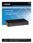
1
LGC220AE Gigabit Media Converter User’s Manual BLACK BOX ® Link 10/100/1000BASE-T to 100-/1000-Mbps SFP fiber connections. Customer Support Information Order toll-free in the U.S.: Call 877-877-BBOX (outside U.S. call 724-746-5500) FREE technical support 24 hours a day, 7 days a week: Call 724-746-5500 or fax 724-746-0746 Mailing address: Black Box Corporation, 1000 Park Drive, Lawrence, PA 15055-1018 Web site: www.blackbox.com • E-mail: [email protected] Trademarks Used in this Manual Trademarks Used in this Manual Black Box and the Double Diamond logo are registered trademarks of BB Technologies, Inc. Microsoft, Windows, and Internet Explorer are registered trademarks of Microsoft Corporation. Mozilla and Firefox are registered trademarks of the Mozilla Foundation. Google and Chrome are registered trademarks of Google, Inc. Any other trademarks mentioned in this manual are acknowledged to be the property of the trademark owners. We‘re here to help! If you have any questions about your application or our products, contact Black Box Tech Support at 724-746-5500 or go to blackbox.com and click on “Talk to Black Box.” You’ll be live with one of our technical experts in less than 60 seconds. Page 2 724-746-5500 | blackbox.com FCC and IC RFI Statements Federal Communications Commission and Industry Canada Radio Frequency Interference Statements This equipment generates, uses, and can radiate radio-frequency energy, and if not installed and used properly, that is, in strict accordance with the manufacturer’s instructions, may cause interference to radio communication. It has been tested and found to comply with the limits for a Class A computing device in accordance with the specifications in Subpart B of Part 15 of FCC rules, which are designed to provide reasonable protection against such interference when the equipment is operated in a commercial environment. Operation of this equipment in a residential area is likely to cause interference, in which case the user at his own expense will be required to take whatever measures may be necessary to correct the interference. Changes or modifications not expressly approved by the party responsible for compliance could void the user’s authority to operate the equipment. This digital apparatus does not exceed the Class A limits for radio noise emission from digital apparatus set out in the Radio Interference Regulation of Industry Canada. Le présent appareil numérique n’émet pas de bruits radioélectriques dépassant les limites applicables aux appareils numériques de la classe A prescrites dans le Règlement sur le brouillage radioélectrique publié par Industrie Canada. 724-746-5500 | blackbox.com Page 3 NOM Statement Instrucciones de Seguridad (Normas Oficiales Mexicanas Electrical Safety Statement) 1. T odas las instrucciones de seguridad y operación deberán ser leídas antes de que el aparato eléctrico sea operado. 2. Las instrucciones de seguridad y operación deberán ser guardadas para referencia futura. 3. Todas las advertencias en el aparato eléctrico y en sus instrucciones de operación deben ser respetadas. 4. T odas las instrucciones de operación y uso deben ser seguidas. 5. E l aparato eléctrico no deberá ser usado cerca del agua—por ejemplo, cerca de la tina de baño, lavabo, sótano mojado o cerca de una alberca, etc. 6. E l aparato eléctrico debe ser usado únicamente con carritos o pedestales que sean recomendados por el fabricante. 7. El aparato eléctrico debe ser montado a la pared o al techo sólo como sea recomendado por el fabricante. 8. S ervicio—El usuario no debe intentar dar servicio al equipo eléctrico más allá a lo descrito en las instrucciones de operación. Todo otro servicio deberá ser referido a personal de servicio calificado. 9. El aparato eléctrico debe ser situado de tal manera que su posición no interfiera su uso. La colocación del aparato eléctrico sobre una cama, sofá, alfombra o superficie similar puede bloquea la ventilación, no se debe colocar en libreros o gabinetes que impidan el flujo de aire por los orificios de ventilación. 10. E l equipo eléctrico deber ser situado fuera del alcance de fuentes de calor como radiadores, registros de calor, estufas u otros aparatos (incluyendo amplificadores) que producen calor. 11. E l aparato eléctrico deberá ser connectado a una fuente de poder sólo del tipo descrito en el instructivo de operación, o como se indique en el aparato. 12. P recaución debe ser tomada de tal manera que la tierra fisica y la polarización del equipo no sea eliminada. 13. L os cables de la fuente de poder deben ser guiados de tal manera que no sean pisados ni pellizcados por objetos colocados sobre o contra ellos, poniendo particular atención a los contactos y receptáculos donde salen del aparato. 14. El equipo eléctrico debe ser limpiado únicamente de acuerdo a las recomendaciones del fabricante. 15. E n caso de existir, una antena externa deberá ser localizada lejos de las lineas de energia. 16. El cable de corriente deberá ser desconectado del cuando el equipo no sea usado por un largo periodo de tiempo. 17. Cuidado debe ser tomado de tal manera que objectos liquidos no sean derramados sobre la cubierta u orificios de ventilación. 18. S ervicio por personal calificado deberá ser provisto cuando: A: El cable de poder o el contacto ha sido dañado; u B: Objectos han caído o líquido ha sido derramado dentro del aparato; o C: El aparato ha sido expuesto a la lluvia; o D: El aparato parece no operar normalmente o muestra un cambio en su desempeño; o E: El aparato ha sido tirado o su cubierta ha sido dañada. Page 4 724-746-5500 | blackbox.com Product Safety Product Safety WARNING: To use this product safely, we recommend that you read this appendix before installing and using this product. Failure to follow these precautions and warnings might cause product malfunction, electrical shock, or even fire. If this product is working abnormally (e.g. generating smoke), please stop using this product and contact Black Box Technical Support at 724-746-5500 or [email protected]. DO NOT install this product under conditions listed below: • DO NOT install this product in an environment with conditions exceeding its specified operating environment. • DO NOT install this product in an environment that is subjected to direct sunlight or near any heating equipment. • DO NOT install this product in an environment with extreme temperature changes. Extreme temperature changes, even within the product’s operating temperature range, may cause malfunctions. • DO NOT install this product in a location near any sources of water or liquid. • DO NOT stack this product with other network devices directly on top of one another. Stacking network devices directly without applying a mounting rack will cause this product to overheat. • DO NOT install this product on an unstable surface. Doing so might cause this product to fall, resulting in malfunction. Product Maintenance Guide: • DO NOT disassemble this product. Doing so might cause malfunction and void your product’s warranty. •W e recommend that you keep your product clear of dust. To remove dust from your product, use a dry brush and brush it off gently. •W hen not using this product, store it in an environment with low humidity, cool temperature, and free of dust. Failure to do so might cause malfunction. •B efore powering up this product, make sure that the electric power source meets this product’s requirement. DO NOT use other power adapters. 724-746-5500 | blackbox.com Page 5 Table of Contents Table of Contents 1. Specifications..........................................................................................................................................................................7 2. Overview................................................................................................................................................................................8 2.1 Introduction....................................................................................................................................................................8 2.2 Features..........................................................................................................................................................................8 2.3 What’s Included.............................................................................................................................................................8 2.4 Hardware Description.....................................................................................................................................................9 3. Preparing for Management.................................................................................................................................................. 10 3.1 Preparation for the Web Interface................................................................................................................................ 10 3.2 Preparation for the Telnet Interface.............................................................................................................................. 11 4. Configuration via the Web User Interface............................................................................................................................ 13 4.1 Network Information.................................................................................................................................................... 13 4.2 Local Setting................................................................................................................................................................. 13 4.2.1 IP Configuration................................................................................................................................................... 13 4.2.2 Password Setting................................................................................................................................................. 14 4.2.3 Converter Configuration...................................................................................................................................... 14 4.2.4 Port Configuration.............................................................................................................................................. 15 4.2.5 MIB Counter........................................................................................................................................................ 16 4.2.6 SNMP Configuration........................................................................................................................................... 16 4.2.7 VLAN................................................................................................................................................................... 17 4.2.8 Q-in-Q................................................................................................................................................................. 18 4.2.9 Port Policy........................................................................................................................................................... 19 4.2.10 CoS Policy.......................................................................................................................................................... 19 4.3 Remote Setting.............................................................................................................................................................20 4.3.1 802.3ah Function................................................................................................................................................20 4.3.2 Loopback Test.....................................................................................................................................................20 4.3.3 802.3ah Status.................................................................................................................................................... 21 4.4 Tools............................................................................................................................................................................. 21 4.4.1 System Reboot.................................................................................................................................................... 21 4.4.2 Save and Restore................................................................................................................................................. 21 4.4.3 Firmware Upgrade..............................................................................................................................................22 5. Telnet ..............................................................................................................................................................................23 5.1 Telnet Overview............................................................................................................................................................23 5.2 Network Information....................................................................................................................................................23 5.3 Configure Local............................................................................................................................................................ 24 5.3.1 IP Configuration...................................................................................................................................................24 5.3.2 Restore Factory Default.......................................................................................................................................25 5.3.3 Save Configure....................................................................................................................................................25 5.3.4 Reset...................................................................................................................................................................25 5.4 802.3ah OAM Function................................................................................................................................................26 5.4.1 802.3ah Configuration........................................................................................................................................26 5.4.2 Loopback Test.....................................................................................................................................................26 5.5 MIB Counter.................................................................................................................................................................27 5.6 Close Connection.........................................................................................................................................................27 Appendix. IP Configuration for Your PC.....................................................................................................................................28 Page 6 724-746-5500 | blackbox.com Chapter 1: Specifications 1. Specifications Approvals Certifications: FCC Class A, CE, EMC safety Class A; Standards: IEEE 802.3a, IEEE 802.3u, IEEE 802.3z, IEEE 802.3x flow control Data Transfer Rate 2000 Mbps, full-duplex Transmission Media Twisted-pair: 1000BASE-T CAT5/5e/6 UTP/STP, up to 328 feet (100 m) Connectors (1) RJ-45, (1) SFP cage Indicators RJ-45 port: (1) 100 Mbps/Act, 1000 Mbps/Act. LED; SFP port: (1) Link/Act LED; Per unit: (1) Power LED Environment Temperature Tolerance: Operating: 32 to 122° F (0 to 50° C), Storage: -4 to +194° F (-20 to +90 C); Humidity: 10 to 90%, noncondensing Power 5-VDC 2A power supply, or powered by USB 2.0 interface; Consumption: 10 watts DImensions 0.9"H x 2.9"W x 4"D (2.2 x 7.4 x 10.2 cm) Weight 0.5 lb. (0.2 kg) 724-746-5500 | blackbox.com Page 7 Chapter 2: Overview 2. Overview 2.1 Introduction The Gigabit Media Converter links 10/100/1000BASE-T to 100-/1000-Mbps SFP fiber connections. You can manage it via an intuitive configuration Web page. This media converter's SFP port supports both Fast Ethernet (155 Mbps) and Gigabit Ethernet (1.25 Gbps) compatible SFP modules. If the media converter's SFP supports dual-speed mode, you can change the unit's transmit rate via the Web configuration user interface (UI). Table 2-1. SFP port speeds. SFP Type Web UI Single Speed 100M SFP Port Configuration — Mode 100 M Dual Speed 1000M SFP √ √ 1000 M 100/1000M SFP √ √ Table 2-2. Compatible SFP Modules. Product Code Description LFP401 SFP, 155-Mbps Fiber with Extended Diagnostics, 850-nm Multimode, LC, 2 km LFP402 SFP, 155-Mbps Fiber with Extended Diagnostics, 1310-nm Multimode, LC, 2 km LFP403 SFP, 155-Mbps Fiber with Extended Diagnostics, 1310-nm, Single-Mode, LC, 30 km LFP404 SFP, 155-Mbps Fiber with Extended Diagnostics, 1310-nm Single-Mode, Plus, LC, 60 km LFP411 SFP, 1.25-Gbps Fiber with Extended Diagnostics, 850-nm Multimode, LC, 300 m LFP412 SFP, 1.25-Gbps Fiber with Extended Diagnostics, 1310-nm Multimode, LC, 2 km LFP413 SFP, 1.25-Gbps Fiber with Extended Diagnostics, 1310-nm Single-Mode, LC, 10 km LFP414 SFP, 1.25-Gbps Fiber with Extended Diagnostics, 1310-nm Single-Mode, LC, 30 km LFP416 SFP with SGMII Interface, 1.25 Gbps, Copper, 10/100/1000BASE-T, Extended Diagnostics LFP431 SFP, 155-Mbps/1.25 Gbps Dual-Rate, Single-Fiber Bidirectional, LC 2.2 Features •C omplies with IEEE 802.3ab 1000BASE-T, IEEE 802.3u 100BASE-BX U, and IEEE 802.3z 1000BASE-BX-U Gigabit Ethernet standards. • Has one 10/100/1000BASE-T Gigabit Ethernet port and one SFP slot that supports both Fast Ethernet (155 Mbps) and Gigabit Ethernet (1.25 Gbps) compatible SFP modules. • Twisted-pair port supports full-duplex, auto-MDI/MDI-X, and autonegotiation. • Web Smart function supports SNMP, 802.1Q VLAN, Q-in-Q, 802.1p CoS, 802.3ahd OAM and HTTP, Ping. • Provides link loss forwarding and 9.6 K jumbo frame support. 2.3 What's Included Your package should contain the following items. If anything is missing or damaged, contact Black Box Technical Support at 724-746-5500 or [email protected]. • 10/100/1000BASE-T to 100-/1000-Mbps SFP Media Converter • Power adapter • USB cable Page 8 724-746-5500 | blackbox.com Chapter 2: Overview To download this user manual from the Black Box Web site: 1. Go to www.blackbox.com 2. Enter the part number (LGC220AE) in the search box: 3. Click on the “Resources” tab on the product page, and select the document you wish to download. 2.4 Hardware Description Figure 2-1 shows the 10/100/1000BASE-T to 100-/1000-Mbps SFP Media Converter. Table 2-3 describes its components. 5 4 3 1 2 Figure 2-1. Media converter. Table 2-3. Media converter components. Number in Fig. 2-1 Component Description 1 RJ-45 connector Links to 10/100/1000BASE-T device 2 TP port LEDs 1000 Mbps and Link/Act LEDs 3 SFP slot Houses SFP module 4 SFP port LEDs Link/Act LEDs 5 Power LED Lights when power is on 6 (on back of unit) Power connector Links to optional 5-VDC, 10-watt power supply* *The media converter can also be powered by the USB 2.0 interface. 724-746-5500 | blackbox.com Page 9 Chapter 3: Preparing for Management 3. Preparing for Management You can remotely manage this media converter via Telnet® or a Web browser (such as Microsoft® Internet Explorer® or Mozilla® Firefox®) to access and configure the media converter from anywhere on the network. 3.1 Preparation for Web Interface The Web management page allows you to use a standard web browser (such as Microsoft Internet Explorer, Google® Chrome® or Mozilla Firefox) to access and configure the media converter from anywhere on the network. Before you attempt to use the Web user interface to manage media converter operation, verify that your media converter is properly installed on your network and that every PC on this network can access the media converter via the Web browser. 1. Verify that your network interface card (NIC) is operational, and that your operating system supports TCP/IP protocol. 2. Power up the media converter power and connect your computer to the media converter. 3. T he media converter default IP address is 192.168.2.1. The media converter and the connected PC should be located within the same IP Subnet. 4. C hange your computer's IP address to 192.168.2.XX or other IP address that is located in the 192.168.2.x subnet (For example: IP Address: 192.168.2.30; Subnet Mask: 255.255.255.0). Figure 3-1. TCP/IP screen. 5. Launch the Web browser on the PC. 6. Type http://192.168.2.1 (or the IP address of the media converter). And then press Enter. 7. The login screen will appear next. See Figure 3-2. Page 10 724-746-5500 | blackbox.com Chapter 3: Preparing for Management ' Figure 3-2. Login screen. 8. Type in the username and password. The default username and password are both admin. The Welcome page appears. Figure 3-3. Welcome page. If you can't login to the media converter, the following steps can help you to identify the problem. 1. In DOS command mode, type "ipconfig" to check the NIC's setting. Type the "ping 192.168.2.1" to verify a normal response time. 2. Check the security and firewall settings of your computer. 3. Try a different Web browser. 4. Clear your Web browser’s browsing history. For more information, refer to the Appendix: IP Configuration for Your PC. 3.2 Preparation for Telnet Interface If your Windows® OS is Win XP, Win 2000 or early version, you can access the Telnet console by the default command. If your OS is Windows 7 or a later version, please download the terminal tool, such as HyperTerminal or Putty. To connect via Telnet: 1. Go to Start -> Run -> cmd. Then press Enter. 2. Type the telnet 192.168.2.1 address (or the IP address of the media converter). Then press Enter. 724-746-5500 | blackbox.com Page 11 Chapter 3: Preparing for Management Access Telnet with Putty: 1. Open Telnet/PuTTY Choose Telnet in the Protocol field, and in the Session configuration, enter the Host Name (IP Address of your media converter, default value is 192.168.2.1) and Port number (default Telnet =23, SSH = 22). Then click on “Open” to start the PuTTy session console. Figure 3-4. PuTTy configuration screen. After you click on Open, you can see the cipher information in the popup screen. Press Yes to accept the Security Alert. 3. You are now in the media converter’s telnet configuration interface. Figure 3-5. Telnet interface screen. Page 12 724-746-5500 | blackbox.com Chapter 4: Configuration via the Web User Interface 4. Configuration via the Web User Interface After you login to the media converter’s configuration Web page, you can configure the settings or monitor system status. Click the menu button in the left side of the Web page to open the function pages. 4.1 Network Information Figure 4-1. Network Information screen. You can view system information here in Network Information, including MAC, IP, gateway, subnet mask address, software version, and device description. You can also enable/disable Remote Device Control. If enabled, you can configure the device and view its information remotely. 4.2 Local Setting You can configure the media converter locally here in the Local Setting. 4.2.1 IP Configuration Figure 4-2. IP Configuration screen. This media converter embeds a DHCP client. You can enable/disable this function on this page. If DHCP is disabled, you will have to set the IP, gateway, and subnet mask manually. If DHCP is enabled, the media converter will get a set of IP, subnet mask, and gateway information automatically from the DHCP server. You can also set the description for your media converter here. 724-746-5500 | blackbox.com Page 13 Chapter 4: Configuration via the Web User Interface 4.2.2 Password Setting Figure 4-3. Password Setting screen. You can set a new password for the media converter’s configuration Web page here. The password must be alphanumeric characters (“a” – ”z”, “A” – “Z”, “0” – “9”, and “_”) and is case-sensitive. You must input the old password when setting a new password. Press the “Apply” button to apply the changes you’ve made. For security issues, you cannot change the login name. 4.2.3 Converter Configuration Figure 4-4. Converter configuration screen. Page 14 724-746-5500 | blackbox.com Chapter 4: Configuration via the Web User Interface Table 4-1. Converter Configuration screen options. Option Description Jumbo Frame (9K) Enable this function for Jumbo Frame packet (9K) transmitting. Link Transparent To enable Remote Fault Detect and Link Loss Carry Forward functions, select this option. Remote Fault Detect When enabled, the fiber port will be able to receive OAM packets. The media converter will set local RJ-45 port link up/down according to the remote media converter’s RJ-45 port’s link status. NOTE: T he Link Transparent function must be enabled for Remote Fault Detect to take effect. Link Loss Carry Forward When enabled, the fiber port link will be down when the RJ-45 port link is down, and the fiber port will resume connection when the RJ-45 port’s connection is back on. NOTE: T he Link Transparent function must be enabled for Link Loss Carry Forward to take effect. Forward CRC Error Frame Packets with CRC error will still be transmitted if this function is enabled. If this function is disabled, packets with CRC error will be dropped instead. Forward Pause Frame The media converter will forward pause frames and regard them as normal packets if this function is enabled. Management Packet High Priority QoS will be enabled if this function is enabled. Four queues will be enabled, and queue 3’s priority will be set to “strict.” All management packets, such as 802.3ah OAM, SNMP packets will be in queue 3 to guarantee bandwidth. Broadcast Storm Filter, Multicast Storm Filter, Unknown DA Unicast Storm Filter When too many broadcast/multicast/unknown DA unicast packets arrive in a period time, the media converter will drop these packets if this function is enabled. 4.2.4 Port Configuration Figure 4-5. Port Configuration screen. You can set the media converter’s port transmitting/receiving rate, flow control function, ingress/egress rate limit on this page. Also, you can set the ingress/egress rate limit. 724-746-5500 | blackbox.com Page 15 Chapter 4: Configuration via the Web User Interface NOTE: The rate limit you set here must be the multiple of 64. If the rate limit you input is not the multiple of 64, it will be set to 64 automatically. Press the “Apply” button to apply all the settings you’ve configured here. 4.2.5 MIB Counters Figure 4-6. MIB Counters screen. You can view the media converter’s MIB counters in this page. Press the “Clear” button to reset all counters to zero, or press the “Refresh” button to refresh the page. 4.2.6 SNMP Configuration Figure 4-7. SNMP Configuration screen. You can make SNMP settings on this page. Table 4-2. SNMP settings. Option Description SNMP Ability Enable or Disable SNMP functions. Trap Mode SNMP will send trap event to SNMP server if this function is enabled. SNMP Trap IP Address SNMP Server IP address. All SNMP trap events will be sent to the IP you set here. Page 16 724-746-5500 | blackbox.com Chapter 4: Configuration via the Web User Interface 4.2.7 VLAN VLAN Group Figure 4-8. VLAN Group screen. You can set 16 VLAN entries if this function is enabled. Each VLAN entry contains its VID and member port. Press the “Apply” button to apply all the settings you’ve made here. VLAN Per Port Setting Figure 4-9. VLAN Per Port Setting screen. You can set each port’s PVID and its egress tag behavior on this page. Table 4-3. VLAN per port settings screen options. Egress Link Type Description Replace Tag The media converter will remove VLAN tags from packets and add new tags. The tag inserted will be the ingress port’s “Default Tag,” which is indexed by port “Port based VLAN index.” This is replacement processing for tagged packets and insertion for untagged packets. Remove Tag The media converter will remove VLAN tags from packets if these packets are tagged during transmission. The media converter will not modify packets received without tags. Add Tag The media converter will add VLAN tags to packets if these packets are not tagged during transmission. The media converter will not add tags to packets already tagged. The inserted tag is the ingress port’s “Default tag,” which is indexed by the port’s “Port based VLAN index..” 724-746-5500 | blackbox.com Page 17 Chapter 4: Configuration via the Web User Interface Table 4-3 (continued). VLAN per port settings screen options. Egress Link Type Description Don’t Touch Tag The media converter will not insert or remove VLAN tags to/from packets transmitting through this port. Port VLAN Entry Select Port base VLAN index. The number means VLAN table entry index, not VID. Ingress Filter Enable or disable VLAN ingress filter. Press the “Apply” button to apply the settings. 4.2.8 Q-in-Q Figure 4-10. Q-in-Q Functions Configuration screen. You can set the Q-in-Q function on this page. Table 4-4. Q-in-Q functions. Function Description Q in Q Enable Enable/disable the Q-in-Q function. Out Layer VLAN Tag User defined Q-in-Q out layer VLAN tag Ether type. Out Layer VLAN VID User defined Q-in-Q out layer VLAN tag VID. VLAN Tag Priority decision Decide layer VLAN Tag’s priority, use internal VLAN tag’s priority or remark 802.1p decision priority. Q in Q direction Select Q in Q direction, which port adds tag, and which port removes tag. Press the “Apply” button to apply the settings. Page 18 724-746-5500 | blackbox.com Chapter 4: Configuration via the Web User Interface 4.2.9 Port Policy Figure 4-11. Port to Queue screen. You can set the priorities of each physical port here in this page. When a packet without VLAN tag is received from the connection port, it will be handled according to the priority value you set here. Press the “Apply” button to apply the settings. 4.2.10 CoS Policy Figure 4-12. CoS policy screen. Each port of the media converter contains four queues. Queue 3 has the highest priority, while queue 0 has the lowest priority. When receiving VLAN and IEEE 802.1p priority tagged packets, the media converter will handle these packets accordingly. Press the “Apply” button to apply the settings. 724-746-5500 | blackbox.com Page 19 Chapter 4: Configuration via the Web User Interface 4.3 Remote Setting 4.3.1 802.3ah Function 802.3ah Configuration Figure 4-13. 802.3ah Configuration screen. You can set 802.3ah OAM in this page. Enable/disable 802.3ah function and set its mode as passive or active mode. Press the “Apply” button to apply the settings. 4.3.2 Loopback Test Figure 4-14. 802.3ah Loopback test. You can start 802.3ah loopback test here on this Web page, with the number of packets and packet length value you set. Press the “Apply” button to apply the settings. Page 20 724-746-5500 | blackbox.com Chapter 4: Configuration via the Web User Interface 4.3.3 802.3ah Status You can view IEEE 802.3ah status on this Web page. Figure 4-15. IEEE 802.3ah status screen. 4.4 Tools 4.4.1 System Reboot Press the “System Reboot” button to restart the system. All settings will be kept. 4.4.2 Save and Restore Figure 4-16. Configuration Setting screen. Table 4-5. Save and Restore settings. Setting Description Backup Save all the settings of the media converter to a file. Restore Restore all the settings of the media converter from a pre-saved configuration file. Factory Set all parameters to the factory default value. 724-746-5500 | blackbox.com Page 21 Chapter 4: Configuration via the Web User Interface 4.4.3 Firmware Upgrade Figure 4-17. Firmware Upgrade screen. You can update the media converter’s firmware in this Web page. Press the “Browse…” button to select the firmware from your PC, then press the “Update” button to start updating the firmware. NOTE: It might take 60 seconds to update the firmware. Do not interrupt this process or your media converter might malfunction. Page 22 724-746-5500 | blackbox.com Chapter 5: Telnet 5. Telnet Telnet provides another way to configure your media converter. 5.1 Telnet Overview Figure 5-1. Telnet screen. As mentioned in Chapter 3, Preparing for Management, telnet provides another way to configure your media converter if your PC doesn’t have access to a Web page. To make configurations or view system status, input the number of the option you would like to perform. If you’re having trouble connecting to the configuration interface via telnet, refer to Section 3.2, Preparation for Telnet Interface. 5.2 Network Information Figure 5-2. Network Information screen. You can view your media converter’s port link status by typing “1” in the telnet interface. To view other status/information, type “2” in the telnet interface. Information displayed here includes MAC, IP, gateway, subnet mask address, software version number, and device description. 724-746-5500 | blackbox.com Page 23 Chapter 5: Telnet 5.3 Configure Local Figure 5-3. Configure Local screen. To enter the “Configure Local” sub-menu, type “3” in the telnet interface. To refresh the menu, type “0” in the telnet interface. To leave this sub-menu, press the escape key on your keyboard. 5.3.1 IP Configuration Figure 5-4. IP Configuration screen. You can set the media converter’s IP address by typing “1” in the “Configure Local” sub-menu. After you type “1”, the system will prompt you to input the IP address in the format of “X.X.X.X” Page 24 724-746-5500 | blackbox.com Chapter 5: Telnet 5.3.2 Restore Factory Default Figure 5-5. Restore Factory Default screen. To reset the media converter’s settings to their default values, type “2” in the “Configure Local” sub-menu. 5.3.3 Save Configure Figure 5-6. Save Configure screen. To save your media converter’s current settings, type “3” in the “Configure Local” sub-menu. 5.3.4 Reset Figure 5-7. Reset screen. To reboot your media converter, type “4” in the “Configure Local” sub-menu. 724-746-5500 | blackbox.com Page 25 Chapter 5: Telnet 5.4 802.3ah OAM Function To enter the “802.3ah OAM Function” sub-menu, type “4” in the telnet interface. To refresh the menu, type “0” in the telnet interface. To leave this sub-menu, press the escape key on your keyboard. 5.4.1 802.3ah Configuration Figure 5-8. 802.3ah Configuration screen. You can configure IEEE 802.3ah OAM function as shown in the figure above. 5.4.2 Loopback Test Figure 5-9. Loopback test screen. Start the loopback test here as shown in the figure above. Page 26 724-746-5500 | blackbox.com Chapter 5: Telnet 5.5 MIB Counter To view the media converter’s MIB counters, type “5” in the telnet interface. Figure 5-10. MIB Counter screen. 5.6 Close Connection To disconnect the telnet connection, type “6” in the telnet interface. 724-746-5500 | blackbox.com Page 27 Appendix: IP Configuration for Your PC Appendix. IP Configuration for Your PC This appendix describes how to set the IP address of your PC so you can connect to the configuration Web page. The configuration Web page allows you to set system variables or monitor system status. The following section will show you how to set the IP address properly in a Microsoft Windows 8 environment. Setting IP address in other Microsoft operating system (such as Windows Vista® or Windows 7) is similar. 1. Open “Network and Sharing Center" in Control Panel, and click on "Change adapter settings" as shown in Figure A-1. Figure A-1. Change adapter settings option. 2. A "Network Connections" window will pop up, showing all the network connections available on your PC. Double-click on the network connection you are using to connect the media converter. Figure A-2. Network Connections screen. Page 28 724-746-5500 | blackbox.com Appendix: IP Configuration for Your PC 3. An Ethernet Status window will pop up. Click on the Properties button as shown in Figure A-3. Figure A-3. Ethernet status screen. 724-746-5500 | blackbox.com Page 29 Appendix: IP Configuration for Your PC 4. An Ethernet Properties window will pop up. Double click on the Internet Protocol Version 4 (TCP/IPv4). Figure A-4. Select Internet Protocol Version 4 (TCP/IPv4). Page 30 724-746-5500 | blackbox.com Appendix: IP Configuration for Your PC 5. A n Internet Protocol Version 4 (TCP/IPv4) Properties window will pop up. Set your PC’s IP address and subnet mask as shown in Figure A-5. By default, your product’s IP address should be 192.168.2.1.You can set any IP address for your PC as long as it’s not the same as your media converter's IP address and is in the same network segment as your media converter’s IP address. Press OK to apply the TCP/IPv4 settings. Connect to your media converter using a Web browser (i.e. Internet Explorer, Chrome, or Firefox). Figure A-5. Internet Protocol Version 4 Properties screen. 724-746-5500 | blackbox.com Page 31 Black Box Tech Support: FREE! Live. 24/7. Tech support the way it should be. Great tech support is just 60 seconds away at 724-746-5500 or blackbox.com. About Black Box Black Box provides an extensive range of networking and infrastructure products. You’ll find everything from cabinets and racks and power and surge protection products to media converters and Ethernet switches all supported by free, live 24/7 Tech support available in 60 seconds or less. © Copyright 2014. Black Box Corporation. All rights reserved. Black Box® and the Double Diamond logo are registered trademarks of BB Technologies, Inc. Any third-party trademarks appearing in this manual are acknowledged to be the property of their respective owners. LGC220AE user manual, version 1 724-746-5500 | blackbox.com