1
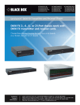
LB323A Industrial Ethernet Extender for Extreme Temperatures - 10/100, 1-Port User Manual Customer Support Information Order toll-free in the U.S.: Call 877-877-BBOX (outside U.S. call 724-746-5500) FREE technical support 24 hours a day, 7 days a week: Call 724-746-5500 or fax 724-746-0746 www.blackbox.com • [email protected] Trademarks Used in this Manual Trademarks Used in this Manual Black Box and the Double Diamond logo are registered trademarks of BB Technologies, Inc. Any other trademarks mentioned in this manual are acknowledged to be the property of the trademark owners. We‘re here to help! If you have any questions about your application or our products, contact Black Box Tech Support at 724-746-5500 or go to blackbox.com and click on “Talk to Black Box.” You’ll be live with one of our technical experts in less than 60 seconds. Page 2 724-746-5500 | blackbox.com FCC and IC RFI Statements Federal Communications Commission and Industry Canada Radio Frequency Interference Statements This equipment generates, uses, and can radiate radio-frequency energy, and if not installed and used properly, that is, in strict accordance with the manufacturer’s instructions, may cause interference to radio communication. It has been tested and found to comply with the limits for a Class A computing device in accordance with the specifications in Subpart B of Part 15 of FCC rules, which are designed to provide reasonable protection against such interference when the equipment is operated in a commercial environment. Operation of this equipment in a residential area is likely to cause interference, in which case the user at his own expense will be required to take whatever measures may be necessary to correct the interference. Changes or modifications not expressly approved by the party responsible for compliance could void the user’s authority to operate the equipment. This digital apparatus does not exceed the Class A limits for radio noise emission from digital apparatus set out in the Radio Interference Regulation of Industry Canada. Le présent appareil numérique n’émet pas de bruits radioélectriques dépassant les limites applicables aux appareils numériques de la classe A prescrites dans le Règlement sur le brouillage radioélectrique publié par Industrie Canada. Disclaimer: Black Box Network Services shall not be liable for damages of any kind, including, but not limited to, punitive, consequential or cost of cover damages, resulting from any errors in the product information or specifications set forth in this document and Black Box Network Services may revise this document at any time without notice. 724-746-5500 | blackbox.com Page 3 NOM Statement Instrucciones de Seguridad (Normas Oficiales Mexicanas Electrical Safety Statement) 1. T odas las instrucciones de seguridad y operación deberán ser leídas antes de que el aparato eléctrico sea operado. 2. Las instrucciones de seguridad y operación deberán ser guardadas para referencia futura. 3. Todas las advertencias en el aparato eléctrico y en sus instrucciones de operación deben ser respetadas. 4. T odas las instrucciones de operación y uso deben ser seguidas. 5. E l aparato eléctrico no deberá ser usado cerca del agua—por ejemplo, cerca de la tina de baño, lavabo, sótano mojado o cerca de una alberca, etc. 6. E l aparato eléctrico debe ser usado únicamente con carritos o pedestales que sean recomendados por el fabricante. 7. El aparato eléctrico debe ser montado a la pared o al techo sólo como sea recomendado por el fabricante. 8. S ervicio—El usuario no debe intentar dar servicio al equipo eléctrico más allá a lo descrito en las instrucciones de operación. Todo otro servicio deberá ser referido a personal de servicio calificado. 9. El aparato eléctrico debe ser situado de tal manera que su posición no interfiera su uso. La colocación del aparato eléctrico sobre una cama, sofá, alfombra o superficie similar puede bloquea la ventilación, no se debe colocar en libreros o gabinetes que impidan el flujo de aire por los orificios de ventilación. 10. E l equipo eléctrico deber ser situado fuera del alcance de fuentes de calor como radiadores, registros de calor, estufas u otros aparatos (incluyendo amplificadores) que producen calor. 11. E l aparato eléctrico deberá ser connectado a una fuente de poder sólo del tipo descrito en el instructivo de operación, o como se indique en el aparato. 12. P recaución debe ser tomada de tal manera que la tierra fisica y la polarización del equipo no sea eliminada. 13. L os cables de la fuente de poder deben ser guiados de tal manera que no sean pisados ni pellizcados por objetos colocados sobre o contra ellos, poniendo particular atención a los contactos y receptáculos donde salen del aparato. 14. El equipo eléctrico debe ser limpiado únicamente de acuerdo a las recomendaciones del fabricante. 15. E n caso de existir, una antena externa deberá ser localizada lejos de las lineas de energia. 16. El cable de corriente deberá ser desconectado del cuando el equipo no sea usado por un largo periodo de tiempo. 17. Cuidado debe ser tomado de tal manera que objectos liquidos no sean derramados sobre la cubierta u orificios de ventilación. 18. S ervicio por personal calificado deberá ser provisto cuando: A: El cable de poder o el contacto ha sido dañado; u B: Objectos han caído o líquido ha sido derramado dentro del aparato; o C: El aparato ha sido expuesto a la lluvia; o D: El aparato parece no operar normalmente o muestra un cambio en su desempeño; o E: El aparato ha sido tirado o su cubierta ha sido dañada. Page 4 724-746-5500 | blackbox.com Table of Contents Table of Contents Quick Start Guide.........................................................................................................................................................................6 1. Specifications..........................................................................................................................................................................8 2. Overview.............................................................................................................................................................................. 10 2.1 Introduction.................................................................................................................................................................. 10 2.2 Features........................................................................................................................................................................ 10 2.3 What's Included........................................................................................................................................................... 10 2.4 Hardware Description................................................................................................................................................... 11 3. Installation............................................................................................................................................................................ 13 3.1 Preparing the Site......................................................................................................................................................... 13 3.2 Installing the Industrial Ethernet Extender.................................................................................................................... 13 3.3 Connecting to the 10/100 Mbps RJ-45 Port................................................................................................................ 13 3.4 Connecting to the Ethernet Extender Port................................................................................................................... 14 3.5 Checking the Installation.............................................................................................................................................. 14 3.6 Applying DC Power...................................................................................................................................................... 14 4. Troubleshooting.................................................................................................................................................................... 16 4.1 Troubleshooting Tips.................................................................................................................................................... 16 4.2 Additional Troubleshooting Suggestions...................................................................................................................... 17 4.2.1 Configuration...................................................................................................................................................... 17 4.2.2 Industrial Ethernet Extender Integrity.................................................................................................................. 17 4.2.3 Auto-Negotiation................................................................................................................................................ 17 724-746-5500 | blackbox.com Page 5 Quick Start Guide Quick Start Guide Unpacking Unpack the items. Your package should include: • One LB323A Hardened Industrial Ethernet Extender • This printed quick start guide If items are missing or damaged, contact Black Box Technical Support at 724-746-5500 or [email protected]. Keep the carton and packing material. 2. Select a Location • Installation: Desktop, Wallmount, DIN-Rail mount. • Identify a power source within 6 feet (1.8 meters). •C hoose a dry area with ambient temperature between -40 and +167º F (-40 and +75° C). •K eep away from heat sources, sunlight, warm air exhausts, hot-air vents, and heaters. • Be sure there is adequate airflow. •K eep the device at least 6-ft. (1.8-m) away from the nearest source of electromagnetic noise, such as a photocopy machine. 3. Connect to the Data Ports 1. Insert one end of the Ethernet cable into a switch port. 2. Connect the other end into the Ethernet port of the device. 3. Insert the voice grade copper wire between one pair of Hardened Ethernet Extenders via the Ethernet Extender port (RJ-11 connector or terminal block). Figure 1. Front and top views of the extender. Page 6 724-746-5500 | blackbox.com Quick Start Guide Table 1. LEDs on the extender. LED Color Status Power 1, 2 Green ON = Receiving power OFF = Power off Ethernet Extender Port Link Activity Green ON = Connection is established OFF = No connection is established Flashing = Port is sending or receiving data Line Speed ON = Displays the link speed in Mbps Green 10/100TX port Link/Activity Green Speed ON = Valid network connection OFF = No data transmission on port Flashing = Port is sending or receiving data Yellow ON = Link speed at 100 Mbps OFF = Link speed at 10 Mbps Apply DC Power Connect the DC power cord to the pluggable terminal block on the Hardened Ethernet Extender, and then plug it into a standard DC outlet. Next, connect the ground connection from the terminal block to the grounding surface. Figure 3. Terminal block on the extender. Table 2. DIP Switches Pin Up Down DIP Switch 1 (Site) Auto mode Local mode DIP Switch 2 (Type) Turn on link down relay Turn off link down relay Table 3. Distance and Data Rate. Distance (m) Data Rate (Mbps) 300 100 400 80 600 60 800 40 1200 20 2600 1 NOTE for Table 3: This distance/data rate information is measured according to a testing standard in the laboratory. The actual installation will be affected by the quality of the copper wire and the impact of noise disturbance. The connection speed will be affected. 724-746-5500 | blackbox.com Page 7 Chapter 1: Specifications 1. Specifications Table 1-1. Specifications Technology Standards IEEE 802.3, 10BASE-T; IEEE 802.3u, 100BASE-TX; IEEE 802.3x, full-duplex and flow control Forward and Filtering Rate 10 Mbps: 14,880 pps; 100 Mbps: 148,810 pps Processing Type Store-and-Forward, Half-duplex back pressure, and IEEE 802.3x full-duplex flow control Auto-negotiation Auto MDI/MDI-X Power Input 12 to 48 VDC (terminal block) Consumption 4.2 W max. Mechanical Casing Aluminum case, IP30 Dimensions 3.94"H x 1.65"W x 3.54"D (10 x 4.2 x 9 cm) Weight 0.9 lb. (0.41 kg) Mounting DIN-rail (top hat type 35 mm) or wallmounting Interface Connectors Ethernet Port: (1) 10/100BASE-TX port, Ethernet Extender Port: (1) RJ-11 and terminal block port; DIP Switch DIP Switch 1: Auto/Local mode, DIP Switch 2: ON/OFF LInk Down relay LED Indicators Per unit: Power 1, 2 Ethernet Extender port: Link/Activity, Line Speed; 10/100BASE-TX port: Link/Activity, Speed Page 8 724-746-5500 | blackbox.com Chapter 1: Specifications Table 1-1. Specifications (continued). Environment Operating Temperature -40 to +185° F (-40 to +85° C) Storage Temperature -40 to +185° F (-40 to +85° C) Ambient Relative Humidity 5 to 95%, noncondensing Approvals ISO Manufactured in an ISO facility Safety UL60950-1, EN60950-1 EMI FCC Part 15B, Class A; EN61000-6-4: EN55022, EN61000-3-2, EN61000-3-3 EMS EN61000-6-2: ESD Standard: EN61000-4-2; Radiated RFI Standards: EN61000-4-3; Burst Standards: EN61000-4-4; Surge Standards: EN61000-4-5; Induced RFI Standards: EN61000-4-6-8; Magnetic Field Standards: EN61000-4-8 Environmental Test Compliance Vibration Resistance: IEC60068-2-6 Fc; Shock: IEC60068-2-27; Free fall with package: FED STD 101C Method 5007.1 Table 1-2. Data Rate Specifications. Distance (feet [meters]) Data Rate (Mbps) 960 ft. (300 m) 100 Mbps 1280 ft. (400 m) 80 Mbps 1920 ft. (600 m) 60 Mbps 2560 ft. (800 m) 40 Mbps 3840 ft (1200 m) 20 Mbps 8320 ft. (2600 m) 1 Mbps 724-746-5500 | blackbox.com Page 9 Chapter 2: Overview 2. Overview 2.1 Introduction Your Industrial Ethernet Extender is a state-of-the-art IEEE-compliant network solution designed for users who require high-performance to eliminate bottlenecks and increase productivity. To simplify installation, the Industrial Ethernet Extender is shipped ready for use. 2.2. Features • Has (1) 10/100BASE-TX Ethernet port with an RJ-45 connector. • Auto negotiates speed and duplex mode on the Ethernet port. • Auto MDIX on Ethernet port. • Complies with IEEE 802.3 10BASE-T and IEEE 802.3u 100BASE-TX standards. • Has (1) Ethernet Extender port with an RJ-11 connector or terminal block. • Ethernet Extender port auto-senses the speed. •D IP switch configures Ethernet Extender Auto or Local mode, and turn OFF/ON Link Down relay. • Status LEDs. • Uses an external AC to DC power adapter (not included). 2.3 What’s Included Your package should contain the following items. If anything is missing or damaged, contact Black Box Technical Support at 724746-5500 or [email protected]. • Industrial Ethernet Extender • A printed Quick Start Guide NOTE: You will need two extenders to complete the application. The full user manual/installation guide (the document you are reading) can be downloaded from the Black Box Web site. To download from the Web site: 1. Go to www.blackbox.com 2. Enter the part number (LB323A) in the search box: 3. Click on the “Resources” tab on the product page, and select the document you wish to download. Page 10 724-746-5500 | blackbox.com Chapter 2: Overview 2.4 Hardware Description Figure 2-1 shows the front and top panels of the extender units. Tables 2-1 and 2-2 describe the extender's components. Use the extenders in pairs: one unit is configured as the local unit and the other unit is configured as the remote unit. 1 2 3 6 4 5 Figure 2-1. Front and top views of the extender. Table 2-1. Extender components. Number in Figure 2-1 Component Description 1 RJ-45 connector Links to 10/100 Mbps Ethernet. 2 LEDs Indicate status at a glance. See Table 2-3 for details. 3 RJ-11 connector Links to Ethernet line. 4 Terminal block Links to Ethernet line. 5 DIP switches Select Mode, Symmetry, and Performance. 6 Terminal block Used for power. Front Panel Features 10/100 Mbps RJ-45 Port The LB323A Industrial Ethernet Extender has one 10/100 Mbps RJ-45 port (see Figure 2‑1). This port is an auto-sensing, autoMDIX 10/100 Mbps port. When you insert a cable into an RJ-45 port, the Industrial Ethernet Extender: • Determines whether the cable is a straight-through or crossover cable. • Automatically ascertains the maximum speed (10 or 100 Mbps) and duplex mode (half- or full-duplex) of the attached device. After determining this information, the Industrial Ethernet Extender configures the RJ-45 port automatically to enable communications with the attached device, without requiring user intervention. Ethernet Extender Port The LB323A Industrial Ethernet Extender has one Ethernet Extender port (RJ-11 connector or terminal block, see Figure 2‑1). Insert the voice-grade copper wire between one pair of Ethernet Extenders via the Ethernet Extender port (RJ-11 connector or terminal block). One device must be set to LOC mode and the other to Auto mode when two devices are connected. 724-746-5500 | blackbox.com Page 11 Chapter 2: Overview LEDs The LB323A front-panel LEDs show power and link/activity status. Table 2-3 summarizes the LEDs on the Industrial Ethernet Extender. Table 1. LEDs on the extender. LED Color Status Power 1, 2 Green ON = Receiving power OFF = Power off Ethernet Extender Port Link Activity Green ON = Connection is established OFF = No connection is established Flashing = Port is sending or receiving data Line Speed ON = Displays the link speed in Mbps Green 10/100TX port Link/Activity Green Speed ON = Valid network connection OFF = No data transmission on port Flashing = Port is sending or receiving data Yellow ON = Link speed at 100 Mbps OFF = Link speed at 10 Mbps Top Panel The LB323A top panel has a terminal block for connecting up to two external power supplies (not included). Right-Side Panel The LB323A right-side panel has a product label that shows regulatory compliance, product serial number, and other information. Left-Side Panel The LB323A left-side panel shows the power input assignment. Page 12 724-746-5500 | blackbox.com Chapter 2: Overview 3. Installation 3.1 Preparing the Site Before you install your Industrial Ethernet Extender, be sure your operating environment meets the operating environment requirements in Table 3-1. Table 3-1. Site requirements. Characteristics Requirements Mounting Desktop installations: Provide a flat table or shelf surface. DIN-Rail installations: Top hat type 35 mm. Access Locate the Industrial Ethernet Extender in a position that lets you access the front-panel RJ-45 and Ethernet Extender port, view the front-panel LEDs, and access the rear-panel power connector. Power source Provide a power source within 6 feet (1.8 meters) of the installation location. Power specifications for the Industrial Ethernet Extender are shown in Chapter 1. Be sure that the AC outlet is not controlled by a wall switch, which can accidentally turn off power to the outlet and the Industrial Ethernet Extender. Environmental Temperature: Install the Industrial Ethernet Extender in a dry area, with ambient temperature between -40 to +185° F (-40 to +85° C). Keep the Industrial Ethernet Extender away from heat sources such as direct sunlight, warm air exhausts, hot-air vents, and heaters. Operating Humidity: The installation location should have a maximum relative humidity of 95%, non-condensing. Ventilation: Do not restrict airflow by covering or obstructing the rear and side panels of the Industrial Ethernet Extender. Keep at least 2 inches (5.08 centimeters) free on all sides for cooling. Operating Conditions: Keep the Industrial Ethernet Extender at least 6 ft (1.83 m) away from nearest source of electromagnetic noise, such as a photocopy machine. Stacking If you intend to stack two or more Industrial Ethernet Extenders, be sure: • The mounting surface can safely support the stack. • There is adequate space around the stack for ventilation and cooling. 3.2 Installing the Industrial Ethernet Extender You can install your Industrial Ethernet Extender on a desktop, shelf, or DIN-Rail with other equipment. If installing the Industrial Ethernet Extender on a desktop, shelf, DIN-Rail, or DIN-Rail, allow sufficient ventilation space between the device and the objects around it. The LB323A Industrial Ethernet Extender’s dimensions are: 3.94"H x 1.65"W x 3.54"D (10 x 4.2 x 9 cm) 3.3 Connecting to the 10/100 Mbps RJ-45 Port The front panel of the Industrial Ethernet Extender provides one 10/100 Mbps RJ-45 port or terminal block. To prevent ESD damage, follow normal board and component handling procedures. To connect devices to the Industrial Ethernet Extender’s 10/100 Mbps port: 1. Insert one end of a Category 5 or better Ethernet cable into a Ethernet port. 2. Insert the other cable end into the Ethernet port of a computer, printer, network storage, or other network device. 724-746-5500 | blackbox.com Page 13 Chapter 3: Installation 3.4 Connecting to the Ethernet Extender Port The front panel of the Industrial Ethernet Extender provides one RJ-11 connector or Terminal Block (see “Ethernet Extender Port” on page X). To prevent ESD damage, follow normal board and component handling procedures. To connect the Extender’s Ethernet port: Insert the voice grade copper wire between one pair of Ethernet Extenders via Ethernet Extender port (RJ-11 connector or Terminal Block). Set one device to LOC mode and the other to Auto mode when two devices are connected. Diagram Format Rule Size: 1 pt Downstream Local setting: Per Setting: AUTO Upstream Line quality is good HDMI Fiber Remote setting: Per Setting: AUTO DVI USB CATx Audio Figure 2-5. Performance mode: Use for high-speed data transmission. Diagram Format Rule Size: 1 pt Downstream Upstream Line quality is poor Local setting: Std Setting: AUTO HDMI Fiber Remote setting: Std Setting: AUTO Figure 2-6. Standard mode: Use for better noise immunity. DVI USB CATx Audio 3.5 Checking the Installation Before you apply power: • Inspect the equipment thoroughly. • Verify that all cables are installed correctly. • Check cable routing to make sure the cables are not damaged or do not create a safety hazard. • Be sure all equipment is mounted properly and securely. 3.6 Applying DC Power 1. C onnect the DC power cord to the pluggable terminal block on the Ethernet extender, and then plug it into a standard DC outlet. 2. Connect the ground connection from the terminal block to the grounding surface. When you apply power: • All green Link/Activity LEDs blink momentarily. • The green Power LED goes ON. • T he Link/Activity LEDs for every port connected to a device flash, as the Industrial Ethernet Extender conducts a brief Power On Self-Test (POST). Page 14 724-746-5500 | blackbox.com Chapter 3: Installation After the Industrial Ethernet Extender passes the POST, the Link/Activity LEDs for every port connected to a device go ON. The Industrial Ethernet Extender is now functional and ready to pass data. If the Power LED is not ON, check that the power adapter is plugged in correctly, and that the power source is good and not controlled by a wall switch. If this does not resolve the problem, see Chapter 4, Troubleshooting. 724-746-5500 | blackbox.com Page 15 Chapter 4: Troubleshooting 4. Troubleshooting 4.1 Troubleshooting Tips Symptoms, causes, and solutions of possible problems are described below. Symptom: The Power LED is off. Cause: The Industrial Ethernet Extender is not receiving power. Solution: Check the power adapter connections for the Industrial Ethernet Extender and the connected device. Be sure all cables used are correct and comply with Ethernet specifications. Symptom: Link/Activity LED is OFF or intermittent. Cause: The port connection is not working. Solution: Check the crimp on the connectors and be sure the plug is inserted properly and locked into the port at both the Industrial Ethernet Extender and the connecting device. Be sure all cables used are correct and comply with Ethernet specifications. Check for a defective adapter card, cable, or port by testing them in an alternate environment where all products are functioning. Symptom: File transfer is slow or performance degradation is a problem. Cause: Half- or full-duplex setting on the Industrial Ethernet Extender and the connected device are not the same. Solution: Configure the Industrial Ethernet Extender and the attached device to auto-negotiate. Symptom: A segment or device is not recognized as part of the network. Cause: One or more devices are not connected properly or cabling does not meet Ethernet guidelines. Solution: Verify that the cabling is correct. Be sure all connectors are securely positioned in the required ports. Equipment may have been disconnected accidentally. Symptom: Collisions are occurring on the connected segment. Cause: Some collisions are normal when the connection is operating in half-duplex mode. Solution: Recheck the settings of the device attached to the Industrial Ethernet Extender port. Be sure the Industrial Ethernet Extender and the attached device are using the same duplex setting. Be sure the Industrial Ethernet Extender and the attached device are set to auto-negotiate. Symptom: Link/Activity LED is flashing continuously on all connected ports and the network is disabled. Cause: A network loop (redundant path) has been created. Solution: Break the loop by ensuring that there is only one path from any networked device to any other networked device. Page 16 724-746-5500 | blackbox.com Chapter 4: Troubleshooting 4.2 Additional Troubleshooting Suggestions If the suggestions in Section 4-1 do not resolve your problem, refer to the troubleshooting suggestions in this section. 4.2.1 Configuration If problems occur after altering the Industrial Ethernet Extender’s network configuration, restore the original connections and determine the problem by implementing the new changes one step at a time. Be sure cable distances, repeater limits, and other physical aspects of the installation do not exceed the Ethernet limitations. 4.2.2 Industrial Ethernet Extender Integrity If required, verify the integrity of the Industrial Ethernet Extender by resetting it. 4.2.3 Auto-Negotiation The 10/100 Mbps ports negotiate the correct duplex mode and speed since the Industrial Ethernet Extender is configured for auto-negotiation (this is the Industrial Ethernet Extender’s default setting) and the device at the other end of the link supports auto-negotiation. If the device does not support auto-negotiation, the Industrial Ethernet Extender determines only the speed correctly and the duplex mode defaults to half-duplex. 724-746-5500 | blackbox.com Page 17 NOTES Page 18 724-746-5500 | blackbox.com NOTES 724-746-5500 | blackbox.com Page 19 Black Box Tech Support: FREE! Live. 24/7. Tech support the way it should be. Great tech support is just 60 seconds away at 724-746-5500 or blackbox.com. About Black Box Black Box provides an extensive range of networking and infrastructure products. You’ll find everything from cabinets and racks and power and surge protection products to media converters and Ethernet switches all supported by free, live 24/7 Tech support available in 60 seconds or less. © Copyright 2015. Black Box Corporation. All rights reserved. Black Box® and the Double Diamond logo are registered trademarks of BB Technologies, Inc. Any third-party trademarks appearing in this manual are acknowledged to be the property of their respective owners. LB323A user manual, version 1 724-746-5500 | blackbox.com