1
Offsets
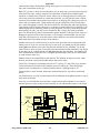
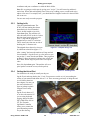
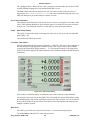
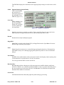
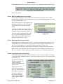
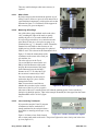
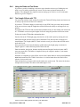
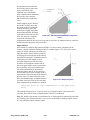
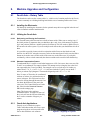
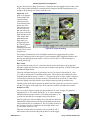
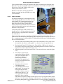
Next we put tool #2 in the spindle and enter 2 in the T DRO1. Now the tool will not be touching
the stock – it is after all 1.9" shorter than tool #1. Figure 6.18 shows that the Z program
coordinate is, as expected, 1.9".
Executing G00 Z0.0 will move the Z-axis 1.9" down and, of course, put tool #2 in contact
with the surface of the stock.
Finally it should be clear that jogging the Z-axis up so that there is room to put tool #3 in the
spindle, selecting it in the T DRO and executing G00 Z0.0 again will put tool #3 in contact
with the top of the stock.
The Tool Diameter is only used for the probe diameter for tool #99 and by the Control Software
when it is implementing cutter radius compensation with G42 and G43. Generally this function
is implemented within CAD/CAM software so the diameter information in the table is merely a
reminder of the nature of the tool you should have loaded.
Remember that we did not mind where we measured the lengths of each tool from. It could be
the spindle nose but it could be any point provided it is the same for each tool. The techniques
below use an imaginary measuring point that makes the Master Tool have zero length.
You may find that you need to follow one of the setting procedures below to fully understand
the theory. Choose the one that best matches the tooling you have.
6.4.3
Master Tool and Numbering Tools
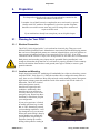
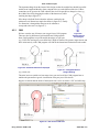
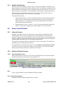
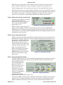
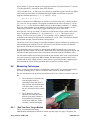
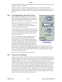
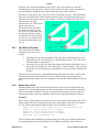
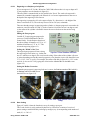
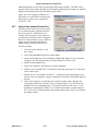
You should choose one tool from you library to be the Master Tool. Ideally it should be a tool
that you are very unlikely to ever take out of its
tool holder. Try to avoid a tool that you are likely
to break or will suffer a lot of wear. A four-flute
end-mill is easier to gauge from that a two-flute
end-cutting mill. If you have plenty of tool
holders then it is ideal to use a non-cutting tool
like the finder shown in figure 6.11 as master
tool. If you choose your master tool as the
longest of any tool you are likely to use and
measure the tools in such a way that its length
seems to be 0.0 then you will be protected from a
risk of crashing a tool into the work if you
inadvertently turn tool length offsets off. This
may seem odd and all other tools will have
negative length offsets but remember it does not
matter where the lengths are measured from –
only their relative lengths is important.
Load up the commonly used tools into their
holders and number them. The master tool, if
used for cutting, is conventionally 1 and others
are numbered sequentially. It is often convenient
that their position in a rack denotes their number.
If your master tool is never used for cutting then
call it Tool #0
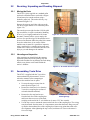
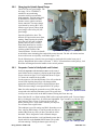
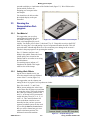
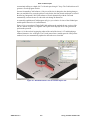
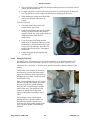
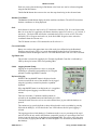
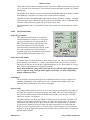
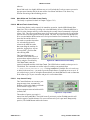
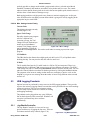
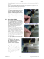
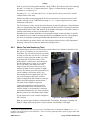
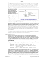
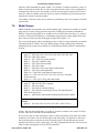
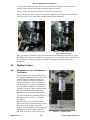
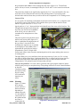
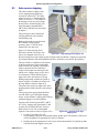
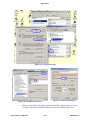
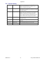
Figure 6.19 – Measuring a TTS end-mill
Draw up a grid on paper with four columns headed: Tool number, Description, Diameter and
Relative Length. Above the grid leave a space marked. Actual Master Tool length.
1
As an aside, we might actually have to jog up to get it in and then, before we change the T DRO, do G00 Z0.0
to put the Z-axis back in place it was with tool #1 – but it is as well to ignore this unless you are trying to follow this
sequence on a machine.
30635 Rev C3-1
6-9
Using Tormach PCNC 1100