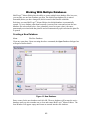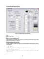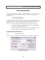
1
SHELF LOGIC® MASTER EDITION Version 14.3 USER’S MANUAL January 2005 1997- 2007 Shelf Logic Software Products. Shelf Logic® is a registered trademark of Shelf Logic Software Products All rights reserved. Phone (845) 796-4242 • Fax (845) 796-4777 1 Table of Contents TABLE OF CONTENTS ............................................................................................................. 2 TABLE OF GRAPHICS .............................................................................................................. 7 SECTION 1 – INTRODUCTION.......................................................................................... 9 WELCOME TO SHELF LOGIC MASTER EDITION ................................................................... 9 GETTING HELP ....................................................................................................................... 9 About This User Manual................................................................................................... 9 Online Help..................................................................................................................... 10 Training........................................................................................................................... 10 Technical Support ........................................................................................................... 11 What Does Technical Support Cover?............................................................................ 11 Image Support................................................................................................................. 12 Shelf Logic® Web Site User Section................................................................................ 12 System Requirements ...................................................................................................... 12 SECTION 2 – INSTALLATION......................................................................................... 13 INSTALLING SHELF LOGIC® MASTER EDITION ..................................................................... 13 Instructions for First Time Installations ......................................................................... 13 Shelf Logic Trial Version ................................................................................................ 14 Registering Shelf Logic® ................................................................................................. 15 UPGRADING FROM A PREVIOUS VERSION ............................................................................ 16 MOVING SHELF LOGIC® MASTER EDITION .......................................................................... 16 Reinstalling Shelf Logic® Master Edition....................................................................... 16 SECTION 3 - GETTING STARTED.................................................................................. 17 Starting Shelf Logic® Master Edition ............................................................................. 17 OVERVIEW ........................................................................................................................... 18 Capabilities ..................................................................................................................... 18 Plan Scaling .................................................................................................................... 18 SCREEN ELEMENTS .............................................................................................................. 19 Main Window .................................................................................................................. 19 Button Bar....................................................................................................................... 20 Tool Bar .......................................................................................................................... 22 RULERS ................................................................................................................................ 23 HOW TO EXECUTE COMMANDS ............................................................................................ 24 Menus.............................................................................................................................. 24 Hot Buttons ..................................................................................................................... 24 Shortcut Menus (Right Mouse Button)............................................................................ 24 Double-Clicking an Object ............................................................................................. 25 Drag and Drop................................................................................................................ 25 Keyboard Shortcuts......................................................................................................... 25 LIST OF MENUS & COMMANDS ............................................................................................ 27 File Menu ........................................................................................................................ 27 2 Edit Menu........................................................................................................................ 27 View Menu ...................................................................................................................... 28 Shelf Menu ...................................................................................................................... 28 Item Menu ....................................................................................................................... 28 Tools Menu...................................................................................................................... 29 Sales Menu ...................................................................................................................... 29 Report Menu.................................................................................................................... 29 Help Menu....................................................................................................................... 30 SECTION 4 – DATABASE SETUP.................................................................................... 31 CREATING THE DATABASE ................................................................................................... 31 ENTERING ITEMS INTO THE DATABASE ................................................................................ 32 Item Maintenance Form.................................................................................................. 32 Item Maintenance Field Chart........................................................................................ 33 Tips for Creating an Effective Database ........................................................................ 37 PUTTING PHOTOS INTO YOUR PLAN ..................................................................................... 38 Image File Formats......................................................................................................... 38 Transparency .................................................................................................................. 39 Three-Sided Image Support ............................................................................................ 39 SIGNAGE .............................................................................................................................. 40 MAINTAINING THE ITEMS DATABASE .................................................................................. 41 Editing the Item Maintenance Form ............................................................................... 41 Saving Changes to the Items Database........................................................................... 41 Deleting an Item From the Database.............................................................................. 41 Update From Database................................................................................................... 42 CUSTOMIZING YOUR DATABASE ......................................................................................... 43 The Default Items Database............................................................................................ 43 Changing Field Labels.................................................................................................... 44 User Defined Fields ........................................................................................................ 44 WORKING WITH MULTIPLE DATABASES ............................................................................. 45 Creating a New Database............................................................................................... 45 Opening an Existing Database ....................................................................................... 46 SHARING FILES ON A NETWORK........................................................................................... 47 Setting the Default Database .......................................................................................... 47 USING THE ITEMS DATABASE .............................................................................................. 48 The Item Selection Window............................................................................................. 48 Filtering the Database .................................................................................................... 49 Include Feature............................................................................................................... 51 Loading and Saving Filters............................................................................................. 51 Searching the Items Database ........................................................................................ 51 SECTION 5 – CREATING A DISPLAY............................................................................ 53 DISPLAY CONCEPTS ............................................................................................................. 53 Shelf/Peg Display Setup.................................................................................................. 54 Pallet Rack Display Setup............................................................................................... 57 Horizontal Slat Wall Display Setup ................................................................................ 59 Vertical Slide Display Setup ........................................................................................... 61 3 WORKING WITH SHELVES .................................................................................................... 63 Adding Shelves to a Display ........................................................................................... 63 Adding a Floating Shelf to Pegboard or Slat Wall ......................................................... 66 Locking Shelves............................................................................................................... 67 Show Shelf Numbers ....................................................................................................... 67 Moving to the Next/Previous Shelf.................................................................................. 67 Moving Shelves ............................................................................................................... 68 WORKING WITH ITEMS ........................................................................................................ 76 The Items Selection Window ........................................................................................... 76 Display-By Fields............................................................................................................ 76 Photo Images .................................................................................................................. 76 Adding Items to the Planogram ...................................................................................... 77 Placing Items on Shelves ................................................................................................ 77 Placing Items on Hooks .................................................................................................. 78 Duplicating Items............................................................................................................ 79 Flipping and Turning Items ............................................................................................ 80 Nesting Items................................................................................................................... 84 Moving to the Next/Previous Item................................................................................... 84 Grouping Items ............................................................................................................... 85 Stacking Multiple Items in a Single Facing .................................................................... 88 SECTION 6 – AUTOMATIC FEATURES........................................................................ 89 AUTOMATIC PLACEMENT FEATURES ................................................................................... 89 Next Available Location.................................................................................................. 89 Smart Shelf ...................................................................................................................... 89 Auto Center ..................................................................................................................... 91 Auto Stack Fill................................................................................................................. 91 RAPID ITEM PLACEMENT ..................................................................................................... 92 Part 1. Adding Items to the RIP Queue........................................................................... 92 Part 2. Placing Items from the RIP Queue ..................................................................... 94 Changing Items in the RIP Queue ................................................................................ 102 SMART PLAN FOR SHELVES................................................................................................ 104 Smart Plan Setup........................................................................................................... 104 Creating a Shelf Display with Smart Plan.................................................................... 105 Smart Plan Carry-Over................................................................................................. 106 SMART PLAN FOR PEGBOARD ............................................................................................ 107 Smart Plan Setup........................................................................................................... 107 Creating a Pegboard Display with Smart Plan ............................................................ 108 Smart Plan Carry-Over................................................................................................. 109 SECTION 7 – EDITING FEATURES.............................................................................. 110 Editing Display Setup ................................................................................................... 110 Editing a Shelf............................................................................................................... 110 Deleting Items and Shelves ........................................................................................... 110 SECTION 8 – OTHER FEATURES................................................................................. 111 ALIGNMENT FEATURES ...................................................................................................... 111 4 Using Guidelines to Position Items............................................................................... 111 Displaying Guidelines................................................................................................... 111 Snap To Feature............................................................................................................ 111 Grid Setup ..................................................................................................................... 112 Turning the Grid On and Off ........................................................................................ 113 The Nudge Command.................................................................................................... 113 The Alignment Commands ............................................................................................ 114 CUT/COPY/PASTE .............................................................................................................. 115 Undo Feature ................................................................................................................ 116 Redo .............................................................................................................................. 116 Plan Information........................................................................................................... 117 Version Information ...................................................................................................... 117 VIEWING FEATURES ........................................................................................................... 118 Customizing the Screen Display ................................................................................... 118 Preferences ................................................................................................................... 119 Scale, Zoom and Scrolling Features............................................................................. 123 Notes ............................................................................................................................. 125 Key Numbering ............................................................................................................. 127 SECTION 9 – FILE MANAGEMENT ............................................................................. 129 SAVING PLANS ................................................................................................................... 129 Name and Save a New Plan .......................................................................................... 129 Opening an Existing Plan ............................................................................................. 130 Saving a Copy With a New Name ................................................................................. 131 Closing a Plan............................................................................................................... 131 Deleting a Plan ............................................................................................................. 131 Exiting Shelf Logic Master Edition............................................................................ 131 PERFORMING BACKUPS ...................................................................................................... 133 Automatic File Backup.................................................................................................. 134 SECTION 10 – PRINTING................................................................................................ 135 TYPES OF PRINTOUTS ......................................................................................................... 135 PRINT OPTIONS .................................................................................................................. 135 Printer Setup ................................................................................................................. 135 Page Setup .................................................................................................................... 136 Print Planogram ........................................................................................................... 136 Advanced Printing Options........................................................................................... 138 Print Peg Holes............................................................................................................. 140 PRINTING THE PLANOGRAM AS A GRAPHIC IMAGE ............................................................ 140 Printing the Planogram to a PRN File ......................................................................... 141 Printing the Planogram to an Adobe Acrobat PDF File.............................................. 142 SECTION 11 – REPORTS................................................................................................. 143 GENERATING AND PRINTING REPORTS............................................................................... 143 STANDARD REPORTS.......................................................................................................... 144 Schematic Listing .......................................................................................................... 144 Product Listing.............................................................................................................. 144 5 Space Analysis Report................................................................................................... 144 Financial Report ........................................................................................................... 144 Item File Detail ............................................................................................................. 144 Item File Summary........................................................................................................ 145 CREATING CUSTOM REPORTS ............................................................................................ 145 Export the Plan File to Excel........................................................................................ 145 Custom Report Writer ................................................................................................... 145 SECTION 12 – SALES ANALYSIS REPORTS.............................................................. 146 SALES ANALYSIS SETUP .................................................................................................... 146 Creating the Sales Quantity File................................................................................... 146 Displaying the Sales Analysis Planograms................................................................... 147 Printing the Sales Analysis Planogram ........................................................................ 149 Printing Sales Analysis Reports.................................................................................... 149 SECTION 13 – EXPORTING & IMPORTING .............................................................. 150 EXPORTING AND IMPORTING FILES .................................................................................... 150 EXPORTING AND IMPORTING A DATABASE ........................................................................ 151 Exporting the Item File from Shelf Logic® to Excel ..................................................... 151 Creating the Items Database in Excel .......................................................................... 151 Database Fields Chart.................................................................................................. 152 Importing the .CSV File into Shelf Logic® .................................................................... 154 Database Import Checklist ........................................................................................... 155 EXPORTING PLANS ............................................................................................................. 155 Exporting the plan file to Excel .................................................................................... 155 6 Table of Graphics FIGURE 1. THE REGISTRATION DIALOG BOX ........................................................................... 14 FIGURE 2. THE MAIN SCREEN .................................................................................................. 19 FIGURE 3 ITEM MAINTENANCE ............................................................................................... 32 FIGURE 4. FRONT VIEW FIGURE 5. SIDE VIEW FIGURE 6. TOP VIEW .................................... 39 FIGURE 7. DELETED UPC CODE ............................................................................................... 42 FIGURE 8. CHANGED ITEM DIMENSIONS .................................................................................. 42 FIGURE 9. FIELD LABELS ......................................................................................................... 44 FIGURE 10. NEW DATABASE .................................................................................................... 45 FIGURE 11. EXISTING DATABASE ............................................................................................. 46 FIGURE 12. ITEM SELECTION WINDOW .................................................................................... 48 FIGURE 13. DATABASE FILTER FORM ...................................................................................... 49 FIGURE 14. DATABASE SEARCH FORM..................................................................................... 52 FIGURE 15. DISPLAY SETUP SHELF/PEG................................................................................... 54 FIGURE 16. DISPLAY SETUP PALLET RACK .............................................................................. 57 FIGURE 17. DISPLAY SETUP SLAT WALL ................................................................................. 59 FIGURE 18. DISPLAY SETUP VERTICAL SLIDE .......................................................................... 61 FIGURE 19. ADD SHELF ............................................................................................................ 63 FIGURE 20. FLOATING SHELF SETUP ........................................................................................ 66 FIGURE 21. THREE FLOATING SHELVES WITH 1 BASE SHELF.................................................... 66 FIGURE 22. BEFORE MOVING A SHELF – SMART SHELF OFF .................................................... 69 FIGURE 23. MOVING THE SHELF UPWARDS – SMART SHELF OFF ............................................ 69 FIGURE 24. MOVING THE SHELF UP MORE – SMART SHELF OFF ............................................. 70 FIGURE 25. BEFORE MOVING A SHELF U[WARDS – SMART SHELF ON .................................... 71 FIGURE 26. AFTER THE SHELF MOVE – SMART SHELF ON ....................................................... 71 FIGURE 27. BEFORE MOVING A SHELF DOWN – SMART SHELF OFF ........................................ 72 FIGURE 28. MOVING THE SHELF DOWNWARDS – SMART SHELF OFF....................................... 72 FIGURE 29.THE SHELF IS MOVED DOWN MORE - SMART SHELF OFF ...................................... 73 FIGURE 30. BEFORE MOVING A SHELF – SMART SHELF ON ..................................................... 74 FIGURE 31. AFTER MOVING A SHELF – SMART SHELF ON ....................................................... 74 FIGURE 32. PEG ITEM ON HOOK AND SAME PEG ITEM ON SHELF ............................................... 78 FIGURE 33. NESTED BASKETS .................................................................................................. 84 FIGURE 34. DRAWING THE LASSO ............................................................................................ 86 FIGURE 35. THE GROUP FORMED BY THE ABOVE LASSO ......................................................... 86 FIGURE 36. DRAGGING SHELVES WITH SMART SHELF ON (LEFT) AND OFF (RIGHT) ................ 90 FIGURE 37. STACK NUMBER .................................................................................................... 91 FIGURE 38. SMART PLAN FOR SHELVES SETUP ...................................................................... 104 FIGURE 39. SMART PLAN FOR PEGBOARD SETUP ................................................................... 107 FIGURE 40. SNAP TO .............................................................................................................. 111 FIGURE 41. GRID SETUP ......................................................................................................... 112 FIGURE 42. FIND ITEM ........................................................................................................... 117 FIGURE 43. PREFERENCES OPTIONS SCREEN .......................................................................... 119 FIGURE 44. PREFERENCES DATABASE SCREEN ...................................................................... 121 FIGURE 45. PREFERENCES PRINTING SCREEN......................................................................... 122 7 FIGURE 46. VIEWING SCALE .................................................................................................. 123 FIGURE 48. A NOTE ............................................................................................................... 125 FIGURE 49. THE NOTES DIALOG BOX .................................................................................... 126 FIGURE 50. SAVE PLAN .......................................................................................................... 129 FIGURE 51. FILE OPEN DIALOG BOX ...................................................................................... 130 FIGURE 52. PRINT PLANOGRAM OPTIONS SSCREEN ............................................................... 136 FIGURE 53. SECTION HEADERS & FOOTERS ........................................................................... 139 FIGURE 54. CREATE IMAGE FILE ............................................................................................ 140 FIGURE 55. REPORT DIALOGUE BOX...................................................................................... 143 FIGURE 56. SALES SETUP ....................................................................................................... 146 FIGURE 57. SALES ANALYSIS PLANOGRAM............................................................................ 148 FIGURE 58. COLOR CHART ..................................................................................................... 153 8 Section 1 – Introduction Welcome to Shelf Logic Master Edition Shelf Logic Master Edition is a simple to use yet powerful program specifically designed to create planograms for shelving, pegboard and slat wall merchandising displays. Using the Smart Plan features, even the most complex planograms can be created in minutes by selecting your products and letting Shelf Logic® arrange them. Other automatic features such as Smart Shelf and Next Location make item placement as simple as clicking your mouse. Your planograms can be created and printed using actual photographic images or line art representations that are scaled to the same dimensions of width, height and depth as the actual products. Statistical data is provided for the construction of the display, and for doing sophisticated space and sales analysis. Shelf Logic® Master Edition has several features that make it easy to incorporate your planograms into web pages, catalogues, documents and email. You can also share your planograms with customers and staff even if they don’t have Shelf Logic® Master Edition installed. Getting Help About This User Manual This manual provides detailed information on all of the features of Shelf Logic Master Edition, as well as tips for creating and maintaining your database, image files, and merchandising display plans. Like the program itself, this manual will keep growing and evolving in response to the needs of our users. Updates will be available for download from the Shelf Logic® web site user section. We welcome your comments on corrections or improvements that will help make this manual more useful. Please email to: [email protected] This manual assumes that you have a basic working knowledge of Microsoft Windows®. If you are not familiar with Windows® terms such as dialogue boxes, mouse-clicks, menus, Windows Explorer, etc., consider reading Microsoft’s guide entitled “Getting Started with Microsoft Windows®“ or another suitable tutorial. A basic working knowledge of Windows® and its features is essential to effective use of any software program. 9 This manual assumes that you are using a standard right-handed mouse with the left button set as the primary button. When the manual refers to clicking and double clicking, it is always with the left mouse button, unless otherwise specified. If you are left-handed, you can switch the left and right mouse buttons through the Windows® Control Panel. Throughout this manual you will see the following icon in the left margin to call attention to important procedures: Text that appears bold and italicized indicates a computer command that must be typed exactly as shown (but in normal type). When referring to a specific key on the keyboard, the name of the key will appear in brackets, for example <enter> means press the enter key. A keyboard combination such as <Ctrl + S> means you hold down the Ctrl key while pressing the letter S, (or whichever letter applies to the specific command). Instructions for executing menu commands are shown as menu name/command name: File/Save As – first click on File Menu then select the Save As command. Online Help The Shelf Logic® Help file incorporates the latest features of a Windows Help System. Online Help can be accessed from inside Shelf Logic® Master Edition by clicking on the Help Menu. The online Help System provides step-by-step "How To" instructions, and in some cases refers the user to the appropriate section of the User Manual for more detailed information. If your operating system does not support the most current Help File System, contact Technical Support for assistance. Training A four-hour telephone-based training course consisting of three sessions is available for an additional fee. To purchase and schedule training, contact the main office at: Phone (845) 796-4242 Reading through the manual prior to your training session, will significantly enhance your learning experience. The time spent learning Shelf Logic Master Edition will pay off many times over in greater productivity, better quality planogram and increased sales. 10 Technical Support Normal operating hours for the Technical Support Department are as follows: Monday – Friday 9:00 AM - 4:00 PM, EST Phone (845) 796-4242 Your purchase of Shelf Logic® Master Edition includes lifetime free email support and 6 months free telephone support. All questions regarding the operation of Shelf Logic® software should be sent to: [email protected] Response time is usually within one business day. When contacting technical support you must include the following information. Failure to provide the necessary information will result in a delayed response. • • • • • • • • Company name and User ID number. User name and phone number. Shelf Logic® product and version number. Operating system and version number. Computer processor speed and amount of RAM. Detailed description of the problem that occurred including any error message. How many times the problem has occurred. What other programs (if any) were running when the problem occurred. What Does Technical Support Cover? The role of technical support is to assist the user with operating problems, provide clarification of printed or online documentation, answer common questions about getting started, and for gathering user feedback on their Shelf Logic® experience. Technical Support is not offered as an alternative to reading the User Manual or to provide extensive training. The many features of Shelf Logic Master Edition have been designed to make the job of planogramming simple and enjoyable. However, no matter how easy a software program might be, you can only use it to its fullest capability if you learn to use it properly. With Shelf Logic Master Edition, the learning process takes the intermediate computer user about four hours. Reading our User Manual with the program running is usually all it takes. If you do not take the time to do so, you will miss out on many of the time saving features and helpful tips we provide throughout this manual. 11 Image Support The User Manual contains suggestions for preparing your images for use with Shelf Logic® Master Edition. Due to the vast number of graphic software programs currently in use, we cannot provide assistance with editing or converting your images. Please consult technical support for the graphic program you use. We can provide assistance in creating your images on a fee for service basis. Contact the Sales Department for additional details. Shelf Logic® Web Site User Section You will need a User ID and password to gain access to the web site User Section. Your User ID and password can be found in the introduction letter that is shipped with your software. If you do not have your User ID and password, please contact Technical Support. Some of the features of this section are: • • • • • Software Registration User Manual updates for download. Program updates for download. Shelf Logic® Reader Software for download. Tips and FAQ’s (frequently asked questions). System Requirements • • • • • PC compatible Windows 98, ME, NT, 2000, XP Pentium III Processor (or equivalent), 700 Mhz 96 MB of RAM (higher recommended) 16 MB Graphics Card 20 MB available hard disk space 12 Section 2 – Installation Installing Shelf Logic® Master Edition Instructions for First Time Installations (See upgrading section below if you currently run Shelf Logic® Express, Shelf Logic® Pro, or an earlier version of Shelf Logic® Master Edition.) 1. Download your Shelf Logic program from our website: www.shelflogic.com. 2. On the website, logon to the user section with your user name and password. You will see a link to download Shelf Logic Master Edition. When asked, save the file to disk. DO NOT open the file. 3. After downloading Shelf Logif Master Edition, you will have a file called ShelfLogic_ME14_Install.exe. Double-click on this file to start the installation. 4. Follow the installation instructions. The installation program will install Shelf Logic® Master Edition into a folder named “C:\Program Files\Shelf Logic Master Edition”. • A subfolder named Backup will be created for storing backup files. • A subfolder named DataFile will be created for planogram and database files. • A subfolder named Images will be created for storing photo image files. • A subfolder named Reader will be created for storing zipped reader files and one subfolder: Temp - for storing temporary files needed for creating zipped Reader files. This folder will automatically be emptied the next time a new Reader file is created. • A subfolder named Samples, which contains a practice database and demo plan files. 13 • A Shelf Logic® Master Edition Program Group will be created on the Windows® Start Menu with icons for starting Shelf Logic, moving Shelf Logic® and complete Uninstall. • A desktop shortcut for Shelf Logic® Master Edition will also be created. Shelf Logic Trial Version When Shelf Logic is first installed, it automatically becomes a trial version. It needs to be registered in order to become a fully working copy. If the program is not registered, you will see this screen when the program starts: Figure 1. The Registration Dialog Box • If you are using Shelf Logic as a trial version, then click on the “Continue with Trial” button. • If you purchased Shelf Logic and wish to register it, then click on the “Register Program” button. See the next section for information on registering your program. • If you haven’t purchased Shelf Logic and wish to do so. Click on the “Purchase Software” button and you will be taken to our website so that you can purchase the product. • You can click on the “Cancel” button to exit the program. 14 Registering Shelf Logic® After installing the program (but before running it for the first time) you will need to register your Shelf Logic® software and obtain a program key code. You can register on our website or over the phone by calling our office. To start the registration, click on the “Register Program” button. You will then be presented with a registration number. This registration number is turned into a program unlock key by calling our offices to get a program key, or by going to our web site and registering it online. The URL is: http://www.shelflogic.com/register.htm Keep the register dialog box open while you get the program key. If it is closed, you will get a different registration number each time you open the registration dialog box. Once you get the program key, enter it into the program key field and click on the “Register Program” button. The program will then be registered and fully functional. This only needs to be done once. The key code you will be issued is only valid for one installation so you will need to obtain a new key code for each copy of Shelf Logic® Master Edition that you purchase. If you need assistance in registering your software, please contact Technical Support. Note: Please refer to the section on Removing Shelf Logic® which contains important information about moving, reinstalling, and re-registering your Shelf Logic® software. 15 Upgrading From a Previous Version If you are currently using Shelf Logic® you must contact Tech Support for assistance with your upgrade and conversion to Shelf Logic® Master Edition. Moving Shelf Logic® Master Edition Please follow these instructions carefully in case you need to move Shelf Logic® Master Edition to a different computer or reinstall at a later date: 1. Copy the DataFile folder, Images folder, and Reader folder to a removable medium (floppy disk, zip disk, tape or network drive) before running the remove program. You will need to transfer these files to the new installation. 2. From the Windows Start Menu, select Shelf Logic® Master Edition/Move. 3. Shelf Logic® Master Edition will be removed from you computer and a removal code will be displayed on your screen. 4. **You must write down this removal code and store it in a safe place or send it directly to [email protected]. ** Note: You must have the removal code when you reinstall and reregister Shelf Logic® Master Edition. This removal code is valid for only one reinstall so you must have a new removal code each time the software is moved. Reinstalling Shelf Logic® Master Edition 1. Reinstall Shelf Logic® Master Edition following the instructions at the beginning of this section. 2. Copy your data files to C:\Program Files\Shelf Logic Master Edition\DataFile. 3. Copy your image files to C:\Program Files\Shelf Logic Master Edition \Images. 4. Copy your zipped Reader files to C:\Program Files\Shelf Logic Master Edition \Reader. 5. Run Shelf Logic® Register according to the instructions above. You will need both the removal code and the new registration number when contacting Technical Support. 16 Section 3 - Getting Started Starting Shelf Logic® Master Edition Once installation is complete, you may begin using and learning Shelf Logic® Master Edition. From the Windows Start Menu, select Programs, then the Shelf Logic® Master Edition Program Group. Click the Shelf Logic® Master Edition icon to run the program, or double-click the Shelf Logic® Master Edition desktop icon. A practice database and plan files have been included for use during the learning process. To access the practice files: 1. 2. 3. 4. Click File/Open Double-click the “C:\Program Files\Shelf Logic Master Edition\” folder. Double-click the Samples folder. Double-click one of the practice files. This will open a practice planogram and activate the practice database. Note: The practice database will continue to be active until you close Shelf Logic® Master Edition or activate another database. When you are ready to begin entering items into the database, make sure that item.mdb is the active database file. If you are not sure how to do this, close Shelf Logic® Master Edition and reopen it again. 17 Overview Capabilities Number of items per database file: Unlimited Maximum faces on a plan: 1000 Maximum Items stacked behind each other in a facing: Maximum shelves on a plan: 255 250 Maximum plan width: 50 Feet Maximum plan height: 50 Feet Maximum number of databases: Unlimited Maximum number of databases per plan: 1 Maximum Levels of Undo and Redo: 10 Plan Scaling Zoom Ratio: 1.5:1 to 63:1 (at 640x480 monitor resolution) Scale Ratio: 5 1/4-feet/screen inch to 1 1/2-inches/screen inch Viewing capacity: 45 x 27 feet to 3/4 x 1/14 feet (at 640x480 monitor resolution) Item measurement accuracy to 1/16 inch 18 Screen Elements Main Window If you are running Shelf Logic® Master Edition while reading this manual, you will need to open a planogram to activate all of the menus and features. Figure 2. The Main Screen 1. Menu Bar 2. Button Bar 3. Plan Window 5. Rulers 6. Tool Bar 7. Status Bar 8. Scroll Bars 19 4. Item Selection Window 1. Menu Bar – Contains all of the commands and features of Shelf Logic® Master Edition. 2. Button Bar – Shortcuts to some of the most frequently used commands. 3. Plan Window – This is where you will construct and edit your plan. 4. Item Selection Window – Displays your Items database. 5. Rulers – Located above and to the left of the Plan Window to aid in the positioning of items and shelves. One inch on the ruler bar equals one foot of actual display. 6. Tool Bar – Contains several useful tools for viewing, creating and editing your plan. 7. Status Bar – Displays information about the selected item or shelf. When a shelf is selected (highlighted) the Status Bar will display the shelf dimensions. When an item is selected (highlighted) the Status Bar will display the item details. 8. Scroll Bars – Used to scroll through the Plan or Items Windows when the display is too large to be viewed in one screen. Button Bar New - Opens a new planogram. If another planogram is currently open, an alert box will remind you to save it. Open - Opens an existing planogram file. Save - Saves the current planogram. Print – Opens the Print Dialogue Box. Find - Finds items on the current planogram that match the selected item. Cut - Cuts (removes) the selected item, shelf or group from the planogram. Copy - Copies the selected item, shelf or group from the planogram. Paste - Pastes a cut or copied object at the upper left corner of the Planogram Window. Undo - Reverses the last action taken. Redo - Restores the last Undo action. Add Shelf - Opens the "Add Shelf" dialogue box. Add Items – Positions the Items Window next to the Plan Window. Items – Opens Item Maintenance. 20 Duplicate Right – Duplicates the selected item to the right. Duplicate Up – Duplicates the selected item up. Flip – Flips the selected item to one of 3 sides. Zoom –Enlarge or decrease the view of the planogram. Snap – Opens the Snap-To setup dialogue box. Stack – Opens the Stack Setup dialogue box. Hook – Changes the peg hook size for an item on the planogram. Help - Opens the Help System. 21 Tool Bar 1 2 3 4 5 6 7 8 1. Arrow – Toggles between the normal arrow pointer and the zoom pointers. 2. +Magnify – (Zoom In) Turns the pointer into a magnifying glass to enlarge the view of a specific item, shelf or section of the plan (changes the display only, not the actual plan). Each mouse click enlarges the view by one increment. 3. –Magnify – (Zoom Out) Turns the pointer into a magnifying glass to shrink the view and display more of the plan (changes the display only, not the actual plan). Each mouse click shrinks the view by one increment. 4. Grabber Tool – Turns the pointer into a hand and moves the plan up/down or right/left within the Plan Window (an alternative to Scroll Bars). 5. Scale Slider – Re-scales the size of the view in the Plan Window (an alternative method for zooming in and out). 6. Smart Shelf – Turns the Smart Shelf automatic features on and off. 7. Next Loc – Turns the automatic placement feature on and off. 8. Hook Size – Displays the default peg hook length. Detailed information about all of the above features can be found later in this manual. 22 Rulers Shelf Logic has rulers that can be made visible or hidden. The ruler can start measuring from the top of the display downwards or be set to measure from the bottom of the display upwards. In addition, the ruler’s starting point can be changed to start at any location. This is very useful for measuring the distance between objects. By default, the ruler start measuring from the top left of the display. This can be changed in the Display Setup Dialog Box. There you will find a checkbox that indicates the ruler will start measuring from the bottom of the display upwards. Changing the Rulers Starting Point The ruler’s starting point is changed by clicking in the box between the rulers and dragging the starting point around until the desired position is found. When you let go of the mouse, the rulers will change to reflect the new ruler starting points. Figure 3. Changing the Ruler Starting Point Resetting the Rulers Starting Point You can reset the rulers starting point to the upper left by double-clicking on the gray box between the rulers. Hiding Rulers You can toggle the display of the ruler form the View Menu. There is a selection called “Show Ruler”. Selecting this turns the ruler display on and off. 23 How to Execute Commands The many features of Shelf Logic® Master Edition can be executed by using menus, keyboard shortcuts, button and tool bars, mouse clicks, or drag and drop. Before executing some commands, you must first select a shelf or item on which the command will be performed. Clicking the left mouse button on a shelf or item selects and highlights it in bright red. Menus There are two ways to execute commands from the menus: 1. Using the mouse, click the menu name then click the command on the drop-down menu. 2. Using the keyboard, hold down <Alt> and press the underlined letter in the menu name, then press the underlined letter in the command name. Hot Buttons The Hot Buttons located on the Button Bar are shortcuts to some of the more frequently used features. All of the Hot Button commands can also be found in the menus. Shortcut Menus (Right Mouse Button) In addition to the main menus, there are several shortcut menus that can be accessed by clicking the right mouse button over an object. These menus are object-sensitive, which means that the available options will be different depending upon the object you right-click on. We suggest experimenting with the right mouse button feature as much as possible. Once familiar with the different menus, you will find them to be considerable step-savers. • • • • Right clicking over a shelf will select the shelf and open a Shortcut Menu of commands relating to shelf arrangement. Right clicking over the plan area will open a Shortcut Menu of commands relating to display setup. Right clicking over an item in the Item Selection Window will select it and open a Shortcut Menu of commands relating to item maintenance. Right clicking over an item in the Plan Window selects it and opens a Shortcut Menu relating to item placement in the plan. 24 Double-Clicking an Object Double-clicking an object in the plan window, such as a shelf or item, opens a maintenance menu that allows you to change the shelf dimensions or update the item in the database. Double-clicking the plan area opens the Display Setup dialogue box. Double-clicking an item in the Item Selection Window places the item on the plan. Drag and Drop Items can be dragged from the Item Selection Window and dropped onto the plan. To drag an item, select it from the Item Selection Window and hold down the left mouse button as you move the mouse. Release the mouse button to place the item on the plan. When dragging and dropping an item, the Smart Shelf feature and Snap-To features still apply if turned on, but Next Available Location has no effect. Keyboard Shortcuts Some frequently used commands can be executed directly from the keyboard by holding down <Ctrl> or <Alt> and pressing a corresponding letter. If a particular command has a Keyboard Shortcut, it will appear on the menu next to the command name as follows: <Ctrl + letter>. 25 Reference List of Keyboard Shortcuts Add Items to Database Add Items to RIP Queue Item Maintenance File/Save Open Existing Plan Show Guidelines/Turn off Guidelines Show Peg Holes/Turn Off Peg Holes Show Photos/Turn Off Photos Show By Quantity Sold Display Setup Undo Redo Cut Copy Paste Find (Items on Planogram) Zoom In Zoom Out Grabber Tool Print Planogram Scroll Forward through Item Maintenance Scroll Backward through Item Maintenance Exit Shelf Logic® Copy Selected Area <Ctrl +I> <Ctrl + A> <Ctrl + M> <Ctrl + S> <Ctrl + O> <Ctrl + G> <Ctrl + H> <Ctrl + T> <Ctrl + Q> <Ctrl + D> <Ctrl + Z> <Ctrl + R> <Ctrl + X> <Ctrl + C> <Ctrl + V> <Ctrl + F> F8 F7 <Shift> + Drag Mouse <Ctrl + P> <Alt + D> <Alt + B> <Alt + F4> <Ctrl + Drag> 26 List of Menus & Commands File Menu New – Opens a new plan. Open – Opens an existing plan. Close – Closes a plan and clears the Plan Window. Delete – Permanently deletes a plan from your hard drive. Save – Saves the current plan. Save As – Saves a copy of the current plan in a new file with a new name. Send Plan File – Compresses the plan file and related data into a single file for use with the Shelflogic Reader software. Save Plan as Image – Exports the plan to an image file. New Database – Creates a new database file for items. Open Database – Closes the current items database and opens another one. Unit of Measure − Toggles between English and Metric unit of measure. Import – Imports data into the items database from other applications. Export Item File – Export the items database for use with other applications. Export Plan – Exports the plan data for use in other applications. Page Setup – Set page margins for planogram printouts. Printer Setup – Change printers and printer options, such as paper orientation. Exit – Closes Shelf Logic® Master Edition. Edit Menu Undo – Reverses up to 10 operations. Redo – Reverses the last Undo operation. Delete – Removes one or more items or shelves from a plan. Cut – Deletes an object and stores it in the clipboard for reuse. Copy – Copies an object to the clipboard for reuse. Paste – Places the clipboard contents in a new location. Find – Finds and highlights matching items in a plan. Copy Image to Clipboard – Copies the selected area of the plan to the Windows clipboard for pasting into another application. Enter Note – This will let you enter a ‘post-it’ style note. 27 View Menu Show Grid – Turns Grid display on and off. Show Ruler – Turns Ruler display on and off. Show Button Bar– Turns Button Bar display on and off. Show Tool Bar – Turns Tool Bar display on and off. Show Guidelines – Turns display of guidelines on and off. Show Pegholes – Turns display of pegholes on and off. Show Shelf Numbers – Turns display of shelf number tags on and off. Show Photos – Turns photo image display on and off. Show Notes – Turns the display of notes on and off. Display Setup – Changes the plan configuration. Grid Setup – Changes the type and number of grid lines. Snap To Setup – Turn the Snap-to features on and off. Scale – Changes the scale of the plan on the screen. Zoom in – Enlarges the view of a section of the plan. Zoom out – Shrinks the view to display more of the plan. Preferences – Set defaults for some of the program features. Change Field Labels – Rename optional database fields. Info – Displays information about the current plan. Shelf Menu Add – Set shelf dimensions and adds one or more shelves to the plan. Change – Changes shelf dimensions or placement of an existing shelf. Lock Shelves – Prevents shelves from being moved with selected items. Item Menu Maintenance – Add items or change existing items in the Items database file. Place – Adds items onto the RIP Queue. Change Hook Length – Edit peg hook length for an item already on the planogram. Number in Stack – Define the number of items to be placed in a stack. Flip – Rotate or turns item(s). Duplicate Up – Duplicates the highlighted item upwards. Duplicate Right - Duplicates the highlighted item to the right. Align – This leads to another menu which lets you align selected item left, right, top or bottom. Filter – Specify which items are displayed in the Items Window. Filter Off – Turns off the current filter and displays the entire database in the Items Window. Bring to Front – This brings the selected item(s) to the foreground. Bring to Back – This brings the selected item(s) to the background. Next Item – Move the selection to the next item on the plan. Previous Item – Move the selection to the previous item on the plan. Update from Database – Updates item details that have been modified since the plan was created. 28 Tools Menu Arrow – Toggles between the normal arrow pointer and the Tool Bar pointers. Magnify Up – (Zoom In) Turns the pointer into a magnifying glass to enlarge the view of an item, shelf or section of the plan (changes the display only, not the actual plan). Each mouse click enlarges the view by one increment. Magnify Down – (Zoom Out) Turns the pointer into a magnifying glass to shrink the view and display more of the plan (changes the display only, not the actual plan). Each mouse click shrinks the view by one increment. Grab – Turns the pointer into a hand and moves the plan up/down or right/left within the Plan Window (an alternative to Scroll Bars). Smart Shelf – Turns the Smart Shelf automatic features on and off. Next Available Location – Turns the automatic placement feature on and off. Item Key Numbering – Turns manual key numbering mode on and off. Smart Plan for Shelves – Setup Smart Plan to automatically fill shelves. Smart Plan for Pegs – Setup Smart Plan to automatically fill pegboard. Smart Plan Carry-Over – List of selected items that Smart Plan could not fit on the display. Sales Menu Show by Qty Sold – Colors the planogram by quantity sold and sales ranking level. Show by Dollar Sold – Colors the planogram by dollars sold and sales ranking level. Show by Dollars Per Cubic Feet – Colors the planogram by dollars per cubic feet and sales ranking level. Show Normal Colors – Returns to normal planogram display. Sales Analysis Report Ranked by Unit Movement – prints the Sales Analysis report with items ranked by the Qty Sold field. Sales Analysis Report Ranked by Dollar Volume – prints the Sales Analysis report with items ranked by the Dollars Sold field. Sales Analysis Report Ranked by Return on Cubic Space – prints the Sales Analysis report with items ranked by the Dollars/Cu Ft field. Enter Sales Quantities – Enter quantities sold and ranking levels for items on the planogram. Report Menu Print Planogram – Set print options for planograms. Print Shelving Schematic – Set print options schematic printout. Set Section Headers & Footers – Set headers and footers for planogram printouts. Schematic Listing – Print or display information for constructing the actual shelving. Product Listing – Print of display list of items on the display, quantities and placement. Space Analysis Report – Analyzes display space usage. Financial Analysis Report – Analyzes display profitability. Item File Detail – Detailed information about the Items database file. Item File Summary – Item file listing can be used as an aid to product selection. 29 Help Menu Contents – Opens the Help system. About – Shelf Logic® version and release information. 30 Section 4 – Database Setup Creating the Database Shelf Logic Master Edition requires a minimal amount of initial setup, however, as with any new software, setup should be given careful consideration. Instructions for creating a database must be carefully followed. Data entry and product dimensions must be accurate. The quality of your final planogram is dependent upon an accurate, well-planned database. There are 3 ways to get product information into the database. 1. Manually enter the data using the Item Maintenance Screen. 2. Import the data from an Excel spreadsheet using the Shelf Logic Import feature 3. Put the data directly into the Access 2000 database. This is done outside of Shelf Logic and is for users who have a familiarity of writing queries or programs in Access 2000 Which method you choose will depend upon the size of your database, whether your database already exists in another application, and your experience level with database concepts. In this section, items will be entered into the database through Shelf Logic® Master Edition. Importing a database is covered in Section 14. Note: Be sure that all plan files are closed and that only the main Shelf Logic® Master Edition application window is open (gray background). Many of the Hot Buttons and Menus will be inactive, however, the items database can still be accessed. If you previously had the sample files open during this working session, close Shelf Logic® Master Edition and reopen it to access the default items database. Metric Planograms Menu: Menu: File/Unit of Measurement/English File/Unit of Measurement/metric Shelf Logic supports both English and Metric systems. You can switch between the two of them, even while you are working on your plan. When in English, measurements are in inches, except for the display size, which is measured in feet. When in metric, all measurements are in centimeters (cm). To switch between English and metric, use the “File/Unit of Measurement” menu selection and choose English or metric. 31 Entering Items into the Database Item Maintenance Form Hot Button: Items Menu: Keyboard Shortcut: Items Maintenance <Ctrl + I> When you execute one of the above commands, the Item Maintenance form will open as shown below. The name and location of the active database file will appear on the title bar of the form—double check that you are using the correct database. Figure 3 Item Maintenance Each line in the form is called a field: • use <Tab> to move forward one field, • use <Shift +Tab> to move backward one field, • or click the mouse inside the field to select it. The UPC Code is the key field of the database and should always be entered first. If an item has already been entered using this UPC Code, the item details will fill the Item Maintenance form. The UPC Code must be unique for each item—duplicates are not allowed. 32 Some fields are required entries and some fields require data in a specific format. Each field has a maximum allowable number of characters. If a field is user-defined, that means numbers or letters are acceptable. Refer to the Item Maintenance chart below. While your database is still in the planning stage, we suggest creating a practice planogram and printing out a sample of each report so you can see the effects of any empty or userdefined fields. The following chart details the type of data to be entered when creating your database in Shelf Logic® Master Edition: Item Maintenance Field Chart Field Name (**Can Edit Field Label) **UPC Code **SKU Code Data Type REQUIR Max ED Chars Text Yes 25 Text No 25 Text No 25 Text No 25 Text Yes 1 Text No 50 Text No 50 **Item No. **Vendor No. Item Type **Ven Name **Item Name Description The industry standard Universal Product Code. This field is the primary (key) field, which Shelf Logic® Master Edition uses to organize and locate items. It must be a unique number for each item—no duplicates are allowed. The manufacturer's identification code for the particular item. Although this is an optional field, leaving it empty may have significant impact on your final results. Code or number to identify the vendor that supplies this item. A Shelf Item is an object that can only be placed on a shelf. A Peg Item can be placed on a shelf or hung from a hook. A Sign is a photo that can be placed anywhere. The full name of the vendor that supplies this item. Although this is an optional field, leaving it empty may have significant impact on your final results. 33 Field Name (**Can Edit Field Label) **Desc **Category DATA REQUIR ED Max Chars Text No 50 50 Text No Number Yes TYPE Width 12 Height 12 Number Yes Number Yes Number No Number No Number No Depth Weight Ctn Pack 12 Nest Amount 12 4 12 Sugg Retail 12 Currency No Currency No Cost 12 Last Chg Dt 8 Text No 34 Description A detailed description of the item. This field can be used to organize items by groups of related products for database filtering. Some reports are sorted by category. The width of the item (left to right) in inches. Enter whole numbers or decimals (1, 1.25, 1.5). Do not enter fractions. The height of the item (top to bottom) in inches. Enter whole numbers or decimals (1, 1.25, 1.5). Do not enter fractions. The depth of the item (front to back) in inches. Enter whole numbers or decimals (1, 1.25, 1.5). Do not enter fractions. The weight of a single item in ounces. The quantity of items packed into a single shipping carton. The height in inches of the portion that shows when this item is stacked one inside the other. Enter the suggested retail price of the item in dollars. This field is used to calculate profit margins. Do not enter dollar signs. Enter the wholesale price of the item. This field is used to calculate profit margins. Do not enter dollar signs. No entry is made by the user. This field is controlled by Shelf Logic® and will automatically display the date of the last change to this item. Field Name (**Can Edit Field Label) Peg Hole From Left Data Type 10 Number Peg Hole From Top **User 1 **User 2 **User 3 Image File Transparent Color REQUIR Max ED Chars Yes (for peg items) 10 Number Yes (for peg items) Text Text Text No No No Text No Number No 50 50 50 100 12 Description This field is only available when the Peg Item Type is selected. Enter the distance from the left edge of the package to the center of the peg hole. Enter whole numbers or decimals (i.e. 0.25, 0.5, 0.75, 1). Do not enter fractions. This field is only available when the Peg Item Type is selected. Enter the distance from the top edge of the package to the center of the peg hole. Enter whole numbers or decimals (i.e. 0.25, 0.5, 0.75, 1). Do not enter fractions. Optional, user defined field. Optional, user defined field. Optional, user defined field. Enter the path (location) and filename of the image file to be associated with this item. Clicking the browse button will allow you to select the file from the contents of your computer. Check desired transparent background color or click on the button to enter your own color. Record Counter – Located at the upper right corner of the Item Maintenance form, the first number indicates the current record number and the second number indicates the total number of records in the database. Forward & Back Buttons – Used to scroll through the contents of the Items Database. This is an alternative to searching when you have a small database, and an alternative to the “Save” button to edit a record and continue scrolling. Save Button - Once the required data has been entered, click the Save button (or use the keyboard shortcut of <Alt + S>). After clicking the Save Button, the Item Maintenance form will clear so that another item can be entered. 35 Cancel Button– Clears the screen without saving changes. Delete – Deletes the current record from the Items Database. Exit –Closes the Item Maintenance screen and returns to the main Shelf LogicMaster Edition screen. Item Colors - Click the Item Color Button to select a color scheme and pattern that will print in line art printouts and display on screen when photo images are turned off. Each item can have its own outline color, fill color, and pattern. If no color scheme is selected, a default of white with black outline will be used. Start Find & Find Next –Searches the Items Database for specific items. Grid View- when selected, shows the full database in a spreadsheet format from the within the item maintenance window . Include -This check box is used to include an item in a database filter when the item does not meet the criteria of the current filter. It should be left deselected (no check) during setup. 36 Tips for Creating an Effective Database It is important to put some thought and planning into the initial setup of your database in order to achieve the best possible results. Following are some points to consider during the setup phase. 1. Enter a few test items and create some practice planograms. 2. Print out the practice planogram and a sample of each report on the Report Menu. 3. If you have left any fields empty, note the effect on reports, the Item Selection Window, the Plan Window, and planogram printouts. 4. When entering your item dimensions, use the side most likely to face the front of the shelf. Although you can use the Flip Item feature to change the facing on your planogram, the dimensions entered into the database should be the ones most often used. 5. We suggest color-coding items by category. This method helps organize your planogram and produces an attractive line art printout. 6. When you start Shelf Logic® Master Edition, the default database will automatically open. You can create as many databases as you like using different file names; however, you can only use one database per plan. If you do create other databases, always make sure you know which one is currently active. 7. Some changes to the Shelf Logic® database can have detrimental effects on existing plans. Never move or rename a database after it has been used to create any plans. Items deleted from the database will also be deleted from existing plans. 8. Do you need more than one database? There are several features in Shelf Logic Master Edition that make it easy to work with a large database, and in most cases will eliminate the need to have more than one. There is no limit on the number of items in a Master Edition database; however, the maximum number of items in an Excel database is 65,536. 9. Should you create your database in Shelf Logic Master Edition or Excel? If you are starting from scratch and your database is small, entering items directly into the Item Maintenance form is a simple process. If your database is large, using Excel is more efficient. If your database already exists in another database program, you will need to use Excel to prepare the database for import into Shelf Logic Master Edition. You should be an intermediate level Excel user and be familiar with basic database concepts before attempting to import a database. 10. Although the .mdb database file can be edited in Access, we strongly recommend this be avoided. Never open the file in Access in design mode. 37 Putting Photos into your Plan In order to use photographic images in your planograms, all you have to do is enter the item’s image file name and location in the Items database. Once entered, you should not move or rename image files and folders or you may have to recreate these links. Image files can be stored on any drive and in any folder, however, we recommend storing them in the Images subfolder created during installation of Shelf Logic® Master Edition. Image File Formats Shelf Logic® Master Edition supports the following image file formats: .BMP .CGM .JPG, .JPEG .FAX .FPX .GIF .IMG .MAC .MSP .PCD .PCT .PCX .PNG .PSD .RAS .SCT .TGA .TIF .WMF .WPG Bitmaps Computer Graphics Metafile Jpegs Generic Fax Kodak FlashPix Graphics Interchange Format Gem Image Mac Paint Microsoft Paint Kodak Photo CD MacPict File PC Paintbrush Portable Network Graphics Photoshop File Sun Raster File Scitex Continuous Tone Targa Tagged Image Format File Windows Metafile Format WordPerfect Graphics Format Transparency is supported for all image formats with your choice of any transparent color. In addition, each item can have its own transparent color. Note: Some compressed image formats, like jpegs, don’t make good candidates for having a transparent background. This is because the transparent color in the image may get changed slightly when compressed and will no longer match the specified transparent color you defined for that item. If you are going to use photographic images with your plans, we suggest that you have access to a graphics software program that can perform the following functions: • Convert files between various formats. 38 • • • Resize or resample color images – Shelf Logic Master Edition will automatically scale the bitmap image to the proper size for the planogram, however, if the image is too large or too small, print quality may be affected. The recommended size is approximately 100 to 400 pixels height or width, with the second dimension proportionate to the first. Cropping – the photograph should be taken straight on and never at an angle. Crop as close as possible to the edges of the actual item, removing as much excess background as possible. Change background color – since the printed planogram background is white, the graphic image background should also be white. If you want transparency, then color the background a unique color not found anywhere else in the image. Transparency Shelf Logic supports transparent images for all image types. Each item can have its own transparent color. This is done by specifying a transparent color on the item maintenance screen. You can select “none” for no transparency, “Black” to make black the transparent color, “white” to make white the transparent color, or click on the “Choose Transparent Color” button to select a different transparent color. Note: Transparency doesn’t work well with compressed image types such as a jpeg. This is because the transparent color may change when the image is compressed and no longer match the color you selected. Three-Sided Image Support Shelf Logic® Master Edition supports industry standard 3-sided images. These images have a file extension of .1 .2 or .3. Only the image named .1 is entered into the image file field but all three images must be in the same folder. When the Flip Item feature is used, Shelf Logic® Master Edition will automatically use the item image with the corresponding side number. When an item is flipped to side 2, imagefile.2 will be used; and when flipped to side 3, imagefile.3 will be used. Figure 4. Front View Figure 5. Side View 39 Figure 6. Top View Signage Shelf Logic lets you create signs and certain types of fixtures you can use on your plans. Signs are items with an item type of “I”. They have width and height, but no depth, weight, nesting amount, suggested retail, peg hole from top and left. You can assign a photo image to a sign and put the sign anywhere on your display. The sign is on the plan but not included in the Space Analysis or Financial Analysis reports. Creating a sign is similar to adding an item to the database. The difference is that the item type is “I” for a sign item. Create a UPC Code, or make one up, for the item and enter it. Then enter the other information you need. You will need to enter the signs height and width, and you should specify the photo of this sign. Otherwise the sign will appear as a colored box. Sign will appear in the item list box with an item type of “I” and will come before the peg and shelf items in the item selection list box. Select the sign item as you would any other item. Then place the sign in exactly the location you wish. You can drag the sign as you would any item. A sign can be deleted by selecting it and pressing the Delete Key, the same as deleting an item. Fixture Signs You can create signs that simulate fixtures. For example, you could create a sign in the shape of a barrel and give it a barrel photo. This barrel can then be put onto the place and items can be put behind the barrel, making it seem like the barrel is a display for holding items. 40 Maintaining the Items Database Editing the Item Maintenance Form Menu: Hot Button: Item/Maintenance Items Executing one of the above commands will open an empty Item Maintenance screen to enter a new item or edit an existing one. Locate the item you wish to edit using one of the following methods: • • • • Select the item on the planogram, right-click and select Edit Item. Double-click the item on the planogram. Locate the item in the Items Window, right-click and select Edit Item. Open Item Maintenance and search the database for the item. Saving Changes to the Items Database After making changes to an existing item click the Save button to save the changes and clear the Item Maintenance form; or, click the right or left scroll button to save the new record and proceed to the next record. Once an existing item has been edited, Shelf Logic® Master Edition will automatically insert the current date in the Last Change Date field. Editing the item’s UPC code will create a duplicate item with a new UPC code. The original item will remain unchanged. Deleting an Item From the Database After locating the item in the database, click the Delete button. Deleting an item in this manner permanently erases the item from the database. 41 Update From Database Menu: Item/Update from database When a plan file is opened, Shelf Logic® Master Edition automatically checks the database for possible changes in three areas: 1. Does the item on the plan still exist in the current database? • If the item has been deleted, a warning dialogue box will open listing the deleted UPC codes and deleted items on the plan will be marked with a large black X as shown below. This item cannot be updated and should be removed from the plan. Figure 7. Deleted UPC Code 2. Are the length, width and depth of the items on the plan the same as in the current database? • If not, the item is marked with a large black exclamation point as shown below. 3. Are the peg hole locations (left and top) the same as in the current database? • If not, the item is marked with a large black exclamation point as shown below. Figure 8. Changed Item Dimensions The Update from Database command can be executed by selecting the above menu command, or by right-clicking the item on the plan. The selected item will be updated to reflect the new information in the database. The item's position may then need to be adjusted manually. 42 Customizing Your Database The following database features can be customized, making the Shelf Logic® Master Edition database extremely flexible: Set the default database to a Shelf Logic® database in any folder on any drive. Change any optional field label so that any data can be entered and labeled correctly. • Three user-defined fields that can be used for any additional data you wish to include in the database. • • The Default Items Database View Menu: Preferences The default database is the database that automatically opens when you start Shelf Logic® Master Edition. The default is preset to C:\Program Files\Shelf Logic Master Edition\datafile\item.mdb, but you can create more database files and make any one of them the default. This feature is particularly useful if you wish to store your database file on a shared network drive. Note: You must close and restart Shelf Logic® for the new default database to take effect. When you open an existing plan, the database used to create that plan will also open and become the new default for the current work session. If you are not sure which database is currently active, click the Items button on the button bar and check the window’s title bar. Upon exiting Shelf Logic® Master Edition, the default database reverts back to the default specified in Preferences. 43 Changing Field Labels View Menu: Change Field Labels Field labels can be customized for all optional fields and can be up to 9 characters long. If you have more than one database, changes to field labels effect all of them. Note: Although you can change the UPC Code field, it is not an option field and entry of a unique number is required. Use caution when changing the UPC Code field label. Figure 9. Field Labels User Defined Fields In addition to changing field labels, fields 9, 10 and 11 are user defined fields and can be used for any data the user wishes to include in the database. These features make the database extremely flexible. User fields are not used in any of the Shelf Logic® standard reports but can be used in custom reports. 44 ® Working With Multiple Databases Shelf Logic Master Edition has the ability to create multiple item database files, however, you can only use one Item Database per plan. The default item database file is named Item.mdb (unless you have changed it) and is located in the DataFile subfolder. Each time you start Shelf Logic® Master Edition, the default database is automatically opened. To use a database other than Item.mdb, you must first create and activate the new database file as described below. Once a database is used to create a plan, it becomes permanently associated with that plan file and will automatically open each time the plan file is opened. Creating a New Database Menu: File/New Database Close any open plans. Upon executing the above command, the Open Database dialogue box will open as shown below: Figure 10. New Database Enter a name for the new database and click OK. The new database will become the active database until you select another one or close and restart Shelf Logic® Master Edition. The Item Window will appear empty until items are entered into the new database. 45 Opening an Existing Database Menu: File/Open Database Close any open plans. Upon executing the above command, the Open Database dialogue box will open as shown below. Select a database file and click the Open Button. You can then create a new plan using the new items database. Figure 11. Existing Database 46 Sharing Files on a Network If you are planning to store Shelf Logic® data files on a networked drive you must first install a licensed copy of Shelf Logic® on each user’s workstation. Database and plan files can then be stored on a networked drive and accessed simultaneously from multiple workstations. If a user is editing an item in Item Maintenance, all subsequent users will be locked out of that record until the edit has been completed and saved. Multiple users can also access a single plan file but only the first user can save changes to that plan. All subsequent users will have a “read only” copy. Setting the Default Database The default database is preset to C:\Program Files\Shelf Logic Master Edition\Datafile\Item.mdb and should be moved to the network drive using Windows Explorer; or create a new database to be set as the default. To Create a New Database: 1. Open Shelf Logic® Master Edition 2. Select File Menu/New Database 3. Name the database file and save it on the network drive From Each Workstation: 1. Select View Menu/Preferences 2. Click the Browse Button 3. Select the new default database 4. Click OK Note: you must close and restart Shelf Logic® Master Edition for the new default to take effect. 47 Using the Items Database The Item Selection Window When a new plan is created or an existing plan opened, the Item Selection Window will appear to the right of the Plan Window and display the active database. The Item Selection Window is automatically sized and positioned to fit within the main Shelf Logic window. Both the Plan Window and the Item Selection Window can be resized by dragging the window’s edge. Place the mouse pointer over the right edge of the Plan Window and the left edge of the Items Window. When the pointer becomes a double-headed arrow, drag to resize both windows for a perfect fit. Figure 12. Item Selection Window Items are listed in the Items Window in order of Item Type. Signage items are listed first and are preceded by the letter “I”; Peg items are listed next and are preceded by the letter “P”; shelf items follow and are preceded by the letter “S”. The Item Number is the default display field, however, you can easily change the display field to UPC Code, SKU Code, Item Name or Description. To change the default Item display field: 1. Place the mouse pointer inside the Items Window and right-click. 2. Select the desired display field from the menu. When you change the display-by field, your selection becomes the new default and will remain in effect until the next time you change it. The display-by field can also be set in Preferences. The selected display-by field will print on line art planograms. 48 To locate an item in the Item Window, click the mouse inside the window and type the first letter or number of the item. The curser (highlighted bar) will jump to the beginning of that section; or use the scroll bars to scroll through the list. When working with a large database the Filter Feature (see below) can be used to restrict the items that appear in the Item Selection Window for easier selection. Once an item has been added to a planogram, the text color for that item will turn red, indicating that the item has already been selected. Removing that item from the planogram will restore the text color to black. Filtering the Database Menu: Item/Filter Item/Filter Off Executing the above Filter command will open the Create Filter dialogue box as shown below: Figure 13. Database Filter Form Filtering allows the user to select which items are displayed in the Items Window and in Item Maintenance. Filters can be turned on, off or changed at any time during a working session. To filter the database, you enter matching criteria in any field or fields of the filter form. An "equal to" search is performed, which means that only items that are an exact match to the criteria entered will be included in the Item Window. You can increase the flexibility of filtering by using Boolean operators such as “greater than” and “less than”. Another way to expand a filter is by using the Include feature in Item Maintenance. 49 To create a filter: • • • Click the Item Menu and select Filter. Fill in the data to be matched in one or more fields. Click the Filter Button. To remove the filter and display the entire database: • Click the Item Menu and select Filter Off. Examples of Boolean Operators: ABC* *ABC *ABC* >=123 =>123 <=123 =<123 <>123 =123 >123 <123 Starts with ABC Ends with ABC Contains ABC Greater than or equal to 123 Greater than or equal to 123 Less than or equal to 123 Less than or equal to 123 Not equal to 123 Equal to 123 Greater than 123 Less than 123 If two (or more) fields in the filter form contain data, only those items that match both fields will be displayed in the filtered database. Examples of Filters: • • • • • Selecting Peg Items in the Items Type field will display only peg items in the Items Window. Selecting Shelf Items, will display only shelf items. An entry in the Category field of the filter form will display only the items that have the exact same entry in the Items Database Category field. An entry of <123400000000 in the UPC Code field will display items with UPC’s from 1 through 123399999999. An entry of >5.00 in the Suggested Retail field will display only those items with a suggested retail of over $5.00. An entry of Item Type = Peg Item, Category = Toys, and Suggested Retail <2.00 will display only peg items from the toy category with a suggested retail of $1.99 or less. 50 Include Feature This feature is used to display items when they do not meet the current filter criteria. To activate the Include feature: • • • • • Turn off any existing filter. Click the Items Button on the Button Bar. Search the database for the items you want to include. Click the Include box at the lower right corner of the Item Maintenance form. Create a filter as described above. Loading and Saving Filters Once you have defined a filter, it can be saved and used at a later time. Click on the “Save Filter” button. You will be presented with the Windows Save Dialog Box, where you can navigate to the desired folder and saved. All saved filters have a file extension of “FLR”. To load a filter, click the “Load Filter” button and enter the name of the saved filter. That filter will now be in effect. Auto Filters If you save a filter and give it the same name as the plan, then when the plan is opened up, that filter will automatically be in effect. For example, we have a plan called “Beverages”. We open the Beverages plan and create a filter and save that filter, giving it the name “Beverages”. The next time the Beverages plan is opened, the beverages filter will be used to filter the database. This lets you use a large database and use filters to limit the database to a more easily handled size. Searching the Items Database Hot Button: Menu: Items Items/Maintenance There are several ways to locate an item in the database. The method you use will depend upon the situation and personal preference. Upon executing the above command, the Item Maintenance screen will open. Method #1: The forward and back arrows located just below the record counter will scroll through the database one record at a time. Method #2: Enter the UPC code and press <tab>. The item details will appear on the Item Maintenance screen. 51 Method #3: Right-click an item in the Items Selection window or on an open plan. Method #4: Click the Start Find button to open a search screen as shown below: Figure 14. Database Search Form The search parameters may be a word, several words, a number, or even just the first few characters or digits of any field. This is a "begins with" search, which means that a search parameter of "St" entered into the Vendor Name field will match any vendor name that begins with St. Case is ignored so that ST, St, and st, are all the same. Enter search parameters in any field and click the Start Find button. The Item Maintenance Screen will open with the first match found. To continue the search, click the Find Next button until the message "No match found" is displayed. To begin a new search, click the Start Find button again and repeat the above procedure. 52 Section 5 – Creating a Display Display Concepts This chapter will introduce the basic concepts of creating a planogram. Additional features of Shelf Logic Master Edition are covered in Sections 6, 7 and 8. The steps for creating a planogram are really very simple: 1. Define the display type and dimensions. 2. Add shelves to the display. 3. Add items to the display. Your items are represented on the planogram by a scaled line art box, a custom shape, or a photographic image. Items can be placed anywhere on the planogram, however, warning messages will alert you when an item is not properly positioned, or if there is not enough space. Automatic placement features such as Smart Shelf, Next Available Location, and Smart Plan make it easy to position or move items and shelves around the planogram. You can save various planogram scenarios and create reports to analyze the financial and market possibilities of each arrangement. There are three display types in Shelf Logic Master Edition: 1. Shelf/Peg is used to create a shelving planogram, a pegboard planogram, a combination shelf/pegboard planogram, or pallet rack planogram. 2. Slat wall is used to create a horizontal slat wall planogram. 3. Vertical Slide is used to create a planogram where items are displayed on vertical fixtures such as waterfall hooks or literature racks. Once the Display Setup is complete, the new planogram will appear in the Plan Window. The default Items Database will open in the Items Selection Window. If you wish to use a different database, you must create and open that database before adding items to the planogram. The database used to create the planogram will be permanently associated with the plan file so that each time you open the plan, the associated database will open with it. 53 Shelf/Peg Display Setup Hot Button: Menu: New Plan File/New After executing one of the above commands, the Display Setup dialogue box will open as shown below. A typical gondola display setup is shown: Figure 15. Display Setup Shelf/Peg Type Select Shelf to create a shelving display, Shelf/Peg for a pegboard display, or a combination shelf and pegboard display. Display Length & Display Height These dimensions will determine the total area of your display. Measurements can be entered in feet, feet and inches, or all inches. 54 Vertical Distance & Horizontal Distance Between Peg Holes These measurements determine the type of pegboard used for the display background. A minimum of .5” must be entered. Standard pegboard is one inch vertical by one inch horizontal. If you prefer not to have a pegboard background, you can turn off the peg holes later from the View Menu. Upright Thickness Vertical uprights are the framework onto which shelves are attached. For standard wall shelving or gondola shelving you may leave the thickness at zero. For heavy-duty pallet racks, the thickness of the uprights can impact available shelf space and must be accounted for within the total display size (see Pallet Rack Setup below). Upright Color Clicking on the “Change Color” button lets you specify a color for the uprights on your plan. This opens up the standard Select Color Window where you can choose any color. Vertical Spacing Between Notches This is the vertical distance between the slots on the vertical uprights into which the shelves will be attached. One inch is standard for most gondola or wall shelving. With one-inch slot positions, shelf height and shelf movement must be in one-inch increments. With two-inch slot positions, shelf height and shelf movement must be in two-inch increments. Kickplate This is the height of the kickplate or base unit. The kickplate appears as a solid black area at the bottom of the display. The top of the kickplate is the lowest possible position where a shelf may be placed, but it is not an actual shelf and cannot hold items. Peg Hook Size Enter the default peg hook size for the display. Show Grid & Show Ruler These features are used for item positioning and alignment. They can be turned on and off from Display Setup or from the View Menu. We suggest leaving the ruler on and the grid off for most displays. Section Spacing These measurements will determine how many sections your display will have and the length of each section. You can create up to 15 variable-sized sections per display. Enter the length of each section in inches. If your display has only one section, enter the total length in Section 1. Note: The total length of all the sections must equal the total display length. 55 Measure from Bottom Up If you check this, the ruler will start at the bottom of the display and measure upwards from there. The ruler’s zero point starts above the kickplate. This feature can be turned on and off while working on the plan, so you can switch the zero point from the top to the bottom of the display as needed. The ruler’s zero point can also be changed by clicking on the bow between the rulers and dragging the vertical and horizontal zero point anywhere on the screen. Display Color Select a background color for the display. This color is for on-screen viewing only and does not affect printed planograms. The printed planogram will have a white background to accommodate photographic images. OK Button Accepts the current setup, closes the Display Setup box, and opens the display in the Plan Window. Cancel Button Closes the Display Setup box without creating a new display or saving changes to an existing display. Set Default Clicking the Default button will save the current display setup. Each new planogram will begin with these dimensions, however, they can be changed as needed. Each time you click the Default button, the current setup will overwrite the previous one saved, but will not affect any planograms created previously. Your basic display should now be visible in the Plan Window. Drag the Scale Slider Button on the Tool Bar to scale the view to your preference. When learning the program, it’s usually easier to position items and shelves in a larger scale. 56 Pallet Rack Display Setup Figure 16. Display Setup Pallet Rack Type Select Shelf/Peg to create a pallet rack display. Upright Thickness A pallet rack display is created the same as a shelf/peg display with the exception of the upright thickness. Vertical uprights are the framework onto which shelves are attached. For standard wall shelving or gondola shelving you may leave the thickness at zero since shelves attach at the back of the display. For heavy-duty pallet racks, the thickness of the uprights can impact available shelf space and must be accounted for. When the upright thickness is set to a number greater than zero, the combined measurement of the uprights must be subtracted from the section lengths. Failure to do so will cause the following warning message: “The display width is too small to fit the sections that were entered.” 57 Example: • • • • • • Display length = 8 feet Thickness of Vertical Uprights = 4 inches Number of sections in the display = 1 Total number of uprights = 2 Combined measurement of the 2 uprights = 8 inches Section spacing must be 88 inches. Note: The total length of all sections, plus total upright thickness must equal the total display length. You are now ready to add shelves to a shelf/peg or pallet rack display. For pegboard displays, you are ready to add items and/or floating shelves. 58 Horizontal Slat Wall Display Setup Figure 17. Display Setup Slat Wall Type Select Horizontal Slat wall. Display Length & Display Height These dimensions will determine the total area of your display. Measurements can be entered in feet, in feet and inches, or all inches. Vertical Distance Between Slats Measure the distance from the top of the channel to the bottom of the slat. Standard slat wall has a vertical distance of 3 inches. Upright Thickness Use the default setting of 0. Vertical Spacing Between Notches Use the default setting of 1. 59 Kickplate This is an optional setting for slat wall that can be set to 0 if no base is needed. Peg Hook Size Enter the default peg hook size for the display. Show Grid & Show Ruler These features are used to aid with item positioning and alignment. They can be turned on and off from Display Setup or from the View Menu. We suggest leaving the ruler on and the grid off for most displays. Section Spacing If your slat wall display has only one section, enter the total length of the display in Section 1. The total length of all the sections, less space for uprights where applicable, should equal the total display length. Display Color Select a background color for the display. This color is for on-screen viewing only and does not affect printed planograms. The printed planogram will have a white background to accommodate photographic images. OK Button Accepts the current setup, closes the Display Setup box, and opens the display in the Plan Window. Cancel Button Closes the Display Setup box without creating a new display or saving changes to an existing display. Set Default Clicking the Default button will save the current display setup. Each new planogram will begin with these dimensions; however, they can be changed as needed. Each time you click the Default button, the current setup will overwrite the previous one saved, but will not affect any planograms created previously. Your slat wall display should now be visible in the Plan Window. Drag the Slider Button on the Tool Bar to scale the view to your preference. You are now ready to add shelves, floating shelves or items to the slat wall display. 60 Vertical Slide Display Setup Figure 18. Display Setup Vertical Slide Type Select Vertical Slide. Display Length & Display Height These dimensions will determine the total area of your display. Measurements can be entered in feet, in feet and inches, or all inches. Horizontal Distance Between Slats Measure the distance from the left edge of the first vertical fixture to the left edge of the next vertical fixture. Upright Thickness Uprights are optional for Vertical Slide displays and can be set to zero. Vertical Spacing Between Notches This is the vertical distance between slots on the vertical uprights into which shelves or racks will be attached. 61 Kickplate This is an optional setting for Vertical Slide. Peg Hook Size Enter the default peg hook size for the display. Show Grid & Show Ruler These features are used to aid with item positioning and alignment. The can be turned on and off from Display Setup or from the View Menu. We suggest leaving the ruler on and the grid off for most displays. Section Spacing If your vertical display has only one section, enter the total length of the display in Section 1. The total length of all the sections, less space for uprights where applicable, should equal the total display length. Display Color Select a background color for the display. This color is for on-screen viewing only and does not affect printed planograms. The printed planogram will have a white background to accommodate photographic images. OK Button Accepts the current setup, closes the Display Setup box, and opens the display in the Plan Window. Cancel Button Closes the Display Setup box without creating a new display or saving changes to an existing display. Set Default Clicking the Default button will save the current display setup. Each new planogram will begin with these dimensions; however, they can be changed as needed. Each time you click the Default button, the current setup will overwrite the previous one saved, but will not affect any planograms created previously. Your vertical display should now be visible in the Plan Window. Drag the Slider Button on the Tool Bar to scale the view to your preference. You can now begin adding floating shelves or items to the display. 62 Working with Shelves Adding Shelves to a Display Hot Button: Menu: +Shelf Shelf/Add After executing one of the above commands, the Add Shelf dialogue box will open as shown below. Shelves are always added to the display from the bottom up and can be added individually or in multiples. Shelves should never be longer than the section length defined in display setup. Figure 19. Add Shelf Add __ Shelves Enter the number of shelves to be added to the active section. Section Number Defaults to the active section. The active section is the last section in which the mouse was clicked. You can change the default section number if necessary. Length This is the length of the shelf in inches from left to right. This measurement defaults to the length of the section as defined in Display Setup and cannot be changed. Note: If you need to add a shelf that is shorter or longer than the section length, the floating shelf feature should be used. Distance Between Shelves 63 This is the shelf height, or the distance from the top surface of the current shelf to the bottom surface of the shelf above it. It represents the amount of space in which you can place products. This is the area reserved for items and will appear as a shaded area on the screen. Note: The top shelf of each section will still have the specified shelf height reserved for items even though there is no shelf above it, as indicated by the shaded area. Depth The depth of the shelf in inches as measured from the front edge of the shelf to the back edge. Thickness The thickness of the shelf in inches. This measurement should be made at the thickest point of the shelf. Distance from Bottom This is a way to place the shelf in any desired position. Just specify the number of inches (or cm) and the shelf will be placed that distance from the bottom of the display, just above the kickplate. Peg Area Height Above each shelf area can be an area set aside for peg items. This field lets you specify the height of this peg area in inches (or cm). This area is always the same length as the shelf. The Peg Area goes between the shelf area and the shelf above it. If the shelf height is 12 inches and the peg area height is 6 inches, then the distance to the next shelf above is 18 inches. OK Button Accepts the shelf dimensions, closes the Add Shelf dialogue box, and adds the shelf or shelves to the display in the Plan Window. 64 Cancel Button Closes the Add Shelf dialogue box without adding shelves. Color Clicking on the “Color” button lets you choose the color of the shelf or shelves being added, or changed if you care changing an existing shelf. This display the “Color Selector” Window, which is displayed below, where you can choose a shelf fill color, outline color and pattern. Fill Color The shelf’s current fill color is displayed. The “Change Color” button will let you change this fill color. When the color is changed, you can see what the shelf color and pattern looks like in the sample to the right. Outline Color The shelf’s current outline color is displayed. The “Change Color” button will let you change this outline color. When the color is changed, you can see what the shelf color and pattern looks like in the sample to the right. Pattern You have a choice of 7 different patterns for the shelf. Click on the option button below the pattern you wish to choose. You will see this pattern in the sample picture to the right. Default Saves the current shelf dimensions as the default shelf setup. The defined shelves should now appear on the display and are colored blue. To select a specific shelf, place the mouse pointer over the shelf and click the left mouse button. The selected shelf turns red. The shaded area above the shelf is a visual aid for determining the space occupied by each shelf. Even though you will not see the pegboard background in this reserved area on your screen, you can still place peg hook items in the reserved area. When a peg item is placed with its bottom edge on a shelf, the item automatically becomes a shelf item as indicated on the Status Bar. 65 Adding a Floating Shelf to Pegboard or Slat Wall A floating shelf is attached directly to pegboard or slat wall instead of to vertical uprights, and can be used to simulate many different pegboard or slat wall accessories. Floating shelves can be used with any display type and can be dragged to any position within the display. The procedure for adding a floating shelf is identical to adding a regular shelf, except that the Section Number must be zero. A floating shelf can be any length since it does not attach to uprights. Figure 20. Floating Shelf Setup The following display uses a full-sized base shelf and 3 floating shelves. Notice how the floating shelves attach directly to the pegboard instead of the standards. Figure 21. Three Floating Shelves with 1 base shelf. 66 Locking Shelves Menu: Shelf/Lock Shelves After building your shelving display, this feature locks the shelves in place and prevents you from accidentally moving a shelf along with an item or group of items when experimenting with different arrangements. Show Shelf Numbers Menu: View/Show Shelf Numbers Selecting this option turns the display of shelf number tags on and off and is particularly useful when working with Smart Plan for Shelves. Note: If you have rearranged the shelf positions it is possible that the shelf numbers will not be in consecutive order on your planogram. Moving to the Next/Previous Shelf Menu: Keyboard: Item/Next Previous Item/Shelf < or > or , or . key You can use the “<” and “>” keys too move to the next and previous shelf. A single shelf must be selected before pressing the “<” or “>” keys. The “<” key is also the “,” (comma) key and either can be used to move the selection to the previous shelf The “>” key is also the “.” (period) key and either can be used to move the selection to the next shelf. 67 How Shelves are Placed on the Plan When first adding shelves to a section, the shelves are placed from the bottom up. The first shelf is placed so that the top of the shelf is level with the top of the kickplate, or if no kickplate, the shelf top is level with the bottom of the display, the bottom of the shelf actually hangs below the display. In a reality, the top of the kickplate if the first shelf. From the first shelf, the shelf height extends upwards and if there’s a peg area height specified, then that extends upwards after the shelf height. After that comes the second shelf. For example, the shelf height of the first shelf is 12 inches and the peg area height is 6 inches. So there’s a total of 18 inches in between the shelves. The bottom of the second shelf starts at 18 inches up, and if this second shelf thickness is an inch, then the top of the second shelf is 19 inches above the top of the first shelf. If you specify a “Distance from the bottom”, then the shelf will start at this location, regardless of shelf heights and peg area heights. Moving Shelves This is where the “logic” in Shelf Logic comes in. The shelves act in very specific ways to help you in moving them around the display, and lend themselves to trying different display scenarios. Much of this behavior is controlled by the Smart Shelf feature. When Smart Shelf is turned off, then after the shelves are moved, the shelves remain in place but their shelf height and peg area height are adjusted to fit the newly placed shelves. With Smart Shelf turned on, then after the shelves are moved, the position of the shelves above the moved shelves are moved up or down so the shelf height and peg area height remain the same. If there isn’t enough room for the changes requested, in other words, not enough room at the top to push shelves upwards, you will get an error message and the move will be undone. Some examples will make this clearer. Moving Shelves Up in the Same Section – Smart Shelf Off With Smart Shelf off, a moved shelf will stay where placed and its shelf height and peg area adjusted according to the location of the shelf above. Let’s look at an example of this. 68 Figure 22. Before Moving a Shelf – Smart Shelf Off In the figure above, we have three shelves, each with a shelf height of 12 inches and a peg area height of 6 inches. The middle shelf is selected and will be moved upwards, as shown in the next figure. Figure 23. Moving the Shelf Upwards – Smart Shelf Off The shelf has been moved upwards slightly. Since Smart Shelf is off, the moved shelf’s height and peg area are not preserved. As the shelf is moved upwards, first the peg area height is reduced and when there’s no more peg area, then the shelf height is reduced, as shown in the next figure. 69 Figure 24. Moving the Shelf Up More – Smart Shelf Off Here, the middle shelf has been moved up even more, and since there’s no more peg area, then the shelf height of the moved shelf is reduced. If there was never a peg area height specified, then only the shelf height is reduced as the shelf is moved upwards. Moving Shelves Up in the Same Section – Smart Shelf On With Smart Shelf on, a shelf stays where placed, but the shelves above this shelf are pushed upwards so the shelf height and peg area of the moved shelf remains unchanged. In other words, as the shelf is moved, the other shelves move out of its way. Let’s look at an example. 70 Figure 25. Before Moving a Shelf U[wards – Smart Shelf On Here are three shelves before the move. The middle shelf is selected and will be moved upwards. Since Smart Shelf is on, the shelf above the selected shelf will move upwards along with the selected shelf, as shown in the next figure. Figure 26. After the Shelf Move – Smart Shelf On In the figure above, you can see that the middle shelf is moved upwards and the shelf above it is also moved the same amount, so that the shelf height of the moved shelf remains at 12 inches and the peg area height of the moved shelf remains at 6 inches. 71 Moving Shelves Down in the Same Section – Smart Shelf Off When moving a shelf downwards with Smart Shelf off, then the shelef height and peg area of the moved shelf increases and the shelf height and peg area of the shelf below is reduced. Let’s look at an example. Figure 27. Before Moving a Shelf Down – Smart Shelf Off Here are three shelves before the move. The middle shelf is selected and will be moved downwards. Since Smart Shelf is off, them the shelf heights are adjusted to fit the new shelf locations. Figure 28. Moving the Shelf Downwards – Smart Shelf Off 72 As the middle shelf is moved down, its shelf height remains the same but the peg area is increased. If there’s no peg area, then the shelf height is increased. Below the moved shelf, the peg area is reduced for the shelf below. As the shelf is moved down, first the peg area is reduced, and when there’s no more peg area, then the shelf height is reduced, as shown in the figure below. Figure 29.The Shelf is Moved Down More - Smart Shelf Off In the above figure, the shelf is moved down enough so that the shelf height of the shelf below is reduced. Moving Shelves Down in the Same Section – Smart Shelf Off When Smart Shelf is on, then as shelves are moved downwards, the position of the shelves above are changed to fit the existing shelf heights and peg areas. Here’s an example: 73 Figure 30. Before Moving a Shelf – Smart Shelf On Here are three shelves, with the middle one selected for the move. When the shelf is moved down, the top shelf is also moved down, so that the shelf height and peg area height of the selected shelf remains the same. Figure 31. After Moving a Shelf – Smart Shelf On 74 The shelf height and peg area of the moved shelf remains the same as before the move. The shelf height and peg area of the shelf below are reduced. The top shelf is moved downwards the same distance as the selected shelf, keeping the shelf height and peg area height of the selected shelf constant. Overlapping Shelves You can drag a shelf past another shelf. With Smart Shelf off, the shelf heights are adjusted, with Smart Shelf on, the shelf positions are adjusted. You can insert a shelf in between two other shelves. The shelves above will move up and make room for the selected shelf and any items you might have on that shelf. Moving Shelves Left and Right You can move shelves to other sections of the plan. It is suggested that you turn Smart Shelf on when doing this so that any shelves in the way are adjust to make room for the moved shelf and items on that shelf. With Smart Shelf off, the moved shelf will have its shelf height and peg area adjusted after being moved to the new section, depending on the positions of the shelves already placed in that section. 75 Working With Items The Items Selection Window The Items Window should appear to the right of the Plan Window. If it is not visible, click the +Items Button on the Button Bar. The Items Window is automatically sized and positioned to fit within the main Shelf Logic window. Both the Plan Window and the Items Selection Window can be resized by placing the mouse pointer over the right edge of the Plan Window and the left edge of the Items Window and dragging the double-arrow mouse pointer. Items are listed in the Items Window in order of Item Type. Peg items are listed at the top and are preceded by the letter P, followed by shelf items. Display-By Fields The Item Number is the default display field, however, you can easily change the display field to UPC Code, SKU Code, Item Name or Description. To change the default Item display field: 1. Place the mouse pointer inside the Items Window and right-click. 2. Select the desired display field from the menu. Note: Unlike previous versions, the Display-By field now affects both the screen display and the planogram printout. When printing a planogram with line art and text, the Item Number field and the selected Display-By field will both appear on screen and on the printout. When you change the display-by field, your selection becomes the new default and will remain in effect until the next time you change it. The display-by field can also be set in Preferences. Photo Images View Menu: Show Photos With the Photo Image feature turned on, you can build your planograms using actual photo images. For the purpose of speed and convenience, you can switch between line art mode and photo mode at any time by clicking on the above menu option. 76 • • • If there is no image associated with a particular item, a line art box will be substituted. If an item has a custom shape associated with it, the custom shape will appear on the planogram in line art mode only. If an item has both an image and custom shape, the shape will appear in line art mode and the image will appear in photo image mode. Adding Items to the Planogram Keyboard: Mouse: <Enter> key adds the selected item to the plan Double-click the Item Drag & Drop the Item When an item is added to a plan, it represents a facing, and this facing can have multiple items stacked together, depending on the shelf depth or peg hook length. You can specify the number of items in a facing, or let Shelf Logic automatically determine the maximum number of items that will fit in a facing. There are 2 ways to add an item to the plan: 1. An item can be added by clicking on the desired item in the item listbox on the right and dragging it onto the plan to the appropriate location. 2. Another method is to double-click on the desired item in the item listbox. The item will then appear in the upper left of the display. If the “Auto Mouse” feature is turned on (this is done in Preferences), then the mouse cursor will be positioned over the item so you can easily click and drag it to the desired location. If you have the Next Location feature turned on, then double-clicking will put the item onto the selected shelf in the next available location (more on this in a later chapter). Placing Items on Shelves Both shelf item types and peg item types can be placed on shelves. If a shelf item is not properly positioned on the shelf, or does not fit in the selected position, a warning message will alert you. In manual mode these warning messages can be overridden and the item can be placed anywhere on the planogram. Use caution when overriding warnings since it is possible to place an item where no real space exists. 77 Placing Items on Hooks Hot Button: Display Setup: Menu: Hook Hook Size Item/Change Hook Length Peg items are added in the same manner as shelf items, either by dragging it from the item listbox onto the plan or by double-clicking the item. When the Next Location feature is turned off, peg items will appear at the next available shelf location. When a peg item is added to the peg area, it is assigned the default hook size but this can be changed at any time.When moving a peg item on the planogram, the item will automatically snap to the nearest available peg hole. You cannot place a peg item where there is no peg hole to accommodate the hook. Figure 32. Peg item on hook and same peg item on shelf The default hook size is set in display setup and the size is displayed in the Hook Size box located on the Toolbar. You can change the default hook size in Display Setup or on the Toolbar at any time. You can also change the hook size for any item already on the plan, or for a group of items already on the plan. 78 Duplicating Items Hot Button: Menu: Dup Right Dup Up Item/Duplicate Right Item/Duplicate Up Once you have items on the planogram, you can duplicate them using one of three methods. With a little practice, you will discover which method is best suited to each situation. The Duplicate Up Command will copy a selected item facing and stack the copy on top of the original. You can Duplicate Up repeatedly until you run out of space. The Duplicate Right command works the same way, but will place the copy to the right of the original. This is the easiest method for duplicating facings of items. 79 Flipping and Turning Items Hot Button: Menu: Flip Item/Flip An item on the planogram can be flipped onto one of three sides. Executing one of the above commands will flip the selected item to the next side. The Status Bar will display the current side number and corresponding dimensions. If 3-sided image files are used, the appropriate image will be displayed for each side. The Flip feature is useful for filling excess space at the end of a shelf. By shutting off Smart Shelf and Next Loc, you can manually add an item and flip it until it fits the available space. There are 3 sets of command that handle product flipping. There is the “Flip” command, the Turn command and the Rotate command. When you flip an item to the side, top or front, it will do so regardless of the previous angle of rotation, if any. 80 Turn an Item The “Turn” command will turn an item upside down or turn it 90 degrees clockwise or counter clockwise. The “Turn” command can be found on the “Item - Flip” submenu and is only active when one or more items are selected. You can turn the selected item or items 90 degrees clockwise or counter clockwise, upside down or rightside up. Turning an item is the same as rotating it in the Z-Axis. You can turn an item regardless of its current angle of rotation on the X-Axis or Y-Axis. The other angles don’t change, only the Z-Axis is when turning an item. When you turn an item, it will do so regardless of the previous angle of rotation, if any. When you specify a turn angle, the item is turned to this always starting at rightside up. So if you turn an item 90 degrees clockwise and then turn the item 90 degrees counter-clockwise, the item will end up turned 90 degrees counter-clockwise starting at the rightside up position. If the turn started at the previous position of 90 degrees clockwise, the item would end up back at its rightside up position. When an item is turned, its product image is also turned automatically. 81 Rotate an Item This command lets you rotate an item to any angle in 3 dimensions. The Rotate command is accessed through the Item – Flip submenu. When you select the Rotate command, you will see the following window: An item can be rotated on the X, Y and Z axis. For each, you can enter an angle from 0 to 359. The item will then be rorated to that angle. If you check the “Add to Current Angle” checkbox, then the angles specified will be added to the current angles of rotation. Below each axis is an illustration of the way the item rotates on this axis. For the X axis, the axis goes through the sides of the item. When it’s rotated, it tilts towards you, so that at 90 degrees, you are seeing the top of the item. For the Y axis, the axis goes through the top and bottom of the item. As it’s rotated, the right side of the item comes forwards and at 90 degrees, you are seeing the side of the item. For the Z axis, the axis goes through the front and back of the item. As it’s rotated, it turns clockwise. At 90 degrees, the item is turned on its side. 82 When you rotate an item, the height and width of the item are changed to reflect the way the item looks like when looking straight at it. It desn’t try to simulate a 3D effect. For example, when you increase the angle of the X axis and it tilts forwards, it has the effect of reducing the height of the item As an item is turned on the Z axis, it has the effect of increasing both the height and width of an item. So even though the image is turned and looks the same size, the bounding box that surrounds the item is larger than when the item is not turned. 83 Nesting Items Items can be stacked one inside another, such as baskets, bowls or pots. A base item is placed on the shelf and then duplicated up using the Dup Up feature. In the Nest Amount field of Item Maintenance, enter the height of the nested item that will show above the base item. This dimension is measured from the top edge of the item downward. For example, if you have a 6 inch high basket and you want the top inch of each basket to show above the base item, enter 1 in the Nest Amount field. Figure 33. Nested Baskets Moving to the Next/Previous Item Menu: Keyboard: Item/Next Previous Item/Shelf < or > or , or . key You can use the “<” and “>” keys too move to the next and previous item. An item does not have to be selected. If an item is not selected, the selection will start with the first item or last item if the “<” key is used. If an item is selected, then the selection will move to the next or previous item. The “<” key is also the “,” (comma) key and either can be used to move the selection to the previous item. The “>” key is also the “.” (period) key and either can be used to move the selection to the next item. 84 Grouping Items You can select a group of items, or items and shelves, by drawing a lasso (a dashed line) around the items. You only need to include a portion of an item in the lasso to include it in the grouping. To draw a lasso around a group: 1. Position the mouse pointer just outside one corner of the group. 2. Hold down the left mouse button and drag the mouse so that the lasso forms around each item, or a part of each item. The mouse can be dragged up, down, left, right or diagonally. 3. Release the mouse button. When the mouse button is released, all of the items in the group will be selected (red). The group can then be moved, copied or deleted. When including shelves in a grouping, at least one shelf in the group must contain an item-you cannot select empty shelves using this method. Use the Lock Shelves feature on the Shelf Menu to prevent shelves from accidentally being moved with groups of items. In addition to moving groups of items, you can also use this feature to change peg hook size or stacking numbers for a group of items on the planogram. Select the group, select Items Menu/Change Hook Length, or Items Menu/Number in Stack and make the changes for all items in the group at the same time. To de-select a group, click anywhere outside of the group. 85 Figure 34. Drawing the Lasso Figure 35. The Group Formed by the Above Lasso 86 87 Stacking Multiple Items in a Single Facing Shelf Logic lets you put multiple products in a single facing. This is accomplished simply by moving one item over another. Even if they overlap just a little, they are considered in the same facing. When multiple items are stacked together, they will share the shelf depth. For example, if you have a 12 inch deep shelf with 2 different items in a facing, each item is allotted 6 inches of depth. Selecting an Item in a Multiple Facing Clicking on a face selects the first item in that face. If you hold down the CONTROL key and click on the face again, the next item in back will be selected and so forth. If you have 4 different items in a facing, then you can select the last item by clicking on the facing, and then holding down the CONTROL key and clicking three more time. If you have selected the last item and click again, the first item in the stack is selected. Changing Item Order You can change the item order in a multiple stack by selecting an item in the stack and using the “Item – Bring to Back” or “Item – Bring to Front” menu commands to bring the item forwards and backwards through the stack. Reporting Multiple Facing On the Product Listing Report, multiple items have the same key number but a letter is placed after the item to indicate it’s part of the same facing. So if we have three different items in a multiple facing, and the key number is 3, then the items will appear on the Product Listing Report as 3A, 3B and 3C. 88 Section 6 – Automatic Features Automatic Placement Features Next Available Location The Next Available Location feature is turned on and off by clicking the Next Loc button located on the Toolbar, or by selecting it from the Tools Menu. The feature is active when the bottom of the button is red. When placing a Shelf Item, the Next Available Location feature will automatically place items in the next available space on the selected shelf. Items are placed from left to right until all available space is filled. This is the easiest way to fill available shelf space with individual items. When adding a Peg Item, the Next Available Location feature will place the item on the selected shelf as a shelf item. To add a Peg Item to the pegboard or slat wall area, this feature must be turned off. When there is not enough space to place an item on the selected shelf, a warning message will alert you. To continue adding items you must select another item, select another shelf, or shut off the Next Available Location feature and add the item manually. The item will then appear at the top left corner of the Plan Window and can be dragged to the desired location. Use the Flip Feature to fit the item in the available space (see Section 5 – Flip Feature). Smart Shelf Smart Shelf is a group of automatic features that function together. Smart Shelf is turned on and off by clicking the Smart Shelf button on the Toolbar, or by selecting it from the Tools Menu. The Smart Shelf group of automatic features is active when the bottom of the button is red. 1. Smart Shelf – checks the height, width and depth of each item added to the planogram to make sure it will fit on the selected shelf. A warning message will tell you which dimension is too large and the item will not be added. You can edit the shelf to accommodate the item or override Smart Shelf by shutting it off and adding the item manually. Exercise caution when adding items in manual mode since it is possible to place items where no real space exists. 2. Auto Place – This is an extremely useful feature that properly positions items for you. When placing items next to each other, it can be difficult to line them up properly using your mouse. Items may appear jagged and uneven. With the Auto Place feature, all you need to do is drag an item close to the desired location and release the mouse button. Auto Place will align the item against the next closest item. 89 3. Auto Move – This feature allows you to move a shelf together with any items already placed on that shelf. When Smart Shelf is turned off, the shelf will move but the items will remain in their original position. 4. Auto Align –This feature allows you to drag a shelf from one location to another, or from one section to another. Smart Shelf will properly position the shelf between the vertical uprights. 5. Auto Arrange – This feature allows you to move several shelves while still maintaining the height specified in the Add Shelf dialogue box. In the figure below, 3 shelves were added each with a height of 12”. With Smart Shelf on, shelf #2 was dragged upwards so that shelf #1 now has a height of 25”. As shelf #2 was dragged, everything above it moved with it. Shelves #2 and #3 were repositioned but still have the original 12” height. The second figure shows the effect of dragging a shelf with Smart Shelf turned off. Only shelf #2 moved—the items on it, as well as shelf #3 remained in their original place. Figure 36. Dragging Shelves with Smart Shelf On (left) and Off (right) 90 Auto Center This feature is always turned on and cannot be turned off. When adding or moving a shelf, auto center will position the shelf to the nearest available notch on the vertical uprights. When adding or moving peg items, auto center will position the item to the nearest available peg hole. This assures accuracy when building the physical display. Auto Stack Fill Hot Button: Menu: Stack Item/Number in Stack After executing the above command, the Stack Number dialogue box will open. When you add an item to a planogram, you are actually adding a facing of that item. A facing is a stack of items that fills a shelf or peg hook from the front edge to the back edge. By default, Auto Stack Fill is always on so that Shelf Logic Master Edition will place as many items as will fit on the shelf or peg hook. If the peg hook length or shelf depth is changed, the quantity in the stack will automatically recalculate. Figure 37. Stack Number Number in stack – This will override Auto Stack Fill and specify a stack number for the selected item. Auto Stack Fill – A check mark indicates that the feature is active. OK Button – Saves changes to the Stack Fill dialogue box. Cancel Button – Exits without saving the stacking information. Default Button – Makes the entered number the default Stack Fill for all new items added to the planogram. It will remain the default until a new default is selected or a new plan is opened. Each time a new planogram is started, the default will return to Auto Stack Fill. 91 Rapid Item Placement Master Edition version 14.3 introduces our new RIP (Rapid Item Placement) Technology. This lets you place items on the plan faster than ever. RIP consists of 2 parts. The first consists of adding items to an item queue, the second part is rapidly placing these items on the plan. When using RIP, the ALT key is used for the first and second parts. Part 1. Adding Items to the RIP Queue There are two methods used to add items to the Queue. Method 1. Selecting from Item Listbox. If you hold down the ALT Key and double-click on an item in the item listbox, that item will be added to the RIP Queue. You can add as many items as you want into the Queue. Method 2. Entering Item UPC Codes Manually You can enter the UPC Codes for the desired items directly into the Queue. You can view the RIP Queue by selecting “Place Item On Planogram” from the “Item” menu, or by entering CONTROL-A. This is the RIP Queue Window: 92 In the textbox next to “UPC Code”, you can enter the UPC Codes of the desired item, one on each line. After each UPC Code is entered, press the “Enter” Key to go to the next line, as shown below. When you are finished, click on the “OK” button to saves the entered items in the RIP Queue. Save Queue List You can save the list of entered UPC Codes in the RIP Queue to a text file that can be edited with notepad or similar. When you click on the “Save List” button, you will be asked for the name and location of the saved Queue. The RIP Queue file name has an extension of “.RIP”. Load Queue List You can load a saved RIP Queue into the current Queue. When you click on the “Load List” button, you will be asked for the name and location of the saved Queue. When you enter the name, the “UPC Code” textbox will be filled with the contents of the saved Queue. Clear Queue Clicking on this button will clear the current RIP Queue. You will be asked to verify before the Queue is cleared. Any items selected by ALT-double-clicking on the item listbox will appear in the RIP Queue and appear in the UPC Code textbox. 93 Part 2. Placing Items from the RIP Queue Once one or more items are in the RIP Queue, they can be placed onto the plan one at a time or in groups. Method 1. Placing Single Item from the RIP Queue You can place a single item onto your plan from the RIP Queue by holding down the ALT Key when you click on the left mouse button. When you do this, the next item in the Queue will be placed directly under the current mouse position. Each time you click the mouse when the ALT key is pressed, another item from the Queue is placed onto the plan. If you click the mouse without the ALT key pressed, it behaves as normal. After the left mouse button is pressed, you can either release it to place the item where it is or just move the mouse and the newly placed item under it to a different location. If you are placing an item in a peg area, it may move after you release the mouse button. This happens because the item needs to put its peg hole over the closest peg hook location. Method 2. Placing Mutliple Items from the RIP Queue You can place multiple items on your place by using the mouse to indicate the area to be filled with items. First you must hold down both the ALT and CONTROL Keys. Then click (the left mouse button) and drag the mouse left or right to create a select box and define the width of the area into which the items will be placed. Continue holding down the ALT and CONTROL keys while moving the mouse. If you create the select box within a shelf area, the items in the Queue will be placed onto that shelf. If the select box is in a peg area, then the items will be placed in the peg area, with their tops aligned. Filling a Shelf Area from the RIP Queue Let’s fill a shelf with items from the RIP Queue. We’ll do that by drawing our select box within any shelf area 94 Here we can see the select box that’s drawn. It’s drawn within a shelf area so the items will be plaaced onto that shelf. The height of the box doesn’t matter, only the width of the box. When you are finished dragging the mouse and the mouse button is released, the next items in the Queue will be placed across the span of the box, The item will start being placed at the left end of the box and end at or before the right end of the box. 95 In this case two items from the Queue are placed on the shelf directly below the box. Let’s try this again but we’ll fill an entire shelf at one time. We’ll hold down the ALT and CONTROL keys and then click the left mouse button, starting at the left edge of the shelf and drag it to the right edge of the shelf, as shown below: 96 Since the top left of the select box is within the shelf area of the top shelf, the items will appear on that shelf, as shown below: 97 The items in the RIP Queue are placed on the shelf starting at the left and continuing until now more will fit on the shelf. You’ll see there’s some space left on the shelf beause the next item in the Queue won’t fit there. You can then just continue to place items on the next shelf. We’ll draw the select box across the shelf (remember to hold down the ALT and CONTROL keys),as shown below: 98 When the mouse is released (you can release the ALT and CONTROL key also), more items in the Queue are placed on the shelf. 99 Filling a Peg Area from the RIP Queue To fill a peg area make sure the upper left corner of the select box is within a peg area, as shown below: 100 Again, the ALT and CONTROL keys must be held down while draing the select box. When the mouse button is released, the next itmes in the Queue are placed in the peg area, with their tops aligned, as shown below: 101 Changing Items in the RIP Queue Pressing CONTROL-A or selecting “Place Item on Planogram” from the “Item” menu will display the RIP Queue window. A sample Queue window is shown below: 102 The UPC Codes in the Queue are listed, one per line. On the 6th line, you see a “>” character before the UPC Code. This is the “current item pointer” and is placed before the next item in the Queue. Right noe, the “current item pointer” is before UPC “298390-0089”. This will be the next item placed from the Queue. Changing the Current Item Pointer You can change the “current item pointer” to point to any item on the list. Just click the mouse in the text box and erase the “>” character. Then place a “>” character before the item you want next in the Queue. In the Queue window above, we’ve erased the “>” on the 6th line and placed a “>” before the UPC on the first line. After you OK the window, the Queue will start from the top and UPC “125875-5073” will be the next item to come out from the Queue. When you use the “Load Queue” command to load a list of UPC Codes, the current item pointer always starts at the first UPC Code. 103 Smart Plan for Shelves Smart Plan Setup Menu: Tools/Smart Plan for Shelves Executing the above command will open the Smart Plan setup box as shown below. The Smart Plan feature for Shelves allows the user a choice between building the plan automatically–with little input from the user; or interactively—where the user can control how the display is built by setting various options. In addition, the Smart Plan setup file can be saved and reused with other plans, making this feature extremely flexible. Figure 38. Smart Plan for Shelves Setup 104 Creating a Shelf Display with Smart Plan 1. 2. 3. 4. Create a display in the usual manner and add shelves. Click View Menu/Show Shelf Numbers if shelf number tags are not already displayed. Select Tools Menu/Smart Plan for Shelves. Select a group of items from the Select Items window. To select a group: - If the items are adjacent, hold down the <Shift> key while clicking the mouse on the first and last items of the group. - If the items are not adjacent, hold down the <Ctrl> key while clicking the mouse on each item. - Click the Arrow Bar to transfer the selected items to the Items List. - Items can also be double-clicked to select and add them to the list. 5. Click the Arrow Bar to transfer the selected items to the Items List. The first ten items will be displayed in the Items List and the record counter above the list will show the total number of items selected. 6. Select a Fill Type from the drop-down menu (facings or items). 7. Enter a fill quantity for each item. To remove an item from the list, enter zero for the fill quantity. 8. Enter a ranking for each item. The ranking determines the order in which items will be added to the planogram. Leaving all rankings at 1 will add them in the order they appear on the list. 9. If you selected more than ten items, click the “Next 10” button and repeat the above until all items in the group have quantities and rankings. Click the “Previous 10” button to go backwards for editing entries. 10. Click OK to build the planogram, or set the following optional settings for additional control. 11. Automatic Fill will add items in the following sequence: - Like items are stacked from the shelf upwards if shelf height allows, then left to right. You can prevent stacking up by adjusting shelf height, rearranging product placement, or by making manual adjustments to the finished planogram. - Fill by Section: From the bottom shelf of section 1 upwards until the entire section is filled, then from the bottom shelf of section 2 upwards, until that section is filled. - Fill Across Sections: Fills the bottom shelf of each section from left to right, then moves back to section 1 and up to the next shelf. 105 12. The Manual Fill by Shelf features allows the user to enter the exact order in which shelves should be filled. Enter each shelf number followed by a comma. For example, an entry of 2, 4, 6 will fill shelf number 2 first, then shelf number 4, then shelf number 6. Note: If you have rearranged the shelf positions it is possible that the shelf numbers will not be in consecutive order on your planogram. Make sure that “show shelf numbers” is turned on from the View Menu before selecting shelf numbers. 13. Click Save Smart Plan to save the setup file for future use. OK Button Accepts current entries and builds the planogram. Exit Exits the Smart Plan window but retains entries for the current work session. Clear Fields Clears all settings for entering a new Smart Plan. Save Smart Plan File Saves the current Smart Plan for use with another planogram. The Smart Plan for Shelves setup file will have an .SPS file extension and will be saved to the C:\Program Files\Shelf Logic Master Edition\datafile folder. Load Smart Plan File Open an existing Smart Plan file. Smart Plan Carry-Over Menu: Tools/Smart Plan Carry-Over If you have selected more items than will fit on the planogram, a warning will alert you after Smart Plan has been run so that you can make adjustments to the planogram. Executing the above command will open the Smart Plan Carry-Over list displaying the items and quantities that did not fit. The plan can be edited as follows: Method #1 – Edit the Items List 1. Click the Undo Button on the Button Bar to undo the previous Smart Plan. 2. Select Tools/Smart Plan and edit the item selection. Changing the quantity to zero will remove the item from the plan. 3. Click OK to rebuild the planogram. 106 Method #2: 1. Add additional shelves to the display to accommodate the carry-over items. 2. Select Tools/Smart Plan Carry Over to add the remaining items. Smart Plan for Pegboard Smart Plan Setup Menu: Tools/Smart Plan for Pegboard Executing the above command will open the Smart Plan for Pegboard setup box as shown below. The Smart Plan feature for Pegboard allows the user a choice between building the plan automatically–with little input from the user; or interactively—where the user can control how the display is built by setting various options. In addition, the Smart Plan setup file can be saved and reused with other plans, making this feature extremely flexible. Figure 39. Smart Plan for Pegboard Setup 107 Creating a Pegboard Display with Smart Plan 1. Create a display in the usual manner. If it is a combination shelf/peg display, add shelves so that the pegboard area is defined. 2. Select Tools Menu/Smart Plan for Pegboard. 3. Select a group of peg items from the Item Name window. Only peg items will appear. To select a group: - If the items are adjacent, hold down the <Shift> key while clicking the mouse on the first and last items of the group. - If the items are not adjacent, hold down the <Ctrl> key while clicking the mouse on each item. - Click the Arrow Bar to transfer the selected items to the Items List. - Items can also be double-clicked to select and add them to the list. 4. The first ten items will be displayed in the Items List and the record counter above the list will show the total number of items selected. 5. Select a Fill Type from the drop-down menu (facings or items). 6. Enter a fill quantity for each item. To remove an item from the list, enter zero for the fill quantity. 7. Enter a ranking for each item. The ranking determines the order in which items will be added to the planogram. Leaving all rankings at 1 will add them in the order they appear on the list. 8. If you selected more than ten items, click the “Next 10” button and repeat the above until all items in the group have quantities and rankings. Click the “Previous 10” button to go backwards for editing entries. 9. Click OK to build the planogram, or set the following options for additional control. 10. Automatic Fill will add items in the following sequence: Fill Across Then Down: • From the top left corner of section 1 across each section, then the next row down, starting from section 1 again. Fill Down Then Across: • From the top left corner of section 1 downwards, then to the top of the next vertical row of section 1. 11. The Section Fill Order feature allows the user to enter the exact order in which sections should be filled. Enter each section number followed by a comma. For example, an entry of 2, 4, 6 will fill section 2 pegboard first, then section 4, then section 6. 12. Click Save Smart Plan to save the setup file for future use. 108 OK Button Accepts current entries and builds the planogram. Exit Exits the Smart Plan window but retains entries for the current work session. Clear Fields Clears all settings for entering a new Smart Plan. Save Smart Plan File Saves the current Smart Plan for use with another planogram. The Smart Plan for Shelves setup file will have an .SPP file extension and is saved to the C:\SLME\Datafile folder. Load Smart Plan File Open an existing Smart Plan file. Smart Plan Carry-Over Menu: Tools/Smart Plan Carry-Over If you have selected more items than will fit on the planogram, a warning will alert you. Executing the above command will open the Smart Plan Carry-Over list displaying the items and quantities that did not fit. The plan can be edited as follows: Method #1: 1. Click the Undo Button on the Button Bar to undo the previous Smart Plan. 2. Select Tools/Smart Plan and edit the item selection. Changing the quantity to zero will remove the item from the plan. 3. Click OK to rebuild the planogram. Method #2: 1. Edit the display to accommodate the carry-over items. 2. Select Tools/Smart Plan Carry Over to add the remaining items. 109 Section 7 – Editing Features Editing Display Setup The display dimensions of a planogram can be edited through the Display Setup dialogue box at any time. Double-click on an empty section of the planogram, or right-click and select Display Setup. Keep in mind that some changes to Display Setup may have significant impact on a planogram that is already under construction. We suggest saving your planogram before making any changes to the setup since you cannot use the Undo feature on changes to Display Setup. To restore the display to the previous configuration, close the file without saving changes and then re-open it. Editing a Shelf There are several ways to access the Change Shelf dialogue box: 1. Double-click the shelf you wish to edit. 2. Right-click over the shelf and select Change Shelf. 3. With a shelf selected, click the Shelf Menu and select Change. Shelf height can also be adjusted by dragging shelves up and down along the vertical uprights, or to a new section. Deleting Items and Shelves You can delete a single item or group of items, including shelves. Select the item or group and click the Cut button on the Button Bar, or right-click and select Delete from the menu. The deleted item is temporarily stored in the clipboard for reuse. A shelf cannot be deleted if there are items on it. The items must first be moved, deleted, or grouped with the shelf. 110 Section 8 – Other Features Alignment Features Using Guidelines to Position Items Shelf Logic® Master Edition lets you create up to 50 vertical and 50 horizontal guidelines to assist in the placement of items on the planogram. Using the Snap To Guideline feature, you can drag an item close to a guideline and it will automatically align against that guideline. To create a guideline, place the mouse pointer over the horizontal or vertical ruler. When the pointer becomes a double-headed arrow, the guideline is dragged to the desired position on the planogram. To move a guideline, place the mouse pointer on or near the guideline and drag to the new position. The mouse cursor will change to a double-headed arrow while you are moving the guideline. To remove a guideline, drag it back onto the rulers or off the Plan Window. Displaying Guidelines Menu: Keyboard Shortcut: View /Show Guidelines <Ctrl + G> The Show Guidelines command turns the display of guidelines on and off. If you are using the Snap To Guidelines feature and the guidelines are hidden from view, the Snap To Guidelines feature is also temporarily turned off. Once the guidelines are again displayed, the Snap To Guidelines feature will be back in effect. Snap To Feature Hot Button: Menu: Snap View/Snap to Setup Executing one of the above commands will open the Snap To dialogue box as shown below: Figure 40. Snap To 111 The Snap To features make it possible to align items and shelves more accurately than dragging with the mouse. There are three Snap To options: Snap to Shelf When the Snap To Shelf feature is selected, dragging an item near the shelf will cause it to snap to and align with the shelf. Snap to Guidelines When the Snap To Guidelines feature is selected, dragging an item near a guideline will cause it to snap to and align with the guideline. Snap to Standards When the Snap To Standards feature is selected, an first item placed on the shelf will snap to and align evenly with the left vertical upright. Grid Setup Menu: View/Grid Setup ® Shelf Logic Master Edition can display grid lines or dots over the entire planogram to help position items. You can choose the style of grid and the vertical and horizontal distance between each grid line, however there is not Snap To feature. After executing the above command, the Grid Setup dialogue box will open as shown below: Figure 41. Grid Setup Horizontal Grid lines per foot This is the number of horizontal grid lines per foot of the display. An entry of 1 results in 1 grid line per foot. An entry of 12 results in 1 grid line per inch. 112 Vertical Grid lines per foot This is the number of vertical grid lines per foot of the display. An entry of 1 results in 1 grid line per foot. An entry of 12 results in 1 grid line per inch. Grid Style - Select from one of four grid types: Small Dot – Displays a tiny dot at the intersection of each vertical and horizontal grid position. Large Dot – Displays a larger dot at the intersection of each vertical and horizontal grid position. Line – Displays a line for each vertical and horizontal grid position. Cross – Displays a small cross at the intersection of each vertical and horizontal grid position. Show Grid – Turns the grid display on and off. OK Button – Accepts the grid setup. Cancel Button – Exits without saving the grid setup. Default Button – Makes the current grid setup the default setup for all plans where Show Grid is selected. Color Button – The Color dialogue box will open. You can only select a foreground color since the grid has neither a pattern nor a background color. Turning the Grid On and Off Menu: View/Show Grid This command toggles the display of the grid on and off. You can also turn the grid on or off from the Grid Setup and the Display Setup dialogue boxes. The Nudge Command Keyboard: Up, Down, Left, Right Arrow Keys You can use the arrow keys to move one or more items or shelves a very slight amount at a time. Select the item(s) or shelves and then press the left arrow key to move left, the right arrow key to move to the right, the up arrow key to move up and the down arrow key to move down. When you nudge a peg item, it will be moved to the next peg hole position. When you nudge an item on a shelf, the item is moved one pixel. When you nudge a shelf, it moves up or down one notch position. 113 There are 3 Nudge Amounts Available 1. Pressing an arrow key moves the item one ‘increment’, as described above. 2. Pressing an arrow key WITH the CONTROL-KEY held down moves the item 5 ‘increments’. 3. Pressing an arrow key WITH the SHIFT-KEY held down moves the item 10 ‘increments’. The Alignment Commands Menu: Item – Align - Top Menu: Item – Align - Bottom Menu: Item – Align - Left Menu: Item – Align – Right This aligns two or more selected items top, bottom, left or right. First select one or more items and then select the command. If Top is selected, then the tops of all selected items are on the same level. If Bottom is selected, then the bottoms of the selected items are lined up evenly. If left is selected, then the left edge of the items selected are lined up so they’re even on the left. If Right is selected, the items are moved back and forth until the right sides are lined up. Items aligned left are aligned to the leftmost item. Items aligned right are aligned to the rightmost item. Items aligned top are aligned to the topmost item. Items aligned on the bottom are aligned to the bottommost item. NOTE: Peg items are aligned regardless of their peg hole positions. So even if an item has a peg hole from top of 1 inch, it may be placed a quarter inch from a peg hole in order to properly align. After being aligned, they will moved in peg hole increments but their peg hole placement will not be totally accurate. For many applications, this is not an issue, but this should be kept in mind and items aligned should ideally have the same peg hole positions. The peg hole placement of the item is only for those items on the screen that have been aligned. The item database is not affected. 114 Cut/Copy/Paste Another way to duplicate items and/or shelves is by using the standard Windows Cut, Copy & Paste features. After cutting or copying an item, it can be pasted repeatedly into different locations on the planogram. The Cut Command Hot Button: Menu: Keyboard Shortcut: Cut Edit/Cut <Ctrl + X> Upon executing one of the above commands, the selected shelf and/or items are removed from the original location and can be pasted into a new location. The Cut command is different from the Delete command in that Cut stores the objects for reuse and Delete removes the objects from the plan permanently. The Copy Command Hot Button: Menu: Keyboard Shortcut: Copy Edit/Copy <Ctrl + C> The Copy command works the same way as the Cut command except that it copies the selected items/shelves, leaving the originals in place. Copies can then be pasted into a new area of the planogram. The Paste Command Hot Button: Menu: Keyboard Shortcut: Paste Edit/Paste <Ctrl + V> The Paste command will place the contents the cut or copied items into the upper left corner of the Planogram Window. Pasted items will be highlighted so that you can move them into place. You can use the Paste command repeatedly. Duplicate Copy Another way to create duplicates is to select a shelf, an item, or a group, and hold down <Ctrl>, while dragging the selection to a new location on the planogram. As you drag, the original selection stays in place and the duplicate moves along with the mouse pointer to the new location. This method is best used when duplicating groups. Copy Image to Clipboard This command will copy the selected items and/or shelves to the Windows clipboard for pasting into other documents, such as MS Word or Excel. 115 Undo Feature Hot Button: Menu: Keyboard Shortcut: Undo Edit/Undo <Ctrl + Z> Each time one of the above commands is executed, your plan reverts back one action. You can click Undo up to 10 consecutive times. Actions that can be undone are: • • • • • Moved shelves and items Deleted shelves and items Items placed on the planogram Updates from database (see Section 4) Cut and Paste Redo Hot Button: Menu: Keyboard Shortcut: Redo Edit/Redo <Ctrl+R> Redo reverses the last Undo operation. You can Redo up to the last 10 Undo operations. If you delete a shelf, the Undo command would restore the deleted shelf. The Redo command would delete the shelf again. With Undo and Redo, you can go backward and forward through changes made to your planogram. Finding Items on the Planogram Hot Button: Find Menu: Edit/Find Keyboard Shortcut: <Ctrl + F> The Find command works in two ways: 1. If an item is selected and you issue the Find command, all similar items on the plan will be highlighted. 2. If no item is selected, the Find box will open as shown below. Enter a UPC Code, SKU Code, Item Code, Item Name or Category and all matching items on the plan will be highlighted. 116 Figure 42. Find Item Plan Information Menu: View/Info The View Info command displays the plan’s vital statistics such as the number of shelves and items, the name of the database used, and the version of Shelf Logic® Master Edition used to create the plan. This information is especially useful when reviewing older plans. Version Information Menu: Help/About Upon executing the above command, a dialogue box will open and show which Shelf Logic® product and version is currently running. 117 Viewing Features Shelf Logic Master Edition has several features to customize the way the main screen is displayed. When working with large plans, turning off rulers, button bars, and tool bars will maximize the viewing space. The following features can be turned on or off at any time during a work session from the View Menu: Customizing the Screen Display Show Ruler Menu: View/Show Ruler One inch on the ruler bar equals one foot of display space. When the rulers are turned off, you will have more working space in the Plan Window, however, you will not be able to create guidelines. Show Button Bar Menu: View/Show Button Bar The Hot Buttons on the Button Bar are shortcuts to some of the more frequently used commands. Turning off the Button Bar provides more working screen space. Commands normally executed from the Button Bar can be executed from menus when the Button Bar is turned off. Show Tool Bar Menu: View/Show Tool Bar Like the Button Bar, the Tool Bar also contains shortcuts to frequently used commands and features. These can be executed from menus when the Tool Bar is turned off. Show Guidelines Menu: View/Show Guidelines It is sometimes helpful to turn off the guidelines for a clearer view of the planogram, however, the Snap-To Guidelines feature will not function when the guideline display is turned off. Show Pegholes Menu: View/Show Pegholes When this is turned off, pegholes will not be visible on screen, but will still control the placement of items on the pegboard sections of the planogram. Turning off peghole display also turns them off on the planogram printout. 118 Preferences The Preferences Screen lets you customize Shelf Logic. Use the View/Preferences menu selection to display the Preferences Screen. You will see the following screen: From the Options Tab Figure 43. Preferences Options Screen Display By This lets you select which field will be displayed in the item listbox on the right of the screen. This also determines what is displayed on the status line when an item is selected. This can also be changed by right clicking on the item listbox and selecting the desired field from the popup menu that will appear. Use Wizard When this is checked, the Shelf Logic Plan Wizard will be in use. Each time you start a new plan or open an existing plan, the wizard will be used to help guide you. 119 Auto Mouse When you are adding a new item to the plan by double-clicking on the item in the item listbox, it will appear in the upper left of the display (if next location is turned off). If Auto Mouse is checked, the mouse is placed over the newly added item. Suppress Error Messages If this is checked, then error messages won’t be displayed. These included error messages if items are placed in the wrong place, etc. Prompt for Backup of Database If this is checked, then you will be asked if you wish to make a backup of your current database. This will be done each time you switch databases or open a plan that uses a different database from the current database. Prompt for Backup of Plan File If this is checked, then you will be asked if you wish to make a backup of your plan. This will be done each time you close a plan, start a new plan, or open an existing plan. Stacking Multiple Items When an item is moved over another item, they usually become part of the same facing, sharing the available shelf or peg space. You can choose whether or not to be alerted when items overlap and asked if you want to make them part of the same facing or not. And if not alerted, you can choose whether overlapping items are considered in the same facing or not. 120 From the Database Tab Figure 44. Preferences Database Screen Default Database This lets you specify the database that will be used when the program is first opened up. If a new plan is started and you haven’t opened another database, then this default database is used for the new plan. Enter the drive, path and database name. This must be a Shelf Logic database. Default Image Folder This lets you specify the file path where you store your images. When you are specifying an image during item maintenance, you don’t have to enter this default image path, just enter the image found in this folder. 121 From the Printing Tab Figure 45. Preferences Printing Screen Product Display Information This lets you enter the information that will appear inside of the product boxes when the plan is printed. You can specify up to three lines of information. For each line, use the pull down to select the field you want displayed. You can select a font for each line. Key Number Display Information This option lets you turn the printing of the Key Numbers on and off. In addition, you can specify a font for the key number. Font Reduction There are time when the printed box is too small to display the information you have chosen. In that case, you can let Shelf Logic reduce the font until it fits in the item box or until s certain font size has been reached, so the font doesn’t get too small. Checking the “Reduce font size to fit in box” will let Shelf Logic reduce the font size if it doesn’t fit. The combo box next to this will let you choose how small you will allow the font before stopping. Enter the smallest font you find acceptable. 122 Scale, Zoom and Scrolling Features There are several features that will change the scale of your plan as displayed on the screen. Scaling allows you to view more of the plan by scaling it down to a smaller size, or to enlarge a particular area for closer inspection. There are 10 possible scaling positions that range from 1½: 1 to 63:1. The scaling feature is based upon a monitor resolution of 640x480, which is the recommended resolution when working in Shelf Logic® Master Edition. If you do not know how to change your monitor’s resolution in Windows, contact your System Administrator for assistance. Because Scaling and Zooming are extremely useful tools, there are several alternative features available. Which feature you use will be based upon the particular situation and personal preference. Changing the View Scale Hot Button: Zoom Menu: View/Scale Tool Bar: Scale Scrollbar Upon executing one of the above commands, the Viewing Scale dialogue box will open as shown below: Figure 46. Viewing Scale Enter a preset scale option by entering a number from 1 to 10. A scale of 1 makes the plan the smallest while 10 enlarges it to maximum size. The Scale Scrollbar located on the Tool Bar at the left of the screen is an alternative method of setting the scale without using the dialogue box. Dragging the Slider Button will change the scale up or down to one of the 10 settings. For more exact scaling, clicking on the Scroll Arrows located above and below the scrollbar will increase or decrease the scale by an increment of 1 for each click. 123 Zoom In/Zoom Out Menu: Keyboard Shortcut: View/Zoom In View/Zoom Out <F8 Key> Zooms In <F7 Key> Zooms Out The Zoom features work in much the same way as scaling. Zooming In will increase the scale in increments of 1 each time the command is executed. Zooming Out will decrease the scale in increments of 1 each time the command is executed. Magnify Feature Tool Bar: +Magnify Button -Magnify Button The Magnify Features allow you to select a specific item, shelf or section of the plan to zoom into or out of without the need for scrolling. Clicking on one of the Magnify Buttons located on the Tool Bar will turn the mouse pointer into a Magnifying Glass. You can then click on the section of the plan you want to focus on. Each click will increase or decrease the scale factor by 1 increment. The Magnify feature will remain in effect until you deselect it by clicking on the pointer arrow at the top of the Tool Bar. This returns the mouse pointer to the standard arrow mode. Scrolling Through the Plan Depending upon the scale setting, you may not be able to view the entire plan in the Plan Window. There are two ways of scrolling to view areas of the plan not visible at the current scale. Standard Scroll Bars The horizontal and vertical Scroll Bars, located at the bottom and right edges of the Plan Scroll Bar Scroll Bar Slider Window, are used to scroll through the Plan Window. Scroll Buttons Scroll Buttons – Each click will scroll left, right, up or down by 1 increment. Scroll Bar Button – Indicates your relative position within the Plan Window. The Scroll Bar Button can be dragged with the mouse to scroll through the window. Scroll Bar - Clicking on the vertical Scroll Bar above or below the Scroll Bar Button will scroll by a larger increment (or left/right on the horizontal Scroll Bar). Grab Tool Tool Bar: Keyboard Shortcut: Hand Button <Shift Key>+ Drag Mouse The Grab Tool is an alternative to using Scroll Bars. When the Grab tool is in effect, the mouse pointer changes to a hand. Position the hand inside the Plan Window and drag the screen up, down, left, or right to the desired view. If the Tool Bar is not currently showing, you can activate the Grab Tool by holding down the <Shift Key> while dragging the mouse. Releasing the left mouse button returns the pointer to the standard arrow. 124 Notes Shelf Logic lets you create up to 50 ‘post-it’ style notes onto your plan. You have a choice of font styles, sizes, and colors, and the fill and outline colors for the note. Each note can have it’s own fonts and color scheme. Every note has a pointer, a round dot, which is used to indicate what the note is referencing. Both note and note pointers can be moved independently of each other, and notes can be resized. The display of notes can be turned on and off and if turned on, the notes will appear on the planogram printout. Here’s what a note looks like. Figure 47. A Note Creating a Note Menu: Edit/Enter Note To create a note, you can either use the “Edit/Enter Note” selection, or right click on the plan where you want the note placed. When you right click on the plan, a popup menu will be displayed. The first selection on the menu is “Enter Note”. When this is selected. The “Notes Dialog Box“ will appear, as shown below: 125 Figure 48. The Notes Dialog Box Enter your note, and if you wish, select an outline and fill color for the note. You can also enter the font style and color. When you click “OK”, the note will appear on the screen. Changing a Note To change a note, just double-click on the note. The “Notes Dialog Box“ will appear with the text of the existing note. You can change the text, font, or note colors. Click OK to make the changes. Moving a Note and Note Pointer A note is moved like a shelf or item. Just click on the note and drag it to the new position. After you click on a note, whether you move it or not, you can move the mouse over the note pointer. When over the note pointer, the mouse cursor changes to a cross. If you click the mouse while over the note pointer, you can move it to a new location. Resizing a Note When you click on a note, ‘note handles’ will appear. They are small black squares that appear at the corners and sides of the note. By clicking on any handle and dragging it, you can change the dimensions of the note. 126 Deleting a Note To delete a note, select it and press the Delete Key. You will be asked to verify the delete before it occurs. Once a note is deleted, it cannot be restored with the “Undo” command. Show Notes Menu: View/Show Notes You can turn the display of notes on and off using the menu. When the notes are displayed, they will also appear on the plan when printed. If you turn the display of notes off, they won’t print either. Key Numbering When the plan is printed, a sequential number appears in the upper right corner or each item. This is called a “Key Number” and is automatically assigned to each item. This number is used in the Product Listing Report to identify the item. Numbering is done from upper left to lower right. The peg items are numbered first, then the shelf items. There is a printing option you can select to number peg items from upper left to lower right and to number shelf items from left to right on each shelf. The display of Key Numbers can be turned on and off from the Preferences Screen (menu: View/Preferences). The Preferences Screen also lets you choose the font for the key number. Manual Key Numbering Menu: Tools/Item Key Numbering/Key Numbering Mode On If desired, you can manually create key numbers for items. You go into a Key Numbering mode using the “Tools/Item Key Numbering/Key Numbering Mode On” menu selection, where each time you click on an item, you assign the next sequential number to that item. If you make a mistake, you can use the “Undo” command to remove the previous Key Number assignment. 127 You can double-click on an item to assign any Key Number to that item. If you assign a Key Number that is already taken, the other Key Numbers will be changed to fit the assigned Key Number. Key Numbers are saved with a plan so that are in effect each time you open the plan. Turning Off Manual Key Numbering Menu: Tools/Item Key Numbering/Key Numbering Mode Off When you are finished assigning Key Numbers, use the above menu selection to turn off the Key Numbering mode. Clearing Key Numbers Menu: Tools/Item Key Numbering/Clear all Key Numbers on Plan This lets you clear all Key Numbers you have assigned.. You will be asked to verify the clearing of Key Numbers. If you make a mistake, the Undo command will put the numbers back. 128 Section 9 – File Management Saving Plans Name and Save a New Plan Hot Button: Menu: Keyboard Shortcut: Save File/Save <Ctrl + S> We recommend naming and saving a new plan as soon as you have defined the layout, and also performing frequent saves throughout your work session. This will prevent the loss of your work should an operating problem or user error occur. After executing one of the above commands, the standard Windows File Save dialogue box will open as shown below. You should accept the default save location in the SLME/DataFile folder. Figure 49. Save Plan 129 Enter a file name for the new plan. Long files names are acceptable. Do not include the period and 3-letter extension in your file name. The file extension of .PNM will automatically be added by Shelf Logic® Master Edition. Click the OK Button to save the file. Opening an Existing Plan Hot Button: Menu: Keyboard Shortcut: Open File/Open <Ctrl + O> Once you have named and saved a plan, you can reopen it for editing at any time. After executing one of the above commands, the standard Windows Open File dialogue box will open as shown below. Select a plan from the list in the left window and click the OK Button to open it. The database used to create this plan will also open. Figure 50. File Open Dialog Box 130 Saving a Copy With a New Name Menu: File/Save As After making changes to an existing planogram, you may want to save the changes in a new file, leaving the original planogram unchanged. This is a good way to make several different versions for comparisons. By saving your plan frequently under different names you can always revert to an earlier version. After executing the above command, the standard Windows Save As dialogue box will open. Enter a new file name in the File Name box. Long file names are acceptable. Do not add the period and 3-letter extension. Click the OK button to save the file. The original file will close and the newly named file will become the active planogram file. Closing a Plan Hot Button: Menu: Windows Close Button File/Close You can close a plan using the above menu command, or by clicking on the standard Windows Close button located at the upper right corner of the Plan Window. Note: Be sure to select the Close button on the Plan Window and not the application window if you want to continue working in Shelf Logic Master Edition. The above command will close the current planogram file. If you have any unsaved changes, an alert box will open with the following message: “Changes have been made to your current plan. Do you wish to save it first?" Clicking on "Yes" will open the Save Plan dialogue box, where you can save the planogram under the current name or enter a new name. Clicking on "No" will close the plan without saving any changes. Deleting a Plan Menu: File/Delete You must have the planogram file open before executing the above command. This command will completely remove the planogram file from your hard drive. It will no longer exist on your computer and will not appear in the Windows recycle bin. Before deleting the plan, an alert box will open asking you to confirm the deletion. This command is not reversible. Exiting Shelf Logic Master Edition Hot Button: Menu: Windows Close Button File/Exit You can exit Shelf Logic Master Edition using either the above menu command, or by clicking on the standard Windows Close Button located at the upper right corner of the Shelf 131 Logic Master Edition application window. Clicking this button will close the Plan Window, the Items Window and the Main Program Window. If there are any unsaved changes, an alert box will open with the following message: “Changes have been made to your current plan. Do you wish to save it first?" Clicking on "Yes" will open the Save Plan dialogue box, where you can save the plan under the current name or enter a new name. Clicking on "No" will close the program without saving any changes to the open plan. The Shelf Logic Master Edition application window will also close. 132 Performing Backups We strongly recommend performing frequent backups of your Shelf Logic Master Edition Datafile folder. If your computer is connected to a network, consult your System Administrator about including Shelf Logic data files in the system-wide backup. If you are working on a stand-alone computer, you will need to backup or copy the files to a removable medium, such as a floppy disk, zip disk, CD or tape backup. The following files should all be backed up and are located in C:\Program Files\Shelf Logic Master Edition\Datafile folder: Each plan will have up to four data files. • .pn1 - Contains information about the items in your plan. • .PNM - Contains information about the plan layout. If you have done manual Key Numbering, you will have this file: • .PNK – Contains information about Key Numbering If you have notes for a plan: • .PNN – All of the Notes for a plan Each database will have one file: • .mdb - Database file If you have saved a filter: • .FLR – Contains item filtering information for each filter saved If you have created and saved Smart Plan Setup files: • • .SPS .SPP - Smart Plan for Shelves Setup file Smart Plan for Peg Setup file If you have imported or exported your database: • .csv - Excel import/export files If you have imported or exported your Sales Quantities File: • .csv - Excel import/export files If you have saved your plan as an image: • • .BMP .JPG - Plan Image Plan Image 133 If you have created readers files for use with Shelf Logic® Master Edition Reader Software, the zipped files will be located in the C:\Program Files\Shelf Logic Master Edition\Reader folder: • .ZIP – Compressed reader files Automatic File Backup Shelf Logic® Master Edition will prompt you to make a backup of your plan file each time you close a plan. If you select “yes”, you can then enter a file name and location for the backup. You will also be asked to make a backup of your database each time you close the program. If you select “yes” you can then enter a file name location for the database backup. All other files must be backed up manually. Automatic backup prompts can be turned on and off from the View Menu/Preferences section and are turned on by default. 134 Section 10 – Printing ® Types of Printouts Shelf Logic Master Edition provides four types of printouts. In addition, there are several options to choose from that make the basic printouts very flexible. Planograms This is the graphical layout of your display, which is automatically scaled to fit the selected paper size and orientation specified in Printer Setup. The planogram can be printed using line art or photo images. Printing the planogram is covered in this section. Statistical Reports These are the standard Shelf Logic® reports which are generated and printed from the Reports Menu. Sales Analysis Planogram and Reports The sales analysis planogram colors items according to sales levels. Corresponding reports are printed from the Sales menu. Graphic Image The planogram can be exported and printed as an image file. This file can then be used with other programs and applications. Print Options Printer Setup Menu: File/Printer Setup Upon executing the above command, the Printer Setup dialogue box will open. Each printer model will have a slightly different dialogue box and available options; however, the options you will need to specify for a Shelf Logic® Master Edition printout are available in all Windows printers: • • • Select the default printer or specify a different printer. Select the appropriate paper size. Select portrait or landscape mode. Portrait mode prints with the longer page dimension running top to bottom. Landscape mode prints with the longer page dimension running left to right. Which mode you choose will depend upon the specific plan and personal preference. 135 Page Setup Menu: File/Page Setup The Page Setup feature allows you to set top and left page margins for the planogram printout. This feature is useful when printing on letterhead and for adjusting the planogram’s position on the page. Print Planogram Hot Button: Menu: Keyboard Shortcut: Print Reports/Print Planogram or Print Shelving Schematic <Ctrl + P> Executing one of the above will open the Print Plan dialogue box with all print options, as shown below. Figure 51. Print Planogram Options Sscreen 136 OK – This will print the plan on the current printer. Cancel – This cancels the printing. Print Preview – This displays a screen showing you what the printed plan will look like. Plan Type – Select product for a product report or shelves to see only the shelves. Print to Image File – This will create a bitmap or jpg image of the plan, up to 6000x6000 pixels, which will yield a very large hi resolution print. Advanced Options – This display another window where you can select various printing options. Printing Options are as follows: Orientation – Select portrait or landscape mode. Resolution - You have a choice of two resolutions when printing a plan. The “Good” setting prints quicker but the quality of images is not as good as the “Best” setting. The “Good” setting produces a printout 1000 pixels by 1000 pixels. The “Best” setting produces a printout 3000 pixels by 3000 pixels. There may be cases where there isn’t enough memory to print using the “Best” setting. In this case, either use the “Good” setting or use the “Print to Image File” button to print a large image to a bitmap or jpg picture. Graphic Options – Selecting the Line Art option will print the items as boxes and custom shapes (where applicable). Selecting the Images option will print the items as photographic images, provided that an image file was entered into the items database. Printing Sections - This option lets you print one or more sections of the planogram. Select “Print all Sections” to print the entire planogram. Select “Print Sections” to print one or more sections. Then select a starting and ending section. If you want to print one section, make that section both the start and ending sections. Print Item Text – By selecting this option, items will print on the planogram with Item Number, Item Name, and Key Number. Deselecting this option will print items with a Key Number only. The option you select will depend upon the individual planogram. Small items print better without text. Print Boxes in Color - Deselect this option if you are using a black and white printer. 137 Advanced Printing Options Printing Text On Items Print Key Number Only – Checking this will print only the key numbers in the product boxes. No other text will print. Print Item Text Over Image – Checking this will print the item text over images as well as in the product boxes. Transparent Text – Checking this will make the item text print transparently over the product box. If not checked the text is printing on a white background. This white background is only as large as the text area. Key Numbering Combine Item Key Numbers – This very useful option, if checked, will treat all product grouped together as a single product when displaying the key number and item text. If you have 9 faces of an item grouped together, then one key number will be assigned and the item text will run across all 9 items. This is useful when you have small items that may be too small to display the item text. Even though many items can be assigned to a single key number, on the product listing, the number of faces within the key number is displayed. Shelf Key Numbering – Normally, automatic key numbers are assigned from top to bottom, left to right within a section. This works for peg items but not always for shelf item. If you check this option, then items on the shelf are automatically key numbered from left to right, top to bottom. Key numbering for peg items remains the same. Start Numbering in Section – This is used when you print one or more sections rather than the entire display. When sections are printed, then key numbering normally starts at the beginning of the display. So, for example, if you print only section 2, then the numbers you see don’t start at one but start after the last key number in section 1. So the first number displayed could be 10 or 15, etc. but not 1. If you check this option, then the key numbering starts at 1 in the first section printed. So if you print starting at section 2, then key numbering starts at key number 1. Text Orientation Auto – If this is selected, then text if printed horizontally if it will fit. If not, then the text if printed vertically if the item is taller than wide. Horizontal Text Only – Selecting this will print the text horizontally only. Vertical Text Only – Selecting this will print the text vertically only. Print Display Background Color – Checking this will print the displays background color. 138 Suppress Footing – Checking this will prevent the footing from appearing on the plan printout. After selecting the appropriate options, click the OK Button to print, or the Cancel Button to cancel printing and return to the main Shelf Logic® screen Section Headers and Footers Menu: Reports/Headers & Footers You have the additional option of creating a separate header or footer for each section of shelves on your planogram. Upon executing the above command, the Shelf Section Header and Footer box will open as shown below: Figure 52. Section Headers & Footers 139 This list box will display the section numbers as defined in the Display Setup. Click the appropriate section number and enter a header and/or footer. As you click on each section number on the left, the headers and footers will clear so you can enter new ones for each section. Click the OK Button to accept, or the Cancel Button to cancel. Shelf Section Headers and Footers will appear on the printed planogram only. Print Peg Holes You can control whether or not background peg holes print on your final planogram by turning them on or off from the View Menu. If there is a checkmark in front of the Show Peg holes option, the peg holes will be visible on screen and will print on the planogram. Deselecting Show Peg holes will turn them off for both the screen and printed planogram. Printing the Planogram as a Graphic Image From the Print Dialog, there’s a button that lets you save the plan as a graphic image. After executing the above command, the following dialogue box will open. Heading and Sub Heading are optional. Figure 53. Create Image File In the Resolution combo box, you can select from 12 different resolutions, ranging from actual 500 pixels wide to 6000 pixels wide. The larger the number of pixels, the better details is obtained when printing and the larger the print size can become. A high-resolution image will create a superior printout but creates a very large image file. A low-resolution file is more suitable for emailing and web pages, where the image will only be viewed on screen. After clicking OK, a standard Save File dialogue box will open. Graphic files can be saved in several formats including .bmp, .jpg, .esp, and .tif. 140 Printing the Planogram to a PRN File This procedure will save the planogram to a file that can be sent to an outside print service. The file must be created using the same printer driver (printer software) that will be used to make the final printouts. Once you have determined the correct printer driver and have installed it on your computer, follow the instructions below to create the file. Note: If the planogram will be printed on a USB printer, check with the manufacturer's technical support if a driver is available that supports DOS printing. If not, the following instructions will not work. To create the print file: 1. 2. 3. 4. 5. 6. 7. 8. Select the Windows Start Menu/Settings/Printers. From the Printers Folder, right-click on the appropriate printer. Select Properties, and click on the Details Tab. In the "Print to the following port" box, click the down-arrow and select FILE. Click OK. The printer icon should now show a red arrow pointing to a disk. Open Shelf Logic® Master Edition and the plan you wish to print to a file. Select File Menu/Print Setup. Select the same printer as step 2. Click OK. Select File Menu/Print Planogram. Select applicable options and click OK. When prompted to do so, enter a path and file name including a file extension of .prn. If you selected your usual printer in step 2, be sure to change the port setting back to LPT1. Follow steps 2 through 4, selecting LPT1 in the "Print to the following port" box. To print the file: 1. From the Windows Start Menu, select Programs/MS-DOS prompt. 2. At the C:\Windows prompt enter the following exactly as it appears below: CD\SL ProAd <enter key> 3. If you saved your print file to another location replace SL ProAd with the name of the folder you saved to. 4. At the C:\SL ProAd prompt, enter the following exactly as it appears below: Copy filename LPT1 <enter key> Substitute the name of your print file for ‘filename’ above. 5. Type Exit at the DOS prompt to return to Windows. 141 Printing the Planogram to an Adobe Acrobat PDF File The planogram and reports can be printed to a PDF file provided you have the full version of Adobe Acrobat software installed and not just the free reader software. 1. Select File Menu/Printer Setup. 2. Select Acrobat PDF Writer or Acrobat Distiller – click OK. 3. Select File Menu/Print Plan and print as usual. Note: PDF Writer will create a PDF file using standard default settings. Distiller allows you select advanced features and settings. Consult the Adobe Acrobat documentation for details. 142 Section 11 – Reports ® Generating and Printing Reports Shelf Logic Master Edition has several useful reports that can be automatically generated from inside the program. In addition, plan files can be exported into Excel to create custom reports. All standard reports are accessible from the Report Menu. Sales reports are accessible from the Sales Menu and are covered in Section 13. Upon selecting a report from the menu, the Report dialogue box will open as shown below: Figure 54. Report Dialogue Box 143 Heading – Enter an optional heading for the report. The heading will appear in large type, centered at the top of the page. This heading will become the default heading for all reports generated from this planogram. Sub Heading – Enter an optional sub heading for the report. The sub heading will appear in slightly smaller type, centered below the heading. Description – Enter an optional report description. The description will appear at the bottom of the report. You can enter up to 50 characters. Send Report To –The report can be viewed on screen, sent to a printer, or printed to a file. • When printing to the screen, the report will open in a separate window. Use the <Page Up> and <Page Down> keys to scroll through multiple pages • When selecting the print to file option, enter a path and file name when prompted to do so. The report can be generated to a text or html file, which can be opened and customized in any word processing, spreadsheet, text or web editor application. Standard Reports Schematic Listing This report lists all of the data needed for constructing the shelving. Product Listing This report lists all of the items on the planogram with details such as Item Number, Item Name, side number, side dimensions, number in stack, and hook size. This report is used for constructing the display. Space Analysis Report This report details how much space is taken up by each item. The report is sorted in order of items with the greatest number of facings. The amount of linear feet, square feet and cubic feet of shelf space for each item is listed, along with the percentage of total shelf space taken up by each item. Financial Report This report is sorted by item category and lists Item Name, the quantity on the planogram, markup percentages and profits, percentage of total space used by this item and percentage of profit. This report must be printed in landscape mode. Item File Detail This report prints out the items database and all details. 144 Item File Summary This report prints out the items database with a summary of the item details. Creating Custom Reports Export the Plan File to Excel Menu: File/Export Plan The Shelf Logic® Master Edition planogram file can be exported into an Excel spreadsheet, or other application, for the creation of custom reports. Upon executing the above command, the Windows File Save dialogue box will open. Select the default location or a new location and enter a file name. The .CSV extension will be added automatically. When you open the .CSV file in Excel you can rearrange and format the data, add formulas, etc. Save the finished report file as an .XLS file to preserve formatting. Custom Report Writer The Shelf Logic Report Writer is available for separate purchase. It lets you create reports using any database field, custom formulas and there are a host of built-in function for profit analysis and other useful functions. 145 Section 12 – Sales Analysis Reports Sales Analysis Setup The Sales Analysis Reports are designed to highlight the profitability of your products based on quantities sold, dollar volume, and return on space used. There are two types of Sales Analysis Reports: 1. Sales Analysis Planograms 2. Sales Analysis Detailed Reports Using the Sales Analysis Planogram and related reports, you can adjust product placement and quantities based on actual sales performance to maximize profitability. Data can be based on your customers’ sales statistics or based on your product line sales industry wide. The process for creating a Sales Analysis Planogram and related reports is very simple: 1. Create a Sales File indicating quantities sold for each item on the planogram. You can easily import this data from Excel. 2. Establish the number of sales ranking levels you want the planogram to show. 3. Display or print the Sales Analysis Planogram and related reports. Creating the Sales Quantity File Menu: Sales/Enter Quantities Sold Executing the above command will open the Sales Quantities Setup Box as shown below: Figure 55. Sales Setup 146 Quantities Sold Entering quantities sold for each item. Quantities can be entered manually by clicking the Next and Previous buttons to scroll through the list of items, or imported from Excel. Import/Export Quantities Sold You can export the Sales File, enter the quantities sold in Excel, and import the list back into Shelf Logic® Master Edition. Column one of the exported Sales File will contain a list of UPC codes for items on the planogram. Quantities sold are entered in column two. To export the Sales Quantities File to Excel: 1. Click the Export Qty Sold button. 2. Enter a name for the Sales File. A CSV extension will be added automatically. 3. Open the file in Excel and enter the quantities sold for each item. To import the Sales Quantities File to Shelf Logic®: 1. Click the Import Qty Sold button. 2. Select the appropriate CSV file and click OK. 3. Click Done to save the entries and return to the main screen. Number of Sales Ranking Levels Select the number of levels from 1 to 10, with level 1 being items with the least quantity sold, and level 10 being items with the most quantity sold. Each item on the planogram will be colored-coded to show its placement within the ranking levels. Displaying the Sales Analysis Planograms Menu: Sales/Show by Qty Sold Sales/Show by Dollars Sold Sales/Show by Dollars per Cubic Feet Sales/Show by Normal Colors Selecting one of the above display options will show the planogram in line art mode with each item colored according to its placement within the ranking levels. A color key will appear at the top of the planogram. Select Show Normal Colors to return to the standard planogram. The planogram below shows items color-coded by quantity sold with 10 ranking levels. Item No. 1025 is the top selling item in terms of quantity sold, while Item No. ST1-000 and Item No. 371 sold the least quantity. 147 Figure 56. Sales Analysis Planogram 148 Printing the Sales Analysis Planogram Menu: Report/Print Planogram When the Sales Analysis Planogram is displayed on screen it can be printed by selecting the Print Planogram option from the File Menu. To return to the standard planogram printout, select Sales Menu/Show normal colors. To Print the Sales Analysis Planogram: From the Sales Menu select from Show by Qty Sold, Show by Dollars Sold or Show by Dollars per Cubic Feet. 1. From the Report Menu select Print Planogram. 2. Enter a heading, sub heading and description as needed. 3. Click OK to print. Printing Sales Analysis Reports Menu: Sales/Sales Analysis Report by Unit Movement Sales/Sales Analysis Report by Dollars Volume Sales/Sales Analysis Report by Return on Cubic Space Sales Analysis Report by Unit Movement Sales Analysis details sorted by quantity sold to show items with the highest turnover. Sales Analysis Report by Dollars Volume Sales Analysis details sorted by dollar volume to show items with the greatest dollar sales. Sales Analysis Report by Return on Cubic Space Sales/Sales Analysis Report by Return on Cubic Space to show items with the greatest return on space used. 149 Section 13 – Exporting & Importing Exporting and Importing Files This section requires some knowledge of Excel. Contact your System Administrator for assistance if necessary. The export and import commands are used to transfer data between Shelf Logic® Master Edition and other applications for the following: Creating Custom Reports - Create the planogram in Shelf Logic® Master Edition. Export the planogram into Excel or Word according to the directions in this section. The data can then be moved, formatted, or edited. Formulas can also be added. Creating a New Items Database - First export the Item.mdb file from Shelf Logic® Master Edition to Excel. This will create the Excel spreadsheet with the correct layout. Enter your items according to the instructions in this section, and finally, import the database back into Shelf Logic® Master Edition. Editing the Items Database - Export the Shelf Logic® Master Edition Items Database into Excel for major revisions or routine maintenance. Importing a Database from Another Program - If you are using a database that was created for another application, it must be imported into Excel and modified for use with Shelf Logic® Master Edition. In order to prepare your database for import into Excel your database should have a supported export file format such as ASC, DBF or CSV. Please check Excel help for a list of supported file formats. Our recommendation is to use the ASC format as database programs almost universally support it. Why Microsoft Excel – Excel supports many file formats and is the most popular spreadsheet program. You can also use Excel as an intermediary if you wish to do data entry in a different program such as Microsoft Access. Just import the Excel spreadsheet directly into Access, add or edit records and then export the file back to Excel or directly to ASC (.csv, .txt). ***Be sure to backup all .mdb files before any import or export procedure. 150 Exporting and Importing a Database Exporting the Item File from Shelf Logic® to Excel Menu: File/Export Item File This is the first step in creating or editing a database in Excel. This procedure will create the Shelf Logic® Master Edition database structure in the form of an Excel spreadsheet. A new database can then be entered, or an existing one can be edited. The Excel spreadsheet is essentially a database laid out in the form of columns and rows. Database fields will appear as columns and items are entered in rows. The first row will contain the field names, and items begin on row 2. Upon executing the above menu command, the active database file will be exported into a comma delimited .CSV file. The standard Windows Save File dialogue box will open. Accept the default location for the export file (C:\Program Files\Shelf Logic Master Edition\datafile) and enter a file name. The extension of .CSV will be added automatically. Creating the Items Database in Excel Open Excel and the .CSV file created in the previous step. You can begin entering items according to the following instructions. If you are working with a database from another application you can copy and paste one column at a time into the appropriate Shelf Logic® column and modify the data as needed. Some fields are required and/or require data to be entered in a specific format, such as a date or number. The number of characters in each column should not exceed the maximum field size or they will be lost when imported back to Shelf Logic®. The following chart lists the requirements for each field. When exporting the Item file to Excel, you will notice as asterisk in front of each UPC code. This is to preserve text formatting and ensure that leading zeros will not be lost in Excel. We suggest entering new codes the same way. The asterisk is removed when importing back into Shelf Logic®. Note: The UPC Code is the key database field and must contain a unique number for each item. If you have edited the database field labels, your column headers may differ from the following chart but the column position will still be the same. 151 Database Fields Chart Column Name & Letter A - UPC Code B - Item No. C - SKU Code D - Vendor No. E - Ven Name F - Item Name G - Item Type H - Category I - Desc J - Width K - Height L - Depth M - Weight N - Ctn Pack O - Peghole Left P - Peghole Top Q - Sugg Retail R - Cost S - Last Chg T - Outline Color U - Fill Color V - Pattern W - Image Name X – Transparent Color Y – Nest Amount Z - User1 AA - User2 AB - User3 Required Entry Required Required Required Required Required Required for peg items Required for peg items Max Characters (25) Required Format (Data Type) (25) (25) (25) (50) (50) (1) (50) (50) (8) (8) (8) (8) (8) (8) Must be a unique number for each item. User defined, alphanumeric. User defined, alphanumeric. User defined, alphanumeric. User defined, alphanumeric. User defined, alphanumeric. S=Shelf Item P=Peg Item User defined, alphanumeric. User defined, alphanumeric. Inches in whole numbers or decimals. Inches in whole numbers or decimals. Inches in whole numbers or decimals. In ounces. Whole number. Inches in whole numbers or decimals. (8) Inches in whole numbers or decimals. (7) (7) (8) In dollars. In dollars. Current date will automatically be inserted. No entry required. Enter a number from color chart. Enter a number from color chart. Enter a number from color chart. Path and name of image file. Transparent background color or –1 if none. Inches in whole numbers or decimals. User defined, alphanumeric. User defined, alphanumeric. User defined, alphanumeric. Current unit of measure will automatically be inserted. No entry required. (2) (2) (2) (100) (8) (8) (50) (50) (50) (3) AC – Metric 152 Color Chart Use the following chart to enter item colors and patterns. Figure 57. Color Chart 153 Saving the Export File When the Excel file is completed Select File Menu/Save in Excel. You will receive several prompts from Excel trying to save the file in the native Excel format (XLS). The exact wording of the prompts varies depending upon the version of Excel, but do not save the file in XLS format. You must save it as a .CSV file. Before closing the file, take note of how many items are in your database to compare after import. Subtract one for the header. Importing the .CSV File into Shelf Logic® Menu: File/Import Note: If you are importing your .CSV file into a database other than the default database, you must first create that database or activate that database file. The following procedure will import your .CSV file into the Shelf Logic® item.mdb file. 1. Make sure you have backed up your current database files. 2. Open Shelf Logic® Master Edition. 3. Click the Item Maintenance Button on the Button Bar to check that the correct database is currently active. 4. From the File menu, select the Import command. The Open Import File box will open. 5. Select your .csv file and click OK. Upon completion of the above steps, the following dialogue box will open: Clear the c:\Program Files\Shelf Logic Master Edition\datafile\ITEM.MDB data file before importing? If you select YES, any items already existing in the Item file will be erased. If you select NO, your import file will be added to existing items in the item file. Select Cancel to abort the procedure without importing. Once the import is complete, compare the number of items imported to the number of items in the original .CSV file. When this procedure is complete, compare the number of records indexed with the number of items in your .CSV file. 154 Database Import Checklist 1. Did you backup existing database files? 2. Did you first export the Item.mdb file to Excel? 3. Did you enter data in all required fields and in the required format, as noted in the Fields Chart? 4. Did you save the file as a .CSV file? 5. Did you note the total number of items less the header row? 6. Did you activate the correct database before importing? Exporting Plans Exporting the plan file to Excel Menu: File/Export Plan The Shelf Logic® Master Edition planogram can be exported into an Excel spreadsheet, or other application, for the creation of custom reports. Upon executing the above command, the Windows File Save dialogue box will open. Select the default location or a new location and enter a file name. The .CSV extension will be added automatically. When you open the .CSV file in Excel you can rearrange and format the data, add formulas, etc. Save the finished report file as an .XLS file to preserve formatting. 155