1
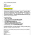
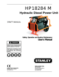
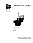
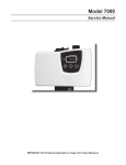
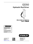
HP081523D
Hydraulic Power Unit
Saf
et
y, Oper
at
out
ine Maintenance
Safet
ety
Operat
ation
Rout
outine
ion and R
User's Manual
SERIOUS INJURY OR DEATH COULD
RESULT FROM THE IMPROPER REPAIR OR SERVICE OF THIS TOOL.
REPAIRS AND / OR SERVICE TO THIS
TOOL MUST ONLY BE DONE BY AN
AUTHORIZED AND CERTIFIED
DEALER.
Please stick
serial number
label here
Stanley Hydraulic Tools
Copyright
©
2000
The
Stanley
Works
OPS USA/CE
VERSION
41217 11/00 Ver 1
3810 SE Naef Road
Milwaukie, OR 97267-5698 USA
Phone: (503) 659-5660
Fax: (503) 652-1780
SAFETY FIRST
It is the responsibility of the operator
and service technician to read rules and
instructions for safe and proper
operation and maintenance.
A cautious worker
using common sense
is the greatest safety device
COPYRIGHT© 2000 The Stanley Works. All rights reserved.
Under copyright law, this document may not be copied in whole or in
part without the prior written consent of The Stanley Works. This exception does not permit copies to be made for others, whether or not sold.
Under the law, copying includes translating into another language,
format, or medium. This copyright notice must appear on any permitted
copies.
CONTENTS
Accessories ........................................................................................................ 13
Hydraulic Hose Requirements ............................................................................... 5
Operation ......................................................................................................... 4 - 8
Routine Maintenance ..................................................................................... 9 - 11
Parts List ...................................................................................................... 14 - 19
Safety ............................................................................................................... 2 - 3
Specifications ...................................................................................................... 13
Tool Stickers & Tags ......................................................................................... 4 -5
Troubleshooting ................................................................................................. 12
Warranty ............................................................................................................. 20
SERVICING THE HP08 POWER UNIT: This manual contains safety, operation, and routine maintenance instructions. Stanley Hydraulic Tools recommends that servicing of hydraulic tools and power units, other than routine
maintenance, must be performed by an authorized and certified dealer. Please read the following warning.
SERIOUS INJURY OR DEA
TH COULD RESUL
T FROM THE
DEATH
RESULT
IMPROPER REP
AIR OR SERVICE OF THIS EQUIPMENT
REPAIR
EQUIPMENT..
REP
AIRS AND / OR SERVICE TO THIS EQUIPMENT MUST
REPAIRS
ONL
Y BE DONE B
Y AN A
UTHORIZED AND CERTIFIED
BY
AUTHORIZED
ONLY
DEALER.
For the nearest authorized and certified dealer, call Stanley Hydraulic Tools,
1-800-972-2647/1-503-659-5660 and ask for a Customer Service Representative.
1
SAFETY
Do not operate this equipment or associated
equipment until the following safety instructions have been thoroughly read and understood! Read this manual before installing,
operating or maintaining this equipment.
Tool operators and maintenance personnel must always comply with the safety precautions given in this manual and
on the stickers and tags attached to the equipment.
These safety precautions are given for your safety. Review them carefully before operating the power unit and
before performing general maintenance or repairs.
Supervising personnel should develop additional precautions relating to the specific work area and local safety
regulations. If so, place the added precautions in the space provided on page 3.
In addition to this manual, read and understand safety and operating instructions in the Engine Operation Manual
furnished with the power unit.
GENERAL SAFETY PRECAUTIONS
The HP08 Hydraulic Power Unit will provide safe and dependable service if operated in accordance with the instructions given in this manual. Read and understand this manual and any stickers and tags attached to the power unit.
Read and understand the engine manual furnished with the unit. Failure to do so could result in personal injury or
equipment damage.
•
Operators must start in a work area without bystanders. The operator must be familiar with all
prohibited work areas such as excessive slopes and dangerous terrain conditions.
•
Establish a training program for all operators to ensure safe operation.
•
Do not operate the power unit unless thoroughly trained or under the supervision of an instructor.
•
Always wear safety equipment such as goggles, ear and head protection, and safety shoes at all times
when operating the power unit and a hydraulic tool.
•
Do not inspect or clean the power unit while the unit is running.
•
Always use hoses and fittings rated at 2500 psi/172 bar with a 4 to 1 safety factor. Be sure all hose connections
are tight and that tools are operated at the extremity of the transmission hoses connecting the tool to the power
unit.
•
Make sure all hoses are connected for correct flow direction to and from the tool being used and that the
hydraulic power suppy is compatible with the tool to be used. It is DANGEROUS to use a hydraulic tool with an
incompatible flow rate and pressure.
•
Do not inspect hoses and fittings for leaks by using bare hands. "Pin-hole" leaks can penetrate the skin.
•
.
Never operate the power unit in a closed space. Inhalation of engine exhaust can be fatal.
2
•
Do not operate a damaged or improperly adjusted power unit
•
Never wear loose clothing that can get entangled in the working parts of the power unit.
•
Keep all parts of your body away from the working parts of the power unit.
•
Always wear appropriate safety equipment such as goggles, ear protection, and toe guards. Certain tools used in
conjunction with the power unit may require other safety equipment such as breathing filters.
•
Keep clear of hot engine exhaust.
•
Do not add fuel to the power unit while the power unit is running or is still hot.
•
Do not operate the power unit if gasoline odor is present.
•
Do not use flammable solvents around the power unit engine.
•
Do not operate the power unit within 3.3 ft/1 m of buildings, obstructions, or flammable objects.
•
Allow the engine to cool before storing the power unit in an enclosure.
•
To avoid personal injury or equipment damage, all tool repair, maintenance and service must only be
performed by authorized and properly trained personnel.
LOCAL SAFETY REGULATIONS
Enter any local safety regulations here. Keep these instructions in an area accessible to the operator and maintenance personnel.
SAFETY SYMBOLS
Safety symbols are used to emphasize all operator, maintenance and repair actions which, if not strictly followed,
could result in a life-threatening situation, bodily injury or damage to equipment.
IMPORTANT
This safety symbol may appear
on the tool. It is used to alert
the operator of an action that
could place him/her or others
in a life threatening situation.
This safety symbol appears in
these instructions to identify
an action that could cause
bodily injury to the operator or
other personnel.
This safety symbol appears in
these instructions to identify
an action or condition that
could result in damage to the
tool or other equipment.
Always observe safety symbols. They are included for your safety and for the protection of the tool.
3
DECALS, STICKERS & TAGS
D A N G E R
D A N G E R
1. FAILURE TO USE HYDRAULIC HOSE LABELED AND CERTIFIED
AS NON-CONDUCTIVE WHEN USING HYDRAULIC TOOLS ON
OR NEAR ELECTRICAL LINES MAY RESULT IN DEATH OR SERIOUS INJURY.
The safety tag (p/n 15875) at right
is attached to the power unit
when shipped from the factory.
Read and understand the safety
instructions listed on this tag
before removal. We suggest you
retain this tag and attach it to the
power unit when not in use.
BEFORE USING HOSE LABELED AND CERTIFIED AS NON-CONDUCTIVE ON OR NEAR ELECTRIC LINES BE SURE THE HOSE IS
MAINTAINED AS NON-CONDUCTIVE. THE HOSE SHOULD BE
REGULARLY TESTED FOR ELECTRIC CURRENT LEAKAGE IN
ACCORDANCE WITH YOUR SAFETY DEPARTMENT INSTRUCTIONS.
2. A HYDRAULIC LEAK OR BURST MAY CAUSE OIL INJECTION
INTO THE BODY OR CAUSE OTHER SEVERE PERSONAL INJURY.
A
DO NOT EXCEED SPECIFIED FLOW AND PRESSURE FOR
THIS TOOL. EXCESS FLOW OR PRESSURE MAY CAUSE A
LEAK OR BURST.
B
DO NOT EXCEED RATED WORKING PRESSURE OF HYDRAU
LIC HOSE USED WITH THIS TOOL. EXCESS PRESSURE MAY
CAUSE A LEAK OR BURST.
C CHECK TOOL HOSE COUPLERS AND CONNECTORS DAILY
FOR LEAKS. DO NOT FEEL FOR LEAKS WITH YOUR HANDS.
CONTACT WITH A LEAK MAY RESULT IN SEVERE PERSONAL
INJURY.
D DO NOT LIFT OR CARRY TOOL BY THE HOSES. DO NOT
ABUSE HOSE. DO NOT USE KINKED, TORN OR DAMAGED
HOSE.
3. MAKE SURE HYDRAULIC HOSES ARE PROPERLY CONNECTED
TO THE TOOL BEFORE PRESSURING SYSTEM. SYSTEM PRESSURE HOSE MUST ALWAYS BE CONNECTED TO TOOL "IN" PORT.
SYSTEM RETURN HOSE MUST ALWAYS BE CONNECTED TO TOOL
"OUT" PORT. REVERSING CONNECTIONS MAY CAUSE REVERSE
TOOL OPERATION WHICH CAN RESULT IN SEVERE PERSONAL
INJURY.
4. DO NOT CONNECT OPEN-CENTER TOOLS TO CLOSED-CENTER
HYDRAULIC SYSTEMS. THIS MAY RESULT IN LOSS OF OTHER
HYDRAULIC FUNCTIONS POWERED BY THE SAME SYSTEM AND/
OR SEVERE PERSONAL INJURY.
5. BYSTANDERS MAY BE INJURED IN YOUR WORK AREA. KEEP BYSTANDERS CLEAR OF YOUR WORK AREA.
6. WEAR HEARING, EYE, FOOT, HAND AND HEAD PROTECTION.
7. TO AVOID PERSONAL INJURY OR EQUIPMENT DAMAGE, ALL TOOL
REPAIR MAINTENANCE AND SERVICE MUST ONLY BE PERFORMED BY AUTHORIZED AND PROPERLY TRAINED PERSONNEL.
I M P O R TA N T
I M P O R TA N T
READ OPERATION MANUAL AND
SAFETY INSTRUCTIONS FOR THIS
TOOL BEFORE USING IT.
READ OPERATION MANUAL AND
SAFETY INSTRUCTIONS FOR THIS
TOOL BEFORE USING IT.
USE ONLY PARTS AND REPAIR
PROCEDURES APPROVED BY
STANLEY AND DESCRIBED IN THE
OPERATION MANUAL.
USE ONLY PARTS AND REPAIR
PROCEDURES APPROVED BY
STANLEY AND DESCRIBED IN THE
OPERATION MANUAL.
TAG TO BE REMOVED ONLY BY
TOOL OPERATOR.
TAG TO BE REMOVED ONLY BY
TOOL OPERATOR.
SEE OTHER SIDE
15875
SEE OTHER SIDE
15875
SAFETY TAG P/N 15875(shown smaller than actual size)
4
HYDRAULIC HOSE REQUIREMENTS
HOSE TYPES
Hydraulic hose types authorized for use with Stanley Hydraulic Tools are as follows:
➊ Certified non-conductive
➋ Wire-braided (conductive)
➌ Fabric-braided (not certified or labeled non-conductive)
Hose ➊ listed above is the only hose authorized for use near electrical conductors.
Hoses ➋ and ➌ listed above are conductive and must never be used near electrical conductors.
HOSE SAFETY TAGS
To help ensure your safety, the following DANGER tags are attached to all hose purchased from Stanley Hydraulic
Tools. DO NOT REMOVE THESE TAGS.
If the information on a tag is illegible because of wear or damage, replace the tag immediately. A new tag may be
obtained at no charge from your Stanley Distributor.
D A N G E R
D A N G E R
1 FAILURE TO USE HYDRAULIC HOSE LABELED AND CERTIFIED AS NON-CONDUCTIVE WHEN
USING HYDRAULIC TOOLS ON OR NEAR ELECTRIC LINES MAYRESULT IN DEATH OR SERIOUS
INJURY.
FOR PROPER AND SAFE OPERATION MAKE SURE THAT YOU HAVE BEEN PROPERLY TRAINED IN
CORRECT PROCEDURES REQUIRED FOR WORK ON OR AROUND ELECTRIC LINES.
3. DO NOT EXCEED HOSE WORKING PRESSURE OR ABUSE HOSE. IMPROPER USE OR HANDLING
OF HOSE COULD RESULT IN BURST OR OTHER HOSE FAILURE. KEEP HOSE AS FAR AWAY AS
POSSIBLE FROM BODY AND DO NOT PERMIT DIRECT CONTACT DURING USE. CONTACT AT THE
BURST CAN CAUSE BODILY INJECTION AND SEVERE PERSONAL INJURY.
2. BEFORE USING HYDRAULIC HOSE LABELED AND CERTIFIED AS NON-CONDUCTIVE ON OR
NEAR ELECTRIC LINES. WIPE THE ENTIRE LENGTH OF THE HOSE AND FITTING WITH A CLEAN
DRY ABSORBENT CLOTH TO REMOVE DIRT AND MOSISTURE AND TEST HOSE FOR MAXIMUM
ALLOWABLE CURRENT LEAKAGE IN ACCORDANCE WITH SAFETY DEPARTMENT
INSTRUCTIONS.
4. HANDLE AND ROUTE HOSE CAREFULLY TO AVOID KINKING, ABRASION, CUTTING, OR CONTACT
WITH HIGH TEMPERATURE SURFACES. DO NOT USE IF KINKED. DO NOT USE HOSE TO PULL OR
LIFT TOOLS, POWER UNITS, ETC.
5. CHECK ENTIRE HOSE FOR CUTS CRACKS LEAKS ABRASIONS, BULGES, OR DAMAGE TO
COUPLINGS IF ANY OF THESE CONDITIONS EXIST, REPLACE THE HOSE IMMEDIATELY. NEVER
USE TAPE OR ANY DEVICE TO ATTEMPT TO MEND THE HOSE.
DO NOT REMOVE THIS
TA G
DO NOT REMOVE THIS
TA G
The tag shown below is attached to "certified non-conductive" hose.
6. AFTER EACH USE STORE IN A CLEAN DRY AREA.
SEE OTHER SIDE
3
SIDE 1
SEE OTHER SIDE
(shown smaller than actual size)
SIDE 2
The tag shown below is attached to "conductive" hose.
DO NOT REMOVE THIS
TA G
2. FOR PROPER AND SAFE OPERATION MAKE SURE THAT YOU HAVE BEEN PROPERLY TRAINED IN
CORRECT PROCEDURES REQUIRED FOR WORK ON OR AROUND ELECTRIC LINES.
5. CHECK ENTIRE HOSE FOR CUTS CRACKS LEAKS ABRASIONS, BULGES, OR DAMAGE TO
COUPLINGS IF ANY OF THESE CONDITIONS EXIST, REPLACE THE HOSE IMMEDIATELY. NEVER
USE TAPE OR ANY DEVICE TO ATTEMPT TO MEND THE HOSE.
6. AFTER EACH USE STORE IN A CLEAN DRY AREA.
3. DO NOT EXCEED HOSE WORKING PRESSURE OR ABUSE HOSE. IMPROPER USE OR HANDLING
OF HOSE COULD RESULT IN BURST OR OTHER HOSE FAILURE. KEEP HOSE AS FAR AWAY AS
POSSIBLE FROM BODY AND DO NOT PERMIT DIRECT CONTACT DURING USE. CONTACT AT
THE BURST CAN CAUSE BODILY INJECTION AND SEVERE PERSONAL INJURY.
4. HANDLE AND ROUTE HOSE CAREFULLY TO AVOID KINKING, CUTTING, OR CONTACT WITH
HIGH TEMPERATURE SURFACES. DO NOT USE IF KINKED. DO NOT USE HOSE TO PULL OR LIFT
TOOLS, POWER UNITS, ETC.
DO NOT REMOVE THIS
TA G
D A N G E R
D A N G E R
1 DO NOT USE THIS HYDRAULIC HOSE ON OR NEAR ELECTRIC LINES. THIS HOSE IS NOT
LABELED OR CERTIFIED AS NON-CONDUCTIVE. USING THIS HOSE ON OR NEAR ELECTRICAL
LINES MAY RESULT IN DEATH OR SERIOUS INJURY.
SEE OTHER SIDE
SEE OTHER SIDE
SIDE 1
(shown smaller than actual size)
SIDE 2
HOSE PRESSURE RATING
The rated working pressure of the hydraulic hose must be equal to or higher than the relief valve setting on the hydraulic
system.
5
OPERATION
PREPARATION FOR USE
Do not operate the power unit until you have read the
engine operating and maintenance instructions manual
furnished with the unit.
Longer hoses are not recommended. If small diameter or
long hoses are used, or if restrictive fittings are connected to the supply and return ports, the pressure
required to push the fluid through the system and back
to the hydraulic tank will be higher. If the pressure is too
high, this may cause the engine to stall. Also see
"HYDRAULIC HOSE REQUIREMENTS" earlier in this
manual.
1. ENGINE CRANKCASE OIL LEVEL
Always check the oil level before starting the engine.
Make sure the oil level is at the FULL MARK on the
dipstick. Do not overfill. Use detergent oil classified "For
Service SD, SE, SF, SG" as specified in the engine
operating and maintenance manual.
5. GENERAL
The HP08 Power Unit provides one hydraulic tool circuit
with an oil flow of 5.28 gpm/20 lpm up to 2250 psi/155 bar.
Oil flow is regulated by sliding the throttle lever to the
full throttle position.
2. ENGINE FUEL LEVEL
Check the fuel level. If low, fill with unleaded gasoline
with a minimum of 85 octane. Do not mix oil with
gasoline.
3. HYDRAULIC FLUID
Check the sight gauge on the hydraulic fluid reservoir
for the proper fiuid level. If the sight gauge indicates the
fluid level is low, add hydraulic fluid to the hydraulic oil
tank via the filler on the top.
NOTE: WHEN TOPPING UP THE HYDRAULIC TANK
IT IS ADVISABLE TO USE A STRAINER. DO NOT
OVERFILL.
The following oils are recommended for use:
ISO VG T32 SPEC for use in ambient tempertures below
32Degrees Centigrade.
ISO VG T46 SPEC for use in ambient tempertures above
32Degrees Centigrade.
4. HYDRAULIC CONNECTIONS
QUICK DISCONNECT COUPLERS
E.H.T.M.A./H.T.M.A. approved quick disconnect
couplings are installed to hydraulic hoses so that the
direction of oil flow is always from the male to the female
quick disconnect as shown on the next page. Quick
disconnect couplings and hose fittings are selected so
that additional fittings such as reducer or adapter fittings
are not required.
If adapter fittings are used, they must be approved steel
hydraulic fittings meeting a minimum operating pressure
rating of 2500 psi/172 bar. Do not use galvanized pipe
fittings or black pipe fittings.
Use thread sealant compound or bonded seals when
installing quick disconnect couplings to hose or tool
fittings. Follow the instructions furnished with the
selected thread sealant.
Facing the control valve, the left-hand male quick
disconnect fitting is the pressure (FLUID OUT) fitting.
The right-hand female quick disconnect fitting is the
return (FLUID IN) fitting.
The recommended hose length is 25 ft/8 m with a 1/2
inch/12.7 mm inside diameter. The hoses must have a
working pressure rating of at least 2500 psi/175 bar.
Each hose end must have male thread ends compatible
with E.H.T.M.A./H.T.M.A. (HYDRAULIC TOOL
MANUFACTURERS ASSOCIATION) quick disconnect
fittings (NPT type threads). (see next page)
6
Valve block on
hydraulic unit
PRESSURE
HYDRAULIC HOSE &
FITTING
CONNECTIONS
1/2 INCH BONDED SEAL (STANLEY P/N 41185)
ADAPTER, 1/2 x 3/8 INCH MALE PIPE
(STANLEY P/N 41214 )
3/8 INCH BONDED SEAL )STANLEY P/N 41184)
E.H.T.M.A./H.T.M.A. QUICK DISCONNECT COUPLER
(STANLEY P/N 41132 COUPLER CARRIER or STANLEY P/N 41131
COUPLER PROBE)
E.H.T.M.A./H.T.M.A. QUICK DISCONNECT COUPLER
(STANLEY P/N 24070 COUPLER SET - male & female)
1/2 INCH MALE PIPE HOSE END
1/2 INCH I.D. HOSE, 25 FT LONG.
(FOR 25 FEET, STANLEY P/N 05008 HYDRAULIC HOSES)
1/2 INCH MALE PIPE HOSE END
E.H.T.M.A./H.T.M.A. QUICK DISCONNECT COUPLER
(STANLEY P/N 24070 COUPLER SET - male & female)
E.H.T.M.A./H.T.M.A. QUICK DISCONNECT COUPLER
(STANLEY P/N 24069 COUPLER SET - male & female)
(STANLEY P/N 00936 ADAPTER) NOTE: AS REQUIRED
PRESSURE
RETURN
TOOL
7
DO NOT OVERTIGHTEN THE FITTINGS.
PRE-START CHECKS.
In addition to checking the fluid levels mentioned
previously the following should be observed.
1) Ensure that the Power Unit is standing on stable
ground or where necessary that it is suitable chocked for
stability.
CAUTION: DO NOT OPERATE THE MACHINE AT
AN ANGLE OF GREATER THAN 20 DEGREES (FROM
HORIZONTAL), OTHERWISE THE ENGINE
LUBRICATING SYSTEM MAY FAIL CAUSING
EXTENSIVE DAMAGE TO THE ENGINE.
2) Ensure that the engine exhaust is not obstructed and
that there is adequate ventilation to disperse the exhaust
gases.
OPERATING CHECKS.
Before commencing operation with a tool connected, the
following checks should be carried out.
1) Bypass lever is in the “FLOW’ position.
2) Check that there is no excessive engine vibrations.
3) Ensure that there are no hydraulic leaks from hoses or
couplings.
4) Check that the filter condition indicator is not within
the clogging sector. When this sector is indicated, the
return line filter should be replaced.
Depending on the ambient temperature, optimum
performance is usually achieved after 5-10 minutes
operation, this is the time required for the hydraulic oil to
reach its correct operating temperature.
3) Ensure that the transmission hoses are positioned to
avoid damage by vehicles etc., and that they will not be
understrain when the accessory tool is in use.
STOPPING THE ENGINE. NOTE:
CAUTION: ENSURE THAT THE HOSE COUPLINGS TO
THE ACCESSORY TOOLARE THOROUGHLY
CLEANED BEFORE CONNECTING. FAILURE TO DO SO
MAY CAUSE DAMAGE TO THE SEALS.
WARNING: NEVER ATTEMPT TOADD FUEL OR OIL
WHEN THE ENGINE IS RUNNING. USE ONLY THE
CORRECT GRADE AND DO NOT OVERFILL
1) Set the bypass lever to the ‘BYPASS’ position.
2) Set the ignition switch to ‘OFF’.
3) Switch off the fuel tap.
REFER TO THE ENGINE MANUAL FOR DETAILS.
STARTING THE ENGINE. NOTE:
REFER TO THE ENGINE MANUAL FOR DETAILS.
ALWAYS ENSURE THAT THE BYPASS LEVER IS IN
THE BYPASS POSITION.
1) Open the fuel tap.
2) Close the choke on the carburetor.
3) Set the engine ignition switch to ‘ON’.
4) Start the Engine by pulling on the recoil starter rope.
5) As the engine warms up, gradually return the choke to
‘OPEN’.
NOTE: THE HP08 POWER PACK IS FITTED WITH A
POWER ON DEMAND DEVICEAND THE ENGINE
WILL RUN AT IDLE SPEED UNTIL PRESSURE IS
GENERATED INTHE HYDRAULIC SYSTEM.
8
ROUTINE MAINTENANCE
ITEM
ATTENTION
10 hrs
Complete Unit.
Keep all areas clean and free from dust ,debris, etc.
*
Check security of all fasteners especially on engine
mounts.
*
Wheels and Feet. Examine for damage.
*
Transmission
Hoses.
Examine for leaks or damage.
*
Engine.
Check oil level.
*
100hrs 300 hrs
Examine mountings.
*
Examine exhaust silencer for damage or deterioration.
*
Check for excess vibration when running.
*
Change Oil/Service (Refer to notes on next page and
manufacturers instructions).
Hydraulic Tank
Check oil level.
*
Replace Filter.
*
Change Hydraulic oil.
*
Oil Cooler.
Externally clean using compressed air
DO NOT USE A WIRE BRUSH
Return line filter.
Replace as shown , or when indicator needle stays in
red zone.
Hydraulic pipes & Examine for oil leaks.
connectors.
*
*
*
9
ENGINE MAINTENANCE
Follow the maintenance schedule and general
maintenance instructions in the engine maintenance and
operation manual furnished with the power unit. Normal
maintenance includes:
•
Service air cleaner cartridge every 50 hours of
operation.
•
Clean sediment cup every 50 hours or sooner if
required.
•
Replace the spark plug every 100 hours of operation.
•
Change engine oil after first 20 hours of operation,
then after every 100 hours of operation. If engine
has been operating under heavy load or in high
ambient temperature, change the oil every 25 hours
of operation.
•
Check oil level daily.
•
Remove dirt and debris from engine with a cloth or
brush daily. Do not use water spray.
REMOVING CONDENSED MOISTURE FROM
HYDRAULIC FLUID
Condensation is a frequent problem with cool mobile
hydraulic circuits. This condition occurs in moist or cold
climates. When warm air in the hydraulic tank draws
moisture from the cooler air outside, water accumulates
in the tank.
To remove water from the hydraulic system, use the
"PRESSURE" hose without the quick-disconnect coupler
attached. Run the engine at the idle setting and pump
the fluid into a clean 5 gal./20 ltr container.
Turn the engine "OFF" as soon as the hydraulic tank
(reservoir) is empty. DO NOT operate the engine with an
empty hydraulic tank as pump damage may occur.
Allow the fluid to sit long enough for the water to settle
to the bottom of the container. Slowly pour the fluid
back into the hydraulic tank, avoiding the water at the
bottom of the container.
STORAGE
HYDRAULIC SYSTEM
MAINTENANCE
•
Clean the unit thoroughly before storage. Do not
use water pressure.
•
Always store the unit in a clean and dry facility.
Observe the following for maximum performance and
service life from the hydraulic system.
•
If the unit will be stored for a prolonged period (over
30 days), add a fuel additive to the fuel tank to
prevent the fuel from gumming. Run engine for a
short period to circulate the additive.
•
Always keep hydraulic system and fluids clean.
•
Keep water out of fluid.
•
Replace crankcase oil with new oil.
•
Keep air out of hydraulic lines. Hydraulic system
overheating and foam at the hydraulic tank breather
indicate air is present in the lines. Keep all suction
line fittings and clamps tight.
•
Remove the spark plug and pour approximately 1
ounce (30 ml) of engine oil into the cylinder. Replace
the spark plug and crank the engine slowly to
distribute the oil.
•
Hydraulic system wear is noted by increased heat
during tool operation, reduced tool performance and
eventual system breakdown.
•
•
Operate with the fluid temperature at 50 - 140 F/10 60 C for improved seal and hose life, and maximum
efficiency.
Check hydraulic reservoir for water. If water is
found, change the oil and circulate it through the
tool hose and tool. (See "HYDRAULIC SYSTEM
MAINTENANCE" earlier in this section).
•
Disconnect tool hoses. Allow the water to settle from
the fluid overnight. Install a new filter (if dirty).
10
ROUTINE CHECKS AND ADJUSTMENTS
SYSTEM PRESSURE AND FLOW CHECKS.
1. Connect a suitable hydraulic test unit to the powerpack. The unit should comprise a high
pressure flowmeter O-50 l/min (13.21 gal/min), a gauge O-200 bar (0-3OOOpsi), a temperature
gauge, and a load valve.
2. Connect the test unit to the power pack with the load valve and the By-Pass lever in the bypass position and start the power pack. Allow the engine to warm up, set the by-pass lever to the
flow position. Close the load valve completely and check that the relief valve setting is correct
(Refer to Section 2). The hydraulic oil will tend to get quite hot during this operation and therefore
the checking should be carried out as quickly as possible and the load valve opened before
excessive temperatures are reached.
3. Carefully close the load valve to raise the pressure to 100 Bar. Check that the flow rate is
between 18 and 20l/min. Adjust the engine speed to give the correct flow. DO NOT EXCEED
3600 RPM “on load” speed. If correct flow cannot be obtained within max engine speed then the
pump must be suspect, replace as necessary.
POWER ON DEMAND (P.O.D.) ADJUSTMENT
The P.O.D. Cylinder and Cable Assy are designed as a cartridge that can be disassembled
completely without disturbing any other part of the Power Pack. See diagram for breakdown
of parts.
a)
b)
Slacken the P.O.D. End Cap (Item 8) and unscrew fully.
Pull down the Nut/Cable to extract the Spring (Item 5) and Piston (Item 3) for examination.
NOTE - To connect a new Cable the piston can be withdrawn sufficiently to reveal the Grub Screw
(Item 4) which clamps the cable to the piston allowing access without extracting the ‘U’ Ring (Item 2)
from the body.
c)
The P.O.D. Body (Item 7) can be unscrewed from the Valve Block for examination if desired.
d)
The Cable can only be removed from the Tank by removal of the Clamps (Item 12). These
clamps are plastic and cannot be removed without damage. Replace the clamps upon
reassembly.
NOTE - Reassembly is the reverse of the above procedure. However, care should be taken when
fitting the 'U' Ring (Item 2) into the bore of the Body (Item 7). Standard cable length allows for the
cable to be pushed fully home into the piston before clamping by the Grub Screw (Item 4).
When unit is fully reassembled Adjuster (item 10) can be adjusted as follows: Adjustment
a)
Start engine with cable slack and check flow and pressure as detailed below
b)
Off load the machine by operating the By-pass lever.
c)
Adjust the cable tightness by using the Adjuster (item 10) until the engine speed drops to 18002200 rpm.
d)
Lock off Adjuster and check that engine reaches high speed when system pressure is raised
e)
Repeat if settings are not as specified.
11
TROUBLE SHOOTING
SYMPTOM.
POSSIBLE FAULT.
ACTION
Engine stops or will not start
Fuel tap switched off.
Switch on fuel tap.
Fuel shortage.
Refuel.
Fuel line blocked.
Clean filters/pipes.
Air vent in filter cap blocked.
Clean.
Air cleaner blocked.
Clean or renew element. Refer to
engine manual for details.
Engine malfunctions.
Refer to engine.
Low engine oil .
Top up to correct level. Refer to
engine manual for correct grade.
Insufficient oil in hydraulic tank
Top up to correct level. Refer to page
6 item 3 for details.
Engine ignition switch or connecting
wires damaged.
Check for earth leak, and renew worn
or damaged parts.
Hydraulic tank float switch damaged. Renew worn or damaged parts.
Hydraulic oil pressure low.
Accessory tool running hot
Engine speed remains at idle when
tools are operated.
Engine speed remains at full when
off load/bypass.
Hydraulic pump seized.
Renew pump.
Bypass lever is in the 'BYPASS'
position.
Set to 'FLOW'
Relief valve set low or worn.
Check relief valve settingand adjust.
Pump worn or damaged
Check system oil flow. (Ref page 11).
Renew pump as necessary.
Engine low on power
Refer to engine manual.
Oil cooler fins blocked.
Clean using air blast.
Oil cooler fan loose or damaged
Tighten or renew as necessary.
Hydraulic pump worn or damaged.
Renew pump.
Relief valve set low or worn.
Checksettingand renew as necessary.
Thermal valve malfunction.
Renew valve.
Hydraulic oil contaminated
Drain oil tank and transmission hoses
and replenish with clean oil . Replace
filters.
P.O.D. Cylinder seized in retracted
position.
Check cylinder and replace P.O.D.
unit as necessary.
P.O.D. Cable adjustment incorrect .
Re-adjust as per page 11.
Throttle lever incorrectly set at low
sp e e d .
Reset engine speed and lock throttle
lever.
P.O.D. Cylinder seized in extended
position.
Check cylinder and replace P.O.D.
unit as necessary.
P.O.D. Cable adjustment incorrect .
Re-adjust as per page 11.
12
SPECIFICATIONS
Capacity ............................................................................................................................ One 20 lpm / 5 .28gpm circuit
Pressure Range ...................................................................................................................... 70-140 bar / 1000-2000 psi
Engine RPM .................................................................................................................................................... 3600 RPM
Couplers ........................................................................................... EHTMA/HTMA Flush Face Type Male & Female
Weight (with oil) ........................................................................................................................... 66 kg / 145 lbs
Overall Length ......................................................................................................................................... 75 cm / 29.5 in.
Overall Width .......................................................................................................................................... 53 cm / 20.9 in.
Overall Height .......................................................................................................................................... 57 cm / 22.5 in.
Engine ........................................................................................................................................................ Honda 9.0 hp
Fuel Tank Capacity ...................................................................................................................................... 6 ltr / 1.6 gal
Oil Reservoir Capacity .............................................................................................................................. 6.2 ltr / 1.6 gal
................................................................................................................................................ 20 lpm @ 138 bar
Sound Power Level ............................................................................................................................. Lwa 102
ACCESSORIES
PART NO.DESCRIPTION
41128
05008
24069
24070
04182
29085
Spin-on Filter
25 feet of dual hydraulic hose (less couplers)
HTMA Flush Face Coupler Set with 3/8 NPTF threads (male & female)
HTMA Flush Face Coupler Set with 1/2 NPTF threads (male & female)
Flow & Pressure Tester
Flow & Pressure Tester with Digital Flow & Temperature Readout
13
HP081523D PARTS LIST
NOTE: Use Part Number and Part Name when ordering.
FRAME/CHASSIS ASSY
ITEM
DESCRIPTION
PART NO.
QTY
1.
2.
3.
4.
5.
6.
7.
8.
9.
10.
11.
12.
13.
14.
15.
Frame
Rivet
Washer
Handle
Chassis
Chassis Plug
Bonded Foot
Wheel
Durlok Bolt
Blanking Plug Bolt
Spring Washer
Universal Mounting Plate
Spring Washer
Set Screw
Plain Washer
41172
41158
41204
41177
41165
41119
41130
41118
41164
41196
41210
41166
41210
41198
41205
1 off
2 off
2 off
1 off
1 off
4 off
2 off
2 off
4 off
4 off
4 off
2 off
4 off
4 off
4 off
14
TANK ASSY
ITEM
DESCRIPTION
PART NO.
QTY
1.
2.
3.
4.
5.
6.
7.
8.
9.
10.
11.
12.
13.
14.
15.
16.
17.
18.
19.
20.
21.
22.
Tank
Suction Strainer
Bonded Seal
Blanking Plug Bolt
Sight Glass
Float Switch
Cap Screw
Shakeproof Washer
Cowl
Filler/Breather Unit
Set Screw
Washer
Gasket
Pressure Gauge
Pressure Gauge Seal
Capillary Hose
Rivet
Oil level label
Nameplate
Label (HYD OIL)
Noise Label (102)
Operator Warning Icons Label
41167
41127
41186
41196
41173
41136
41192
41208
41169
41176
41195
41203
41139
41115
41116
41117
41159
41628
41218
41223
41222
41224
1 off
1 off
1 off
1 off
1 off
1 off
1 off
1 off
1 off
1 off
8 off
8 off
1 off
1 off
1 off
1 off
12 off
1 off
1 off
1 off
1 off
1 off
15
VALVE BLOCK ASSY
ITEM
DESCRIPTION
PART NO.
QTY
1.
2.
3.
4.
5.
6.
7.
8,9 &10
11.
12.
13.
14.
15.
16.
17.
18.
19.
20.
21.
22.
23.
24.
25.
26.
27.
28.
29.
30.
Spool & Block Matched Pair
O Ring
Grub Screw
Boss
Lever
Knob
Dowel Pin
Relief valve seal kit
Relief Valve
Male/Male Adaptor
Bonded Seal
Bonded Seal
Adaptor
Bonded Seal
Q.R.C. Carrier
Q.R.C. Probe
H.P. Feed Pipe
Nut
Adaptor
Circlip
Filter Spigot
Filter Can
Set Screw
Shakeproof Washer
Clamping Plate
T.v. Capsule
Washer
Gasket
41161
41188
41200
41140
41141
41121
41211
41627
41153
41213
41183
41185
41214
41184
41132
41131
41182
41126
41214
41216
41122
41128
41197
41209
41135
41120
41138
41137
1 off
1 off
1 off
1 off
1 off
1 off
1 off
1 off
1 off
1 off
1 off
2 off
2 off
3 off
1 off
1 off
1 off
1 off
1 off
1 off
1 off
1 off
4 off
4 off
1 off
1 off
1 off
1 off
16
COOLER ASSY
ITEM
DESCRIPTION
PART NO.
QTY
1.
2.
3.
4.
5.
6.
7.
8.
9.
10.
11.
12.
13.
14.
Cooler
Cooler Guard
Nut
Washer
Set Screw
Cooler Return Pipe
Nut
Nut
Cooler feed Pipe
O Ring
Cap Screw
Washer
Set Screw
Shakeproof Washer
41163
41168
41191
41203
41195
41178
41125
41125
41179
41187
41192
41204
41194
41207
1 off
1 off
6 off
8 off
6 off
1 off
1 off
1 off
1 off
2 off
1 off
1 off
2 off
2 off
17
PUMP ASSY
ITEM
DESCRIPTION
PART NO.
QTY
1.
2.
3.
4.
5.
6.
7.
8.
9.
10.
11.
12.
13.
14.
15.
16.
17.
18.
19.
20.
21.
22.
23.
24.
25.
26.
27.
Engine Spacer
Grub Screw
Extension Shaft
Shakeproof Washer
Bolt
Fan
Grub Screw
Drive Coupling
Stud Coupling
Bonded Seal
Pump
Adaptor
Suction Hose Adaptor
Cap Screw
Shakeproof Washer
Nut
Washer
Pump Plate
Back-Up Ring
Jubilee clip
Suction Hose
Compact Elbow
Bolt
Shakeproof Washer
Key
Engine-Honda
Label -Speed Control Lever
41181
41201
41171
41206
41221
41160
41202
41170
41151
41185
41152
41215
41123
41193
41208
41190
41204
41129
41124
41212
41180
41157
41174
41208
41175
41282
41629
1 off
2 off
1 off
1 off
1 off
1 off
1 off
1 off
1 off
2 off
1 off
1 off
1 off
4 off
4 off
3 off
3 off
1 off
2 off
2 off
1 off
1 off
4 off
4 off
1 off
1 off
1 off
18
P.O.D. ASSY
ITEM
DESCRIPTION
1.
Spacer
2.
'U' Ring
3.
Piston
4.
Grub Screw
5.
Spring
6.
Bonded Seal
7.
Body
8.
End Cap
9.
Nut
10.
Adjuster
11.
Cable Assy
12.
Cable Clamp
13.
Cable Support Bracket
*Sold as complete 41113 POD Assembly
PART NO.
QTY
*41144
*41147
*41143
*41199
*41134
*41185
*41142
*41145
41189
41146
41148
41150
41149
1 off
1 off
1 off
1 off
1 off
1 off
1 off
1 off
1 off
1 off
1 off
2 off
1 off
19
WARRANTY
Stanley Hydraulic Tools (hereinafter called “Stanley”), subject to the exceptions contained below, warrants new hydraulic tools for a period of one
year from the date of sale to the first retail purchaser, or for a period of 2 years from the shipping date from Stanley, whichever period expires first,
to be free of defects in material and/or workmanship at the time of delivery, and will, at its option, repair or replace any tool or part of a tool, or new
part, which is found upon examination by a Stanley authorized service outlet or by Stanley’s factory in Milwaukie, Oregon to be DEFECTIVE IN
MATERIAL AND/OR WORKMANSHIP.
EXCEPTIONS FROM WARRANTY
NEW PARTS: New parts which are obtained individually are warranted, subject to the exceptions herein, to be free of defects in material and/or
workmanship at the time of delivery and for a period of 6 months after the date of first usage. Seals and diaphragms are warranted to be free of
defects in material and/or workmanship at the time of delivery and for a period of 6 months after the date of first usage or 2 years after the date of
delivery, whichever period expires first. Warranty for new parts is limited to replacement of defective parts only. Labor is not covered.
FREIGHT COSTS: Freight costs to return parts to Stanley, if requested by Stanley for the purpose of evaluating a warranty claim for warranty
credit, are covered under this policy if the claimed part or parts are approved for warranty credit. Freight costs for any part or parts which are not
approved for warranty credit will be the responsibility of the individual.
SEALS & DIAPHRAGMS: Seals and diaphragms installed in new tools are warranted to be free of defects in material and/or workmanship for a period
of 6 months after the date of first usage, or for a period of 2 years from the shipping date from Stanley, whichever period expires first.
CUTTING ACCESSORIES: Cutting accessories such as breaker tool bits are warranted to be free of defects in material and or workmanship at the
time of delivery only.
ITEMS PRODUCED BY OTHER MANUFACTURERS: Components which are not manufactured by Stanley and are warranted by their respective
manufacturers.
a. Costs incurred to remove a Stanley manufactured component in order to service an item manufactured by other
manufacturers.
ALTERATIONS & MODIFICATIONS: Alterations or modifications to any tool or part. All obligations under this warranty shall be terminated if the new
tool or part is altered or modified in any way.
NORMAL WEAR: any failure or performance deficiency attributable to normal wear and tear such as tool bushings, retaining pins, wear plates,
bumpers, retaining rings and plugs, rubber bushings, recoil springs, etc.
INCIDENTAL/CONSEQUENTIAL DAMAGES: To the fullest extent permitted by applicable law, in no event will STANLEY be liable for any incidental,
consequential or special damages and/or expenses.
FREIGHT DAMAGE: Damage caused by improper storage or freight handling.
LOSS TIME: Loss of operating time to the user while the tool(s) is out of service.
IMPROPER OPERATION: Any failure or performance deficiency attributable to a failure to follow the guidelines and/or procedures as outlined in the
tool’s operation and maintenance manual.
MAINTENANCE: Any failure or performance deficiency attributable to not maintaining the tool(s) in good operating condition as outlined in the
Operation and Maintenance Manual.
HYDRAULIC PRESSURE & FLOW, HEAT, TYPE OF FLUID: Any failure or performance deficiency attributable to excess hydraulic pressure,
excess hydraulic back-pressure, excess hydraulic flow, excessive heat, or incorrect hydraulic fluid.
REPAIRS OR ALTERATIONS: Any failure or performance deficiency attributable to repairs by anyone which in Stanley’s sole judgement caused or
contributed to the failure or deficiency.
MIS-APPLICATION: Any failure or performance deficiency attributable to mis-application. “Mis-application” is defined as usage of products for
which they were not originally intended or usage of products in such a matter which exposes them to abuse or accident, without first obtaining the
written consent of Stanley. PERMISSION TO APPLY ANY PRODUCT FOR WHICH IT WAS NOT ORIGINALLY INTENDED CAN ONLY BE
OBTAINED FROM STANLEY ENGINEERING.
WARRANTY REGISTRATION: STANLEY ASSUMES NO LIABILITY FOR WARRANTY CLAIMS SUBMITTED FOR WHICH NO TOOL REGISTRATION IS ON RECORD. In the event a warranty claim is submitted and no tool registration is on record, no warranty credit will be issued without first
receiving documentation which proves the sale of the tool or the tools’ first date of usage. The term “DOCUMENTATION” as used in this paragraph
is defined as a bill of sale, or letter of intent from the first retail customer. A WARRANTY REGISTRATION FORM THAT IS NOT ALSO ON
RECORD WITH STANLEY WILL NOT BE ACCEPTED AS “DOCUMENTATION”.
NO ADDITIONAL WARRANTIES OR REPRESENTATIONS
This limited warranty and the obligation of Stanley thereunder is in lieu of all other warranties, expressed or implied including merchantability or
fitness for a particular purpose except for that provided herein. There is no other warranty. This warranty gives the purchaser specific legal
rights and other rights may be available which might vary depending upon applicable law.
20
Stanley Hydraulic Tools • 3810 S.E. Naef Road • Milwaukie, Oregon 97267-5698
Phone: 503/659-5660 • Fax: 503/652-1780