1
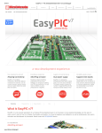
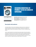
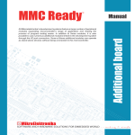
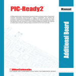
All Mikroelektronika’s development systems feature a large number of peripheral
modules expanding microcontroller’s range of application and making the
process of program testing easier. In addition to these modules, it is also
possible to use numerous additional modules linked to the development system
through the I/O port connectors. Some of these additional modules can operate
as stand-alone devices without being connected to the microcontroller.
Manual
Additional Board
EasyBee
™
MikroElektronika
EasyBee Additional Board
The EasyBee additional board is used for wireless communication between a development system and a device. Wireless
communication is enabled due to a ZigBee™ module operating at 2.4GHz and in compliance with the IEEE 802.15.4 standard.
Key features:
- ZigBee transceiver operates in compliance with the IEEE 802.15.4 standard;
- 2.4GHz operating frequency;
- 5V or 3.3V power supply voltage; and
- capable of connecting with various development systems.
How to connect the board?
Connection between the additional board and a microcontroller is established via a 2x5 connector supplied on the additional board
and a 2x5 connector on the development system, Figure 2. Communication between them is performed via a serial UART connection.
There are also six pads provided on the additional board which enable direct access to the UART pins RX, TX, RTS and CTS. These
pads can also be used to connect the USB UART board, which enables the EasyBee board to be connected to the USB port of the
PC and used over the UART Terminal software.
Pads
ZigBee module
Figure 1: EasyBee additional board
A
Figure 2: Connecting additional board
B
Figure 3: Power supply selection
How to use the board?
The additional board is powered via a development system it is connected to. In case the additional board is connected to a 5V
development system, it is necessary to place jumper J1 in the 5V position, Figure 3A. In case it is connected to a 3.3V development
system, jumper J1 should be placed in the 3.3V position, Figure 3B.
MikroElektronika
After connecting the additional board to the development system, it is necessary to select which I/O port pins on the development
system will be used for serial UART communication. It is performed by using DIP switch SW1. The position of these switches depends
on the development system in use. The bottom of the board provides a table indicating which switches on the DIP switch SW1 should
be used for the relevant development system, Figure 4, Table 1. For the proper operation of the additional board, it is necessary to load
a program into the microcontroller supplied on the development system. Program examples may be downloaded from our website at:
http://www.mikroe.com/eng/products/view/192/easybee-board/
All these programs opened in one of Mikroelektronika’s compilers contain program description with necessary settings that should be
performed for the development system in use.
UART
EasyBee
Figure 4: The back of the additional board
Development system
RX
TX
Easy-PIC
P7
P6
BIG-PIC
P7
P6
LV-18FJ
P7
P6
LV-24-33
P4
P5
Easy-dsPIC
P4
P5
dsPIC-PRO
P4
P5
Easy-AVR
P0
P1
BIG-AVR
P0
P1
Easy-8051
P0
P1
Easy-ARM
P1
P0
Table 1: Position of switches on the DIP
switch SW1
In addition to the program examples you can download from Mikroelektronika’s website, you can also write and load your own
program. The EasyBee additional board may be configured to operate as a router connected to several devices supplied with the
ZigBee module. As such, it is very useful in home automation systems with wireless communication.
Figure 5: Additional board and development system connection schematic
MikroElektronika
Figure 6: Addtional board connection schematic
MikroElektronika
MikroElektronika
MikroElektronika
If you have any questions, comments or business proposals, do not hesitate to contact us at [email protected]
If you are experiencing some problems with any of our products or just need additional information, please place your ticket at
www.mikroe.com/en/support
If you want to learn more about our products, please visit our website at www.mikroe.com
Mouser Electronics
Authorized Distributor
Click to View Pricing, Inventory, Delivery & Lifecycle Information:
mikroElektronika:
MIKROE-290