1
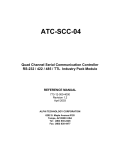
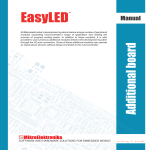
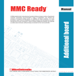
All Mikroelektronika’s development systems feature a large number of peripheral
modules expanding microcontroller’s range of application and making the
process of program testing easier. In addition to these modules, it is also
possible to use numerous additional modules linked to the development system
through the I/O port connectors. Some of these additional modules can operate
as stand-alone devices without being connected to the microcontroller.
Manual
Additional board
BeePROTO
™
MikroElektronika
BeePROTO
The BeePROTO additional board enables wireless communication via the ZigBee module whose operation is in
compliance with the IEEE802.15.4 standard. The additional board communicates to the microcontroller via UART
connection.
Key features:
- High RX sensitivity (-101 dBm);
- Up to 3 dBm output power;
- Very low power consumption (< 6 μA in deep sleep mode);
- 2.4 GHz ISM band;
- Power supply 3.3 or 5V DC.
Figure 1: BeePROTO additional board
How to connect the board?
The BeePROTO additional board is connected to a microcontroller or some other device via pads CN1. Jumper J1 is
used to select power supply voltage (3.3V or 5V) to be used to power the additional board.
The function of pins:
Tx
Rx
CTSD
RTSD
- UART receive input
- UART transmit output
- CTS output (Clear To Send) for UART hardware flow control. Active low
- RTS input (Request To Send) for UART hardware flow control. Active low
MikroElektronika
Figure 2: BeePROTO additinal board connection schematic
Figure 3: Dimensions of the BeePROTO additional board
MikroElektronika
MikroElektronika
If you have any questions, comments or business proposals, do not hesitate to contact us at [email protected]
If you are experiencing some problems with any of our products or just need additional information, please place your ticket at
www.mikroe.com/en/support
If you want to learn more about our products, please visit our website at www.mikroe.com