1
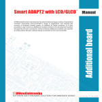
All Mikroelektronika’s development systems feature a large number of peripheral
modules expanding microcontroller’s range of application and making the
process of program testing easier. In addition to these modules, it is also
possible to use numerous additional modules linked to the development system
through the I/O port connectors. Some of these additional modules can operate
as stand-alone devices without being connected to the microcontroller.
Manual
Additional Board
MMC/SD
™
MikroElektronika
MMC/SD
MMC/SD Additional Board
A MultiMedia Card (MMC) is a memory card manufactured in Flash technology. The standard size of these cards is 24×32×1.4 mm.
MMC cards have been superseded by Secure Digital Cards (SD cards) lately, but they are still very popular and widely used because
they can be utilized with most devices that support SD cards.
Both types of cards are used as memory data storage in portable devices such as cameras, digital audio players, cellular phones, etc.
Most modern computers are supplied with an MMC/SD slot that can read both MMC and SD cards. The MMC/SD additional board
enables data read/write between a microcontroller and MMC/SD cards. Data transfer is performed via a standard Serial Peripheral
Interface (SPI). Due to built-in voltage level converters, such as 74LVCC3245, these cards may be used both with 3.3V and 5V
microcontrollers. The position of jumper J1 depends on the power supply voltage level. The MMC/SD additional board is connected to
Mikroelektronika’s development systems via a standard IDC10 connector.
Figure 1: MMC/SD additional board
Figure 3: MMC/SD additional board connection schematic
MikroElektronika
Figure 2: MMC/SD additional board connected to a development system
MMC/SD
DIP switch SW1 is used to select microcontroller pins to be used for SPI communication.
When the MMC/SD additional board is conected to EasyPIC, LV18F, EasyLV-18F, and BigPIC development systems, the following
switches on the DIP switch SW1 should be set to the ON position:
P4 -> MISO
P5 -> MOSI
P3 -> SCK
For EasyAVR and Easy8051 development systems, the following switches on the DIP switch SW1 should be set to the ON position:
P6 -> MISO
P5 -> MOSI
P7 -> SCk
For the EASYdsPIC development system, the following switches on the DIP switch SW1 should be set to the ON position:
P2 -> MISO
P3 -> MOSI
P6 -> SCK
For the Easy24-33 development system, the following switches on the DIP switch SW1 should be set to the ON position:
P2 -> MISO
P5 -> MOSI
P3 -> SCK
MikroElektronika
If you have any questions, comments or business proposals, do not hesitate to contact us at [email protected]
If you are experiencing some problems with any of our products or just need additional information, please place your ticket at
www.mikroe.com/en/support
If you want to learn more about our products, please visit our website at www.mikroe.com
Mouser Electronics
Authorized Distributor
Click to View Pricing, Inventory, Delivery & Lifecycle Information:
mikroElektronika:
MIKROE-3