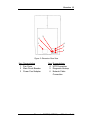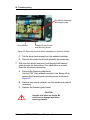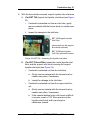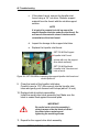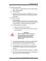
1
BST 768, SST 768, &
Dimension Elite
User Guide
2
Notice
The information in this document is subject to change without notice.
STRATASYS, INC. MAKES NO WARRANTY OF ANY KIND WITH REGARD TO THIS MATERIAL, INCLUDING, BUT NOT LIMITED TO, THE IMPLIED WARRANTIES OF MERCHANTABILITY AND FITNESS FOR A PARTICULAR PURPOSE. Stratasys, Inc. shall not be liable
for errors contained herein or for incidental or consequential damages in connection with
the furnishing, performance, or use of this material.
This equipment has been tested and found to comply with the limits for a Class A digital
device, pursuant to part 15 of the FCC Rules. These limits are designed to provide reasonable protection against harmful interference when the equipment is operated in a
commercial environment. This equipment generates, uses and can radiate radio frequency energy and, if not installed and used in accordance with the instruction manual,
may cause harmful interference to radio communications. Operation of this equipment in
a residential area is likely to cause harmful interference in which case the user will be
required to correct the interference at his own expense.
Changes or modifications to the Dimension system not expressly approved by Stratasys,
the party responsible for compliance, could void the user’s authority for use.
This document is protected by copyright. All rights reserved. Its use, disclosure, and
possession are restricted by an agreement with Stratasys per software copyright. No part
of this document may be photocopied, reproduced or translated into another language
without the prior written consent of Stratasys, Inc. Printed in the USA.
Stratasys, Dimension, and Catalyst are registered trademarks of Stratasys, Inc.
Krytox, Windows 2000, and Windows XP are registered trademarks of their respective
companies.
© Copyright 2007 Stratasys, Incorporated.
March 2007
The Dimension system conforms with the following standards, in
accordance with the EU Machinery, Low Voltage and Electromagnetic
Compatibility Directives: EU 89/392/EEC, EU 98/37/EEC, EU 73/23/EEC
amended by 93/68/EEC, EU 89/336/EEC
Dimension BST 768, SST 768, and Elite User Guide
3
Introduction
Dimension is designed with ultimate simplicity in mind. The system
enables you to build parts quickly, even if you have never used a
3D printer before. Its display panel prompts you to press a few keys
to get you modeling quickly.
The system models with ABS plastic, so modeled parts are strong
and durable. ABS also ensures that you will be able to drill, tap,
sand, and paint your creations. With the speed and convenience of
Breakaway Support Technology (BST 768) or Soluble Support
Technology (SST 768 and Elite), completed parts are quickly
available for review and test.
Dimension is an innovative combination of proprietary hardware,
software, and material technology.
Congratulations…
you made a smart choice!
Dimension BST 768, SST 768, and Elite User Guide
4
How To Use This Manual
This User’s Guide is laid out in easy to follow sections which cover
Set-up, Operation, Maintenance, and Troubleshooting of your
Dimension printer. Be sure to read each section carefully so that
you will get the best performance from your system.
Highlighted Information
The manual is written in a step-by-step format so as to guide you
through a variety of operational tasks. Information of particular
importance is presented in one of three formats
WARNING
A WARNING indicates a procedure that
may cause Injury to an operator if the
procedure is not followed. A WARNING
will precede the paragraph of instruction
to which it relates.
CAUTION
A CAUTION indicates a procedure that
may cause Damage To Equipment if the
procedure is not followed. A CAUTION
will precede the paragraph of instruction
to which it relates.
NOTE
A NOTE is used to highlight a specific point or to provide an
operational tip. While useful, a NOTE does not indicate a
procedure that can cause injury or damage if it is not
followed. A NOTE will follow the paragraph of instruction to
which it relates.
The Dimension printer guides you through operational tasks from a
User Interface (UI) on the front panel of the printer. Throughout the
User Guide, text representing messages that appear on the UI are
presented in a specific format. Interface Messages appear as
a bold, serif, fixed-pitch (mono-space) font.
Dimension BST 768, SST 768, and Elite User Guide
5
Sections Of The Manual
Overview...
Provides a quick reference for the layout of the printer and its
operating components. Overview also provides a quick reference
for sources of additional information and printer supplies.
Setup...
Guides you through the initial printer installation and setup. Topics
include unpacking, connecting power, installing software, and
connecting to a computer network. Generally, topics in setup are
only accomplished during installation or relocation of the printer.
Operation...
Further develops your understanding of the printer by presenting
the User Interface, Loading and Unloading of Material, Building
Parts, Removing Completed Parts, and Removing Support
Material. The tasks presented are common procedures
accomplished during the normal operation of the printer.
Maintenance...
Lists several tasks that you will need to perform to keep your
printer performing at its best. Some tasks are ‘As Needed’ while
others are determined by a set number of printer hours (CatalystEX
includes an odometer of printer hours). ‘House Cleaning’, Axis
Maintenance, Tip Cleaning Assembly Replacement, Chamber
Lamp Replacement, and Tip Shroud Replacement are procedures
that you can perform with the help of the User Guide.
Troubleshooting..
Allows you to perform some problem diagnosis and correction
procedures in the event that your printer has a problem. A
Troubleshooting Checklist, Fault Determination Codes, and a
procedure to recover from a Loss of Extrusion are provided.
Dimension BST 768, SST 768, and Elite User Guide
6
Dimension BST 768, SST 768, and Elite User Guide
Table of Contents 7
Table of Contents
Introduction................................................................................ 3
How To Use This Manual......................................................... 4
Highlighted Information .................................................................. 4
Sections Of The Manual................................................................. 5
Overview................................................................................... 11
Finding More Information ....................................................... 14
Setting up Dimension ................................................................... 14
Using Dimension .......................................................................... 14
Supplies ................................................................................. 15
Setup......................................................................................... 17
Workspace ............................................................................. 17
Unpacking .............................................................................. 18
Installing Forklift Access Covers ............................................ 20
Power Connections ................................................................ 20
Powering On Dimension ........................................................ 22
Insert Modeling Base ............................................................. 23
Installing Software.................................................................. 24
Networking Your Printer ......................................................... 25
Connecting Directly To Your PC ............................................ 28
Verifying Tip Depth................................................................. 30
Operation.................................................................................. 33
Display Panel and Keypad ..................................................... 33
Inserting a Modeling Base...................................................... 34
Powering On Dimension ........................................................ 34
Powering Off Dimension ........................................................ 35
Cycling Power ........................................................................ 35
Loading Material..................................................................... 36
Dimension BST 768, SST 768, and Elite User Guide
8 Table of Contents
Unloading Material .................................................................39
Building a Test Part ................................................................41
Sending Your CAD File to the System ...................................41
Building a Part from Your File ...................................................... 43
Chamber Lights ......................................................................43
Pausing Build .........................................................................44
Resuming Build from Pause Mode.........................................44
Resuming Operations from Standby Mode ............................44
Canceling a Job......................................................................45
Removing a Completed Part ..................................................45
Removing Support Material....................................................46
Breakaway Supports .................................................................... 46
Soluble Supports.......................................................................... 47
Maintenance .............................................................................49
Startup Kit Tools.....................................................................49
After Each Build......................................................................50
Empty Purge Container................................................................ 50
500 Hour Maintenance ...........................................................50
Clean Fan Filter............................................................................ 50
Tip Cleaning Assembly (Brush/Flicker Assembly) ....................... 51
2000 Hour Maintenance .........................................................52
Axis Maintenance......................................................................... 52
As Needed Maintenance ........................................................53
Remove Debris Buildup ............................................................... 53
Vacuum Build Chamber ............................................................... 53
Clean Door Glass......................................................................... 53
Chamber Lamp Replacement ...................................................... 54
Tip Shroud Replacement - SST 768 and Elite Only..................... 55
Dimension BST 768, SST 768, and Elite User Guide
Table of Contents 9
Troubleshooting ...................................................................... 59
Troubleshooting Checklist...................................................... 59
Fault Determination Codes .................................................... 61
Loss of Extrusion.................................................................... 61
Diagnosing Loss of Extrusion....................................................... 61
Recovering From Loss of Extrusion ............................................. 62
Dimension BST 768, SST 768, and Elite User Guide
10 Table of Contents
Dimension BST 768, SST 768, and Elite User Guide
Overview
Dimension builds models, including internal features, from CAD
STL files. The system builds three-dimensional parts by extruding a
bead of ABS plastic through a computer-controlled extrusion head,
producing high quality parts that are ready to use immediately after
completion. With two layer resolution settings, you can choose to
build a part quickly for design verification, or you can choose a finer
setting for higher quality surface detail.
The Dimension family consists of three 3D printers. Table 1
indicates the individual printer features.
Table 1: 3D Printer Features
Feature
BST 768
SST 768
.007 in. slice
(.178 mm)
X
.010 in. slice
(.254 mm)
X
X
.013 in. slice
(.330 mm)
X
X
P400 Model
Material
X
X
P430 Model
Material
BST
(Breakaway
Support
Material)
SST
(Soluble
Support
Material)
Elite
X
X
X
X
X
Dimension BST 768, SST 768, and Elite User Guide
12 Overview
7
1
8
2
9
10
3
4
11
5
12
6
Figure 1: Dimension Front View
Item Nomenclature
1
2
3
4
5
6
Extrusion Head
Extrusion Tips
Guide Rods
Lead Screw
Model Material Cartridge
Support Material Cartridge
Item Nomenclature
7
8
9
10
11
12
Display Panel
Tip Cleaning Assembly
Purge Container
Modeling Base
Z Platform
Platform Retainers (2)
Dimension BST 768, SST 768, and Elite User Guide
Overview 13
3
2
4
1
5
6
Figure 2: Dimension Rear View
Item Nomenclature
1
2
3
Fan Cover
Main Circuit Breaker
Power Cord Adapter
Item Nomenclature
4
5
6
UPS Connection
Diagnostic Hookup
Network Cable
Connection
Dimension BST 768, SST 768, and Elite User Guide
14 Overview
The Dimension system consists of two primary components — the
Dimension 3D printer and CatalystEX. CatalystEX is the
preprocessing software that runs on a Windows 2000 or Windows
XP Pro platform.
Dimension’s build envelope measures 203 x 203 x 305 mm (8 x 8 x
12 in). Each material cartridge contains 922 cc (56.3 cu. in.) of
usable material — enough to build continuously for about four days
without reloading.
Finding More Information
Several references are available for use with Dimension.
Setting up Dimension
Dimension User Guide
Step-by-step instructions for
installing, setting up and operating
the Dimension system.
Using Dimension
CatalystEX Online Help
Simple operating instructions for
CatalystEX are available through the
application. Help is displayed in the
Dynamic Help window ...or... you
can access them at from the Menu
Bar - Help>Contents.
World Wide Web
Additional information is available at:
http://www.dimensionprinting.com
Dimension BST 768, SST 768, and Elite User Guide
Overview 15
Supplies
This section lists all replaceable supplies used by the Dimension
modeling system. The parts mentioned in this list can be obtained
by contacting the sales representative through whom you
purchased your system.
Part Number
Description
Modeling Material - BST 768 and SST 768 Only
340-20000
White ABS Filament Cartridge
340-20200
Black ABS Filament Cartridge
340-20300
Red ABS Filament Cartridge
340-20400
Blue ABS Filament Cartridge
340-20500
Green ABS Filament Cartridge
340-20600
Yellow ABS Filament Cartridge
340-20800
Steel Gray ABS Filament Cartridge
Modeling Material - Elite Only
340-21200
Natural P430 ABS Filament Cartridge
Breakaway Support Material - BST 768 Only
340-30000
Breakaway Support Cartridge
Soluble Support Material/Concentrate - SST 768 and Elite Only
340-30200
Soluble Support Cartridge
300-00600
Soluble Soluble Concentrate (12 bottles)
Modeling Base
340-00200
Modeling Base (qty. 24)
To order supplies for your Dimension system, contact your local Dimension reseller.
Dimension BST 768, SST 768, and Elite User Guide
16 Overview
Dimension BST 768, SST 768, and Elite User Guide
Setup
Workspace
Observe the following when placing Dimension in its operating
location:
•
Dimension has an approximate weight of 128 kg (282 lbs.)
and requires a table capable of safely supporting 136 kg
(300 lbs).
•
System Dimensions:
914 x 686 x 1041 mm (36 x 27 x 41 in)
Four-inch minimum space behind unit for air circulation
•
Dedicated outlet requirements (Nominal):
100-120 VAC, 60 Hz, 15 A min. (20 amp recommended)
–or–
220-240 VAC, 50/60 Hz, 7 A min. (10 amp recommended)
•
Temperature: 18–32 C (65-90 F)
•
Relative Humidity: 30-80%, Non-condensing
•
Ethernet 10/100 Base T network
•
Network patch cable with RJ45 connectors
•
Optional UPS for power interruptions (brown-out
conditions):
Rated Power – 2200 VA
Output Power – 1600 watts
Dimension BST 768, SST 768, and Elite User Guide
18 Setup
Unpacking
This section describes the recommended procedures for
unpacking and preparing Dimension for its first use.
Unpack the printer:
WARNING
The Dimension printer weighs
approximately 128 kg (282 lbs). Use
proper moving and lifting techniques
when positioning the unit. For your
convenience, there are forklift pads built
into the bottom of the unit. They are
accessible from the side of the unit.
1.
Before unpacking the printer, move it near to its operating
location.
2. Remove the plastic banding from around the cardboard.
3. Remove the top cover. Set aside the fork access covers (2)
and bag of screws (2).
4. Remove screws (4) that attach cardboard to pallet and remove
the cardboard side panels.
5. Remove the top foam.
6. Remove outer plastic wrap - use care if using a knife so as to
not scratch the printer.
7. Remove the foam door channels (2) and tape.
WARNING
The Lead Screw and Guide Rods are
lubricated with a thin coat of Krytox
grease. Krytox grease can cause skin
irritation. Be careful not to get the grease
on your hands or clothing.
Dimension BST 768, SST 768, and Elite User Guide
Setup 19
CAUTION
Remove the foam tubes that isolate the
extrusion head from the frame (see
Figure 3). The printer will be damaged if
powered on with the foam tubes in place.
CAUTION
Be careful not to damage the rod sensors
when removing the foam tubes (see
Figure 3).
8. Remove the foam tubes that isolate the extrusion head from
the frame (see Figure 3).
Circles indicate Rod
Sensor locations.
There are also two
sensors on the back
side of the Extrusion
Head.
Foam Tubes (4)
Extrusion Head
(SST 768 & Elite
Shown)
Figure 3: Foam tubes isolating the extrusion head from the Z-axis frame
9. After unpacking, inspect the printer and report any shipping
damage to the carrier.
Dimension BST 768, SST 768, and Elite User Guide
20 Setup
Installing Forklift Access Covers
The forklift access covers can be placed over the forklift channels
after the printer is placed in its final location (see Figure 4). The
covers are press-fit in the front and held in place with one screw in
the rear.
Insert Tab in Slot
Push Cover Toward Front
of Printer
Attachment Screw
on Back of Printer
Figure 4: Installing the forklift access covers
Power Connections
This section discusses the procedure for preparing all power
connections for the printer.
CAUTION
Before connecting power to the printer,
make sure that the Dimension circuit
breaker is in the off (down) position. It is
located in the rear of the printer next to
the power cord attachment point.
Dimension is provided with two power cords: one for 110 V and one
for 220 V.
Prepare all power connections:
1. Connect the male end of the supplied power cord directly into a
grounded electrical outlet, as shown in Figure 5 on page 21. (If
using a Uninterrupted Power Supply (UPS), connect the cord
directly into the UPS).
Dimension BST 768, SST 768, and Elite User Guide
Setup 21
Figure 5: Connecting to a grounded electrical outlet
CAUTION
Do not use an extension cord or power
strip with the Dimension system.
Connect the cord directly into the
receptacle or UPS.
2. Connect the female end of the power cord directly into the rear
of the cabinet.
3. Switch the Dimension circuit breaker to the on (up) position.
Power is now supplied to the Dimension system. The system is
ready to be ‘Powered ON’.
Dimension BST 768, SST 768, and Elite User Guide
22 Setup
Powering On Dimension
WARNING
Dimension’s build chamber and
extrusion-head tip get very hot! The
chamber and head tip reach
temperatures of approximately 75 !C
(167 !F) and 280 !C (536 !F) respectively.
Personal injury can occur if proper
techniques and safety materials are not
used. Use the leather safety gloves
provided in the Startup Kit when working
inside the printer.
CAUTION
Remove the foam tubes that isolate the
extrusion head from the frame (see
Figure 3 on page 19). The printer will be
damaged if powered on with the foam
tubes in place.
Dimension’s power switch is located on the right (viewed from the
front) side cover of the cabinet, near the bottom front corner (see
Figure 6). After the switch is pushed, Dimension boots up in three
to seven minutes.
Figure 6: Location of Power Switch
(View From Right SIde of Printer)
Dimension BST 768, SST 768, and Elite User Guide
Setup 23
NOTE
If the printer was off and is at room temperature, it requires
approximately 40 minutes to warm up before you can perform
any functions. Temperatures are factory-preset and not
adjustable. The panel displays the head and envelope
temperatures while Dimension is warming up and cooling down.
NOTE
For safety, the head and Z Platform do not move while the
chamber door is open. During warm-up and operation the door is
locked. The door can be opened only when Dimension is not
building a part, getting ready to build a part, or in Pause mode.
Insert Modeling Base
Make sure retainers are turned ‘down’ - so as not to interfere with
the modeling base installation. Set the modeling base on the Z
Platform aligning the tabs on the modeling base with the slots on
the metal tray. Slide the modeling base toward the back of the unit
until its front edge (with the handle) is flush with the front edge of
the tray (see Figure 7). Secure the base with the two retainers by
turning them up.
NOTE
When inserting and removing the modeling base, use the handle
to avoid touching the top surface. Grease and oil that contact the
top build surface could cause poor part adhesion. You can clean
the build surface with isopropyl alcohol if necessary.
Slide modeling
base into the side
tray guides.
Retainer (1 of 2).
Figure 7: Inserting a modeling base
Dimension BST 768, SST 768, and Elite User Guide
24 Setup
Installing Software
There are two software programs that work with Dimension.
•
CatalystEX is the preprocessing software that controls
Dimension. If you have not already done so, you will need
to install the CatalystEX software on your PC. You will find
the CatalystEX software on the CD-ROM included in your
Startup Kit (See “Install CatalystEX:” on page 24.).
•
There is also ‘controller’ software loaded directly onto your
Dimension system from the factory. Because we do
occasionally make changes to this software, you will need
to verify that you have the latest version installed (See
“Verifying controller software version:” on page 24.). A
controller software CD is included in your Startup Kit.
Install CatalystEX:
1.
Insert the CatalystEX installation disc into your CD-ROM drive.
The installation menu automatically appears.
2. Click the Install button.
3. Follow the prompts to finish installing the software.
NOTE
CatalystEX’s installation setup allows you to change or confirm
the target installation directory. To install CatalystEX in a
directory other than the default, type the path and directory name
in the dialog box when prompted.
4. If you want to customize your installation, select the Custom
option. Custom options include the following:
•
CatalystEX Files
•
Training Files
Verifying controller software version:
5. Check the version displayed on the system keypad.
•
From Idle, press Maintenance. The version number will
be listed in the top display window under System
Maintenance.
Dimension BST 768, SST 768, and Elite User Guide
Setup 25
6. Compare the version number to the controller software CD
provided in the Startup Kit.
7. If the version on the controller software CD is newer than the
system version, follow the Controller Software Upgrade Notice
instructions provided in the Startup Kit.
Networking Your Printer
You will need to establish communication between your PC and
printer before you can send files to print. How you establish this
communication is dependent upon how your computer network is
configured. In many cases, it is a simple matter of letting the
CatalystEX software ’find’ your printer. In some situations you may
need to set the network address for your printer and, possibly,
record the IP address in the CatalystEX program.
Establishing communication on a Dynamic network:
If you are on a Dynamic network (or not sure of your network type)
follow these steps to allow the CatalystEX software to ‘find’ your
printer and establish communication.
1.
Plug in the network patch cable from your network to the rear
of Dimension. (A 14 foot network cable (blue) is included with
the Start Up Kit.)
2. Make sure the printer is ‘on’ and determine the Unique Device
Name (UDN) for your printer.
A. From Idle (or Ready to Build), press
Maintenance. The panel displays System
Maintenance and the software version.
B. Press Set Network. The top window displays: Network
Admin - Dynamic IP Address; UDN
C. The UDN for your printer is listed here. This is preset at the
factory and cannot be changed.
3. From your PC, start the CatalystEX application.
A. From the General Tab, click the ‘Manage 3D Printers’
button.
Dimension BST 768, SST 768, and Elite User Guide
26 Setup
B. Click the ‘Add from Network...’ button in the lower right
corner of the pop-up.
C. A new pop-up, ‘Add 3D Printer’, should list your printer in
the main window (identified by its UDN). Click on the
printer in this window and enter a Name and Location (your
choice) in the lower portion of the pop-up.
D. Click ‘Add Printer’ - and you are ready to go. Close the 3D
Printer pop-up.
NOTE
If your printer is not displayed in the ‘Add 3D Printer’ pop-up,
you are not using a Dynamic network. You will need to set up
a Static Network address.
If necessary, set the Static Network addresses:
1.
Obtain your network addresses from your Network
Administrator.
2. From Idle (or Ready to Build), press Maintenance.
The panel displays System Maintenance and the software
version.
3. Press Set Network. The top window displays: Network
Admin - Static IP Address; UDN
4. Press Static IP to display current settings. For example::
IP Address: 192.000.000.001
NM Address: 255.255.000.000
GW Address: 198.000.000.001
These are the factory default addresses; they must be
changed for your network.
5. Look for the cursor beneath the first digit of the IP address. The
cursor does not blink. To update the IP address:
Press Increment to increase the value one digit at a time.
Press Next Digit to move the cursor one place to the
right.
Press Last Digit to move the cursor one place to the
left.
Dimension BST 768, SST 768, and Elite User Guide
Setup 27
6. Use the three functions above to set your IP address.
7. After setting the final digit of the IP address, move the cursor
one more place to the right. The cursor moves to the NM (or
Netmask) address. Follow the same steps for setting the NM
and GW addresses.
8. When you have finished setting the addresses, press Done.
The panel displays Change IP, Netmask, Gateway?
9. Press Yes. The panel then displays Resetting Network
and after a moment returns to Idle or starts warming up.
10. If you have not done so already, plug in the network patch
cable from your network to the rear of Dimension.
11. From your PC, start the CatalystEX application.
NOTE
Detailed instructions for using CatalystEX can be found in the
CatalystEX Help file.
A. From the General Tab, click the ‘Manage 3D Printers’
button.
B. Click the ‘Add from Network...’ button in the lower right
corner of the pop-up.
C. A new pop-up, ‘Add 3D Printer’, should list your printer in
the main window (identified by its UDN). Click on the
printer in this window and enter a Name and Location (your
choice) in the lower portion of the pop-up.
D. Click ‘Add Printer’ - and you are ready to go. Close the 3D
Printer pop-up.
12. If your printer is NOT displayed in the ‘Add 3D Printer’ pop-up
(Step 11.C.), you will need to add the printer IP address
manually.
A. From the General Tab, click the ‘Manage 3D Printers’
button.
B. Click the ‘Add Manually...’ button in the lower right corner
of the pop-up.
C. In the pop-up, ‘Add 3D Printer’, enter a Name and Location
(your choice) for your printer in the appropriate fields.
Dimension BST 768, SST 768, and Elite User Guide
28 Setup
D. Enter the IP Address for your printer in the appropriate
field. It will be the same address as the one entered in Step
4.
E. Select the appropriate printer type from the drop down list.
F.
Click ‘Add Printer’ and close the 3D Printer pop-up.
13. If you are unable to connect the printer to your PC, contact
your Network Administrator.
Connecting Directly To Your PC
You can connect the Dimension printer directly to your PC without
the use of a network. This is most easily accomplished with the
printer in Dynamic network mode (as received from the factory).
1.
Connect a crossover cable from your printer directly into a
network port on your PC (A 14 foot crossover cable (orange) is
included with the Start Up Kit.)
2. Make sure the printer is ‘on’ and determine the Unique Device
Name (UDN) for your printer.
A. From Idle (or Ready to Build), press
Maintenance. The panel displays System
Maintenance and the software version.
B. Press Set Network. The top window displays: Network
Admin - Dynamic IP Address; UDN
C. The UDN for your printer is listed here. This is preset at the
factory preset and cannot be changed.
3. From your PC, start the CatalystEX application.
NOTE
Detailed instructions for using CatalystEX can be found in the
CatalystEX Help file.
A. From the General Tab, click the ‘Manage 3D Printers’
button.
B. Click the ‘Add from Network...’ button in the lower right
corner of the pop-up.
Dimension BST 768, SST 768, and Elite User Guide
Setup 29
C. A new pop-up, ‘Add 3D Printer’, should list your printer in
the main window (identified by its UDN). Click on the
printer in this window and enter a Name and Location (your
choice) in the lower portion of the pop-up.
NOTE
It may take up to 1 minute for your printer to appear in the
pop-up window.
D. Click ‘Add Printer’ - and you are ready to go. Close the 3D
Printer pop-up.
4. If your printer does not appear in the pop-up window:
A. Cancel the ‘Add 3D Printer’ pop-up and click the ‘Add
Manually’ button on the ‘3D Printers’ pop-up.
B. In the pop-up, ‘Add 3D Printer’, enter a Name and Location
(your choice) for your printer in the appropriate fields.
C. Enter the Dynamic IP Address for your printer (from Step
2B) in the appropriate field.
D. Select the appropriate printer type from the drop down list.
E. Click ‘Add Printer’ and close the 3D Printer pop-up.
F.
If you get an ‘Error: Unable to connect to printer.’ message
it may be that your PC is not configured for Dynamic
networking. To configure your PC for Dynamic networking:
i.
From the ‘Control Panel’ of your PC, choose ‘Network
and Internet Connections’.
ii.
Choose ‘Network Connections’, then double click
‘Local Area Connection’.
iii. Scroll the ‘Local Area Connection Properties’ window
to find the ‘Internet Protocol’ (TCP/IP) selection.
Double click or highlight and click the ‘Properties’
button.
iv. From the ‘General’ Tab of the ‘Internet Protocol TCP/
IP’ Properties pop-up click the ‘Obtain an IP address
automatically’ radio button.
v.
Click OK, then OK again.
Dimension BST 768, SST 768, and Elite User Guide
30 Setup
vi. After allowing your PC a minute or so to adjust to the
new setting, your PC should connect to your printer.
vii. If you are still unable to connect to your printer,
recheck your connections and settings. Contact your
local reseller for additional customer service.
Verifying Tip Depth
The system’s tip depth has been set at the factory and normally
does not need adjustment. During shipment, however, tip depth
may shift. Customers that setup and install their own systems need
to verify the tip depth setting prior to building. Building with the
wrong tip depth can result in models not adhering to the modeling
base or a loss of extrusion.
To verify tip depth:
1.
Install an unused modeling base.
2. Load Model and Support material (see “Loading Material” on
page 36.
3. Press Maintenance.
4. Press Test Parts, and select test_tipdep_plstc.cmb.
The printer will create six groups of numbers on the modeling
platform. Each individual group will consist of four number
pairs. Each number pair will have an extruded number and an
etched number. Each number pair is created at one of four Zheights: -5, 0, +5, and +10 (in .001 inches from ‘home’ level).
See Figure 8 on page 31.
NOTE
The etched number is created by the idle tip. It is normal for only
some of these numbers to be visible.
The extruded number is created at a very low flow rate and may
not show up clearly.
Dimension BST 768, SST 768, and Elite User Guide
Setup 31
Extruded Numbers - SST/Elite
Etched Numbers - SST/Elite
Etched Numbers - BST
Extruded Numbers - BST
(left side)
(right side)
-5 -5
0 0
+5+5
+10
+10
-5 -5
0 0
+5+5
+10
+10
-5 -5
0 0
+5+5
+10
+10
-5 -5
0 0
+5+5
+10
+10
-5 -5
0 0
+5+5
+10
+10
-5 -5
0 0
+5+5
+10
+10
Figure 8: Modeling base with test_tipdep_plstc.cmb model
5. Evaluate the etched numbers in each of the six groups. The
etched numbers must meet the following criteria:
•
-5 must be visible in at least one of the six groups.
•
+10 must not be visible in any of the six groups.
NOTE
The etched numbers can be difficult to see. It may be
necessary to tilt the modeling base to the light for
inspection.
It is acceptable for some groups to have NO visible etched
numbers. To meet the criteria, only one of the six groups
must have a visible -5.
6. If the tip depth does not meet the above criteria, run the model
a second time on a second unused modeling base and
evaluate again.
7. If the tip depth again fails the above criteria, contact your
Dimension service provider for more information on adjusting
tip depth.
Dimension BST 768, SST 768, and Elite User Guide
32 Setup
Dimension BST 768, SST 768, and Elite User Guide
Operation
Display Panel and Keypad
The main User Interface to Dimension is the Display Panel and
Keypad (see Figure 9).
Display Panel
Keypad
buttons
Contextsensitive
displays
Figure 9: Dimension display panel and keypad
The Dimension display panel and keypad are very easy to use,
consisting of a larger multiple-line LCD display on top, and four
single-line context-sensitive displays, each with one button (or
key). The top line in the large display always reveals the printer
status. The lower three lines of the large display show details
related to the current operation.
At times there will be an item blinking in the lower (contextsensitive) displays. The blinking item is usually the most logical
selection.
Dimension BST 768, SST 768, and Elite User Guide
34 Operation
Inserting a Modeling Base
Prior to inserting a modeling base into the tray, remove any
material buildup on and behind the Z Platform and around the lead
screw. Failure to do so could cause the modeling base to be
unlevel or, if the amount of buildup is large enough, the Z Platform
could jam at its upper limit.
Install the modeling base (See “Insert Modeling Base” on page 23.
- "Setup").
Reusing a modeling base:
The square outlines on the modeling base represent modeling
areas. The base is intended for single-use on each modeling area.
Building on a used modeling area may cause loss of extrusion or
cause a part to curl or break loose from the modeling base.
NOTE
Use CatalystEX (Pack Tab) to position a part on the modeling
base.
CAUTION
Failure to completely remove all other
layers from a previous build can cause a
head collision and result in system
damage.
Before inserting a used modeling base into the printer, make sure
that all modeling and support materials are removed from the base.
A modeling base may become worn or distorted after several
builds. The printer performs a modeling base levelness check at
the start of every part build; upon detection of a faulty modeling
base, the printer pauses and allows you to install a new one.
Powering On Dimension
Refer to “Powering On Dimension” on page 22 for instructions.
Dimension BST 768, SST 768, and Elite User Guide
Operation 35
Powering Off Dimension
To power-off Dimension, move the power switch to the OFF
position (see Figure 6 on page 22). You can do this at any time
without harming the printer. No other steps are necessary. If this is
done while the printer is building a part, the current build will be
lost. System cooling fans will continue to operate for several
minutes. This ensures a safe, systematic power down.
NOTE
For extended non-use periods, unload the material cartridges
and then power off the system.
Cycling Power
Situations may occur that require the removal of all power to the
Dimension system followed by a restart. This section discusses the
procedure for this ‘cycling’ of the electrical system.
Cycle power:
1.
Move the power switch to the OFF position (see Figure 6 on
page 22). Wait for the printer to completely power down.
2. Move the circuit breaker located on the rear of the cabinet to
the OFF (down) position.
3. Wait ten seconds and then move the circuit breaker to the ON
(up) position.
4. Move the power switch to the ON position.
5. Wait for the system to prepare itself for normal operation.
NOTE
When the system is ‘cycled’ in this manner, it may take up to 15
minutes for it to reach its normal operating state.
Dimension BST 768, SST 768, and Elite User Guide
36 Operation
Loading Material
Material cartridges are factory packaged in a box and an anti-static,
moisture-proof bag to preserve shelf life. Material will stay humidity
free inside the cartridge for at least 30 days after opening. Shelf life
is more than one year if the cartridge package remains sealed.
Load material cartridges:
1.
Remove packaging.
2. If present, remove the red sealing plug from the cartridge: (see
Figure 10)
NOTE
Plug must be removed before cartridge can be installed.
A. Turn the plug a quarter turn counter clockwise.
B. Lift up the plug to remove it from the cartridge - discard (or
recycle) the plug.
Figure 10: Remove red plug before loading
3. Find the end of the material filament taped with a “flag”.
Dimension BST 768, SST 768, and Elite User Guide
Operation 37
CAUTION
Be careful when touching the pinch roller
on the side of the cartridge. If you roll it
backwards, you could draw the material
into the cartridge (see Figure 11 for the
correct direction to move the cartridge
roller).
If this occurs, there is no way to retrieve
the filament without opening the
cartridge and exposing the material to
humidity, which reduces shelf life to a
few days.
Figure 11: Direction to move cartridge roller
4. Pull filament out of cartridge to expose about 12 inches of
material. You should easily be able to pull out the material.
NOTE
The above step makes sure that the filament will feed freely from
the spool.
5. With the cutter from your Startup Kit, snip the filament flush
with the end of the cartridge (see Figure 12 on page 38).
Dimension BST 768, SST 768, and Elite User Guide
38 Operation
Figure 12: Snipping the material filament
6. If the printer is in Idle, press the Material Load button,
which will be blinking.
7. Display will prompt with Load Model - Replace Both
Cartridges (flashing)
8. Insert material cartridges into their appropriate slot from the
front of the printer (Model material cartridge goes in the Top
slot; Support material goes in the Bottom slot).
NOTE
You might get the message, Cartridge Not Replaced Or
Invalid. This occurs if you do not insert the new cartridges
within 30 seconds. In this case the cartridge will not lock into its
slot. You must press the Retry button before continuing the
process.
9. The panel will display Load Material - Ready To Load.
Press Load to load material.
10. Watch the extrusion tips (see Figure 13 on page 39) to see if
material extrudes (purges) after loading. The panel will then
display Did Material Purge?
•
Press Yes (to continue) or No (to return to Load Material)
as appropriate — or press Purge Again if you’re unsure
which to choose.
Dimension BST 768, SST 768, and Elite User Guide
Operation 39
Support Tip
Model Tip
Figure 13: Close-up of extrusion tips
NOTE
If the display shows Load Failed, press Retry. If load fails
again, remove the cartridge, snip the material (see Figure 12 on
page 38), remove filament in the printer, and reinsert the
cartridge.
Unloading Material
The model and support material cartridges may be replaced
separately or at the same time. In idle-, load-, or build-related
modes, the panel displays the percentage of material remaining in
the cartridges. If the printer will be operating unattended for a long
period, and the material level is getting low, you may want to
replace the cartridges before starting a new part. Of course, you
will also need to replace the cartridges when they are empty.
Unload material cartridges:
1.
From Idle (or Ready To Build), Press Material Load.
A. The panel displays Load Material and prompts with,
Replace model?
•
Press Yes. to unload the Model Material.
The panel displays Replacing model,
•
Press No if you do not wish to unload the model
material.
Dimension BST 768, SST 768, and Elite User Guide
40 Operation
B. The panel then prompts with, Replace support?
•
Press Yes. to unload the Support Material.
The panel displays Replacing support,
•
Press No if you do not wish to unload the support
material.
C. After you have made the above choices, the panel displays
Unloading for approximately 60 to 75 seconds (the
selected materials will be unloaded from the extrusion
head).
D. When unloading is complete, the panel will prompt you to
remove a cartridge based upon your choices - i.e.,
Replace Both Cartridges, Replace Model
(Top) Cartridge, or Replace Support (Bottom)
Cartridge.
2. Remove the material cartridge(s) by first pushing it forward
gently, and then pulling it out of the slot.
CAUTION
Do NOT try to rewind the filament that
remains in the system. This will cause
material to cross-wind in the cartridge
causing cartridge failure.
•
When you remove a cartridge there will be approximately
180 cm (6 feet) of filament that will need to be pulled from
the system. (This is normal. Material is only retracted from
the extrusion head during ‘unloading’.)
3. To store a partially used cartridge, place a small flag of tape on
the filament near the cartridge. Cut off and discard the
remaining material. The tape flag ensures the filament does
not retract into the cartridge.
Dimension BST 768, SST 768, and Elite User Guide
Operation 41
Building a Test Part
Factory test parts have been preloaded into your Dimension. To
familiarize yourself with the system, it is recommended that you
build one of the test parts before attempting to build one of your
own files .
Once the printer has warmed up, material has been loaded, and a
modeling base is in place, you can send a test part to the printer.
Build a test part:
1.
Press Maintenance.
2. Press Test Parts, and select one of the available sample
parts.
Dimension automatically starts building the part.
3. When the part is finished, follow the steps under Removing a
Completed Part on page 45.
Sending Your CAD File to the System
This section describes the procedures used for sending your own
CAD files to Dimension.
Send a “job” to Dimension:
1.
Create an STL file with your CAD software.
2. Click on the CatalystEX icon
on the desktop of your PC.
The CatalystEX main window opens (Figure 14 on page 42).
Dimension BST 768, SST 768, and Elite User Guide
42 Operation
Figure 14: CatalystEX main window
3. From the File menu, click Open.
4. Select and Open an STL file produced with your CAD software.
5. Choose one of several options for printing your part. From the
General Tab:
NOTE
For detailed information about the many file processing options
available in CatalystEX, refer to the CatalystEX Help files.
•
Click ‘Print’ to have CatalystEX process your part and
immediately send it to your Dimension for printing.
...OR...
•
Click ‘Pack’ to have CatalystEX process the part for
printing, but not send the part to your Dimension... send
the part to the printer later as part of a pack (from the Pack
Tab).
Regardless of how you choose to prepare your file for printing,
the end result will be the same. CatalystEX will process the
STL file into a CMB file. It is the CMB file that CatalystEX will
send to the Dimension printer to create your part.
NOTE
For more information about STL files, CMB files, part orientation,
modeling envelope placement, print ’job’ efficiency, and other
print controls refer to the CatalystEX Help file.
Dimension BST 768, SST 768, and Elite User Guide
Operation 43
Building a Part from Your File
After CatalystEX sends the CMB file to the printer, the panel
displays Ready to Build along with your file’s name.
Build a part:
Press Start Model. The system will warm up to correct build
temperatures. After warm-up, the panel displays Finding Home,
(the extrusion head is currently finding the top of the modeling base
on which the part is to be built). After finding its starting point,
Dimension begins building the part.
Read the display panel while building:
The top two lines of the display panel show printer-status
messages (see Figure 15). The bottom line of the panel shows the
material amounts remaining in the cartridges.
Printer Status
Model File Name
Model Material
Remaining
Support Material
Remaining
Figure 15: Display panel during build
Chamber Lights
When a part starts to build, the chamber lights are automatically
ON. You can toggle lights ON or OFF through the Display Panel.
You can also turn the light on continuously. Go to the Idle or
Ready to Build mode. Press Maintenance and then press
Next until Setup Maintenance is displayed. Press Lights
Always. The light will remain ON until the system is powered OFF.
Dimension BST 768, SST 768, and Elite User Guide
44 Operation
Pausing Build
While building a part, you may want to pause the operation - e.g,
to allow for replacement of a material cartridge. To pause the build
operation at any time, press Pause.
NOTE
When the build process is paused, Dimension completes the
current tool path before pausing.
Resuming Build from Pause Mode
If you have pressed Pause, and are ready to resume building the
part, press Resume. Dimension resumes modeling.
Resuming Operations from Standby
Mode
After several minutes of inactivity, Dimension enters Standby
mode. During Standby, the head temperature will decrease to save
energy.
Continue operation from Standby mode:
1.
Press Resume.
•
The panel displays Ready to Build and your part’s
name (if there is a part in the queue). It also shows the
amount of material remaining in the model material
cartridge and the support material cartridge
(e.g. Mod 90 %, Sup 85 %).
•
Start Model begins blinking.
2. Press Start Model to begin modeling.
(Dimension may require a few minutes to warm up to proper
build temperatures. You can view the temperature values in the
display.)
Dimension BST 768, SST 768, and Elite User Guide
Operation 45
Canceling a Job
You can cancel a job at any time while the part is building.
Cancel a job:
1.
Press Pause.
2. Once Dimension stops building, press Cancel Build.
The panel displays Are you Sure?
3. Press Yes. The panel displays Build Stopped followed by
the part name.
4. The panel prompts you to remove the part and replace the
modeling base (See “Inserting a Modeling Base” on page 34.).
Once the chamber door has been opened and closed, the
panel asks: Part Removed?
5. Press Yes only after removing the part - refer to “Removing a
Completed Part”.
CAUTION
If you press Yes before removing the
part, the system can be damaged, and a
service call will be required.
Removing a Completed Part
When the part has completed, the panel displays Completed
Build, and the file’s name. It also shows Remove Part and
Replace Modeling Base.
Remove a completed part from the Dimension system:
1.
Open the modeling chamber door.
2. Release the modeling base retainers and pull the modeling
base towards you, out of the tray guides.
3. Insert a new modeling base.
4. Close the modeling chamber door.
Dimension BST 768, SST 768, and Elite User Guide
46 Operation
5. After you have opened and closed the door, the panel displays
Part Removed? only after removing the part, press Yes.
CAUTION
The system can be damaged if you
answer Yes and the part has not been
removed!
•
After you press Yes, the panel displays the status as
Ready to Build for the next part in the queue.
Remove a completed part from the modeling base:
1.
After removing the base from the printer, firmly flex the
modeling base back and forth with your hands to loosen the
part. For best results, flex the modeling base front-right to
back-left.
2. Pull the part off the base or use a putty knife to pry the part
completely off.
NOTE
Supports are much easier to remove when the modeling base is
still warm.
Removing Support Material
Breakaway Supports
WARNING
Wear safety goggles and LEATHER
gloves (provided in Startup Kit) when
removing breakaway supports.
Dimension BST 768 uses breakaway supports. Removing
breakaway support is a simple matter of gently removing material
by scraping, or twisting. Basic tools such as a pick or needle-nose
pliers can facilitate material removal from cavities.
Dimension BST 768, SST 768, and Elite User Guide
Operation 47
Soluble Supports
WARNING
Wear safety goggles and safety gloves
(provided in Startup Kit) when removing
soluble supports.
When removing soluble supports by
hand, wear LEATHER gloves.
When removing soluble supports with
the soluble concentrate, wear RUBBER
gloves.
Dimension SST printers (SST 768 and Elite) use soluble supports a water-based solution designed to allow you to simply wash away
the support material. Your part is left smooth and clean with the fine
details intact. The soluble support material can be removed by
hand with relative ease, but is designed to be dissolved off of your
parts for hands-free part finishing.
Refer to the ‘Soluble Support Technology (SST) Process Guide’ for
details regarding the removal of soluble support material.
Dimension BST 768, SST 768, and Elite User Guide
48 Operation
Dimension BST 768, SST 768, and Elite User Guide
Maintenance
Follow the simple procedures within this chapter to ensure
continued proper operation of Dimension.
Startup Kit Tools
The Dimension Startup Kit contains replacement parts and a set of
tools used to help you maintain the system.The following is a list of
the tools contained in the Startup Kit.
•
Needle Nose Pliers
•
Allen Wrench Set
•
Leather Insulated Gloves (Pair)
•
Putty Knife
•
Cutters
•
Soft-bristled Glue Brush
•
Brush (bronze)
•
#2 Phillips Head Screwdriver
•
Tube Anti-Seize Compound (SST 768 and Elite Only)
WARNING
Krytox grease can cause skin irritation.
Avoid contact with skin and clothing
when it is being handled.
•
2 oz. Tube Krytox Grease
Dimension BST 768, SST 768, and Elite User Guide
50 Maintenance
After Each Build
Empty Purge Container
The black, plastic purge container is attached to the right side of
the modeling envelope rear wall (see Figure 1 on page 12).
NOTE
A full purge container may impact part quality.
1.
Remove the purge container by grasping it and pushing it
upward to release it from its three mounts.
2. Pull the container towards you and out of the chamber.
CAUTION
When reinstalling the container, make
sure that it locks on all three mounts and
hangs flush with the chamber wall to
avoid damage.
3. Empty the container and reinstall on 3 mounts.
500 Hour Maintenance
NOTE
For printer hours, refer to the CatalystEX ‘Printer Services’ tab ‘Printer Info’ button.
Clean Fan Filter
To clean the fan filter:
1.
Locate the lower fan on the rear panel of Dimension and
remove the plastic frame (snaps on and off) that secures the
fan filter.
2. Clean the filter with soap and water, and blot it dry.
3. Reassemble.
Dimension BST 768, SST 768, and Elite User Guide
Maintenance 51
Tip Cleaning Assembly (Brush/Flicker Assembly)
(Refer to Figure 16 on page 52).
NOTE
The flicker should be replaced after 500 hours. It is only
necessary to replace the brush after 2000 hours.
1.
Completely power down Dimension. See "Powering Off
Dimension" on page 23.
2. Remove the purge container. See “Dimension Front View” on
page 12.
3. Remove the old flicker. - loosen the flicker attachment (rear)
screws and pull up on the flicker.
4. Insert the new flicker and tighten the rear screws while gently
pushing down on the flicker.
NOTE
The bottom of the material tip must hit in the top 75% of the
flicker.
5. Remove the old tip cleaning brush by loosening the two
mounting screws and pulling up on the brush.
6. Install the new tip cleaning brush, but do not tighten the
mounting screws.
7. With a glove on your hand, move the head so that the tips are
above the tip cleaning brush.
8. Adjust the tip cleaning assembly until the brush lightly touches
the bottom of the Model Tip Shroud. Tighten the brush
mounting screws to 12 in-lbs (1.356 Nm) of torque.
NOTE
Ideally, the top of the brush and the top of the flicker should be
the same height. Brush height, however is more important to tip
maintenance than the flicker height.
Dimension BST 768, SST 768, and Elite User Guide
52 Maintenance
Bottom of nipple
must hit brush
and top half of
exposed flicker.
Top of
brush just
touches
bottom of
Tip Shroud
Flicker Screws
Flicker
Brush
Mounting Screws
Figure 16: Replacing the tip cleaning brush
2000 Hour Maintenance
NOTE
For printer hours, refer to the CatalystEX ‘Printer Services’ tab ‘Printer Info’ button.
Axis Maintenance
1.
Clean and lubricate the Z-axis lead screw (drive screw), X-axis
guide rods (2), Y-axis guide rods (2), and Z-axis guide rods (2).
See Figure 17 for locations.
•
Clean with isopropyl alcohol.
WARNING
Krytox grease can cause skin irritation.
When it is being handled, use impervious
gloves and avoid contact with skin and
clothing.
•
Lubricate using the Krytox grease provided in the Startup
Kit. Use the grease sparingly.
Dimension BST 768, SST 768, and Elite User Guide
Maintenance 53
X-axis Guide
Rods
Y-axis Guide
Rod (1 of 2)
Z-axis Guide
Rods
Z-axis Lead
Screw
Figure 17: Lead Screw and Guide Rod Identification
As Needed Maintenance
The following maintenance items have no routine schedule but
should be tended to as needed.
Remove Debris Buildup
Remove all material buildup on the Z Platform and around the lead
screw (See “Lead Screw and Guide Rod Identification” on
page 53.). Failure to do so could cause the base to become unlevel
or the Z Platform to jam at its upper limit.
Vacuum Build Chamber
Vacuum the build chamber to remove all foreign particles and
purged material.
Clean Door Glass
The door glass can be cleaned with any commercial glass cleaner.
Dimension BST 768, SST 768, and Elite User Guide
54 Maintenance
Chamber Lamp Replacement
Replace the chamber lamp when it burns out.
NOTE
There are two chamber lamps in the modeling chamber. They are
located on the front wall of the chamber. One to the upper right,
the other to the upper left.
To replace the chamber lamp:
1.
Power down the system.
2. Pull the lamp straight out of the socket.
CAUTION
Do not touch the new bulb with bare
fingers. The natural oil of your skin can
cause premature bulb failure. Grasp the
base of the bulb instead.
Use only 24 V, 20 W bulbs.
3. Find the socket wires leading away from the socket.
4. Pull on the socket wires while inserting the two prongs of the
new lamp into the two holes of the socket. When the lamp is
seated into the socket, release the socket wires.
NOTE
Pulling on the socket wires releases the spring-loaded contacts
in the socket. If the lamp is installed without pulling on the
socket wires, the lamp might not be held securely in the socket.
Dimension BST 768, SST 768, and Elite User Guide
Maintenance 55
Tip Shroud Replacement - SST 768 and Elite Only
Due to repeated contact with the tip-wipe brush, it is normal for the
tip shroud to become worn. When chronic build up of material
around the tip area or clumps of burnt material become imbedded
in the part, replace the tip shroud.
WARNING
Head area is very hot! Use gloves when
installing a new shroud!
1.
Enter Maintenance, press Next, and access the Table
Maintenance function.
The head temperature decreases.
2. Using a 1/8-inch hex wrench, back out the two head-plate
mounting screws approximately 1/8 inch (see Figure 18). Do
not remove the screws.
3. Pull the head plate slightly away from the head until the right
side of the plate is clear of the mounting screw head.
4. Pivot the right side of the head plate upwards, and rest the
right side of the plate on the right mounting screw, as shown in
Figure 18. There is a small notch on the bottom of the plate for
this purpose.
Left
Side
Head
Plate
Mounting
Screw
Right Side
Mounting
Screw in
Retaining
Notch
Figure 18: Head plate in shroud replacement position
Dimension BST 768, SST 768, and Elite User Guide
56 Maintenance
5. Locate the shroud, the shroud-mounting screws, and shield, as
shown in Figure 19.
Shroud
Shroud
Mounting
Screws (2)
Shield
Figure 19: Shroud and shield location
6. Remove the two shroud mounting screws using a 3/32 inch
hex wrench.
WARNING
Screws are very hot!! Use gloves when
working in this area of printer!
7. Once the screws are removed, pull the metal shield down to
remove. Be careful not to bend or damage the shield.
8. Pull the shroud downward to remove it.
9. Clean the exposed tip with the bronze brush provided in the
Startup Kit.
10. Install the new shroud by pushing it up onto the tip.
NOTE
The shroud is keyed and can only be installed with the holes
offset to the rear.
11. Slide the metal shield back over the shroud.
12. Check that both the shroud and shield are positioned correctly.
NOTE
Apply a thin coat of anti-seize compound to the threads of the
shroud mounting screws.
13. Drive the two shroud-mounting screws into the shroud and
tighten, but do not over-tighten the screws!
Dimension BST 768, SST 768, and Elite User Guide
Maintenance 57
14. Lower the head cover into position, and tighten both head
cover screws.
15. Exit the Table Maintenance function.
16. Build a test part to verify system is operating correctly. See
"Building a Test Part" on page 41.
Dimension BST 768, SST 768, and Elite User Guide
58 Maintenance
Dimension BST 768, SST 768, and Elite User Guide
Troubleshooting
Troubleshooting Checklist
Problem or error message
Solution
No power
Verify power cord is securely plugged in.
Verify that the circuit breaker (at rear of system)
and the power switch (on right panel of system)
are both in the ON position.
Verify AC power is present at wall outlet.
System fails to reach operating
temperatures
Verify the system is not connected to an
extension cord or power strip.
Material not extruding
Filament may be jammed in extrusion head (see
“Loss of Extrusion” on page 61).
Purge material accumulating on
part.
Make sure that the flicker and brush are set to the
proper height. (See “Tip Cleaning
Assembly (Brush/Flicker Assembly)”
on page 51.)
Check condition of Flicker and Brush. Replace if
worn. (See “Tip Cleaning Assembly
(Brush/Flicker Assembly)” on
page 51.)
No text displayed on Display
Panel
Cycle power (see “Cycling Power” on page 35).
Cannot communicate with system
through network
Make sure network cables are connected - at the
printer, at the PC, and where cables connect to
network boxes.
Re-configure settings per (see “Networking Your
Printer” on page 25).
Dimension BST 768, SST 768, and Elite User Guide
60 Troubleshooting
Problem or error message
Solution
Cannot communicate with system
through network (Continued.)
If using a Static network address, verify that the
IP address entered in CatalystEX has the same
value as the address entered for the printer.
Your system configuration may have changed.
Contact your Network Administator.
Error Code displayed on Display
Panel
Call your local reseller for customer service. For
more information, refer to “Fault Determination
Codes” on page 61.
Display Panel displays
Build Error
Partial or bad part file sent to system. Check STL
file validity in CAD software; reprocess STL in
CatalystEX and redownload to system.
Display Panel displays
Verify a modeling base is inserted.
Can’t Find Home –
Check Modeling
Base
Modeling base may be used or defective –
replace.
Display Panel displays
The system stopped reporting its status at the
Universal Coordinated Time (UCT) shown. Wait
for the system to complete building the part. The
system will automatically restart and display Build
Complete. It is then safe to remove the model.
Communication lost
at HR:MN UCT
Display Panel displays
Could Not Read
Cartridge
Remove cartridge and cycle power (see “Cycling
Power” on page 35); reload cartridge.
Try a different cartridge.
Display Panel displays
Retry with same cartridge.
Load Failed
Try a different cartridge.
Filament may be jammed in extrusion head (see
“Loss of Extrusion” on page 61).
Dimension BST 768, SST 768, and Elite User Guide
Troubleshooting 61
Fault Determination Codes
If a fault occurs, which would prevent Dimension from executing an
operator request, the system will begin to shut down and cool. The
panel will display one or two error codes. An error-code list (with
the filename “error.txt”) can be found on the CD-ROM for the
controller software. (Because this list may change with each new
software version, make sure to use your most recent version of the
controller software on CD-ROM).
After the printer has finished cooling, the only option displayed is
Continue. Press Continue and the printer reboots and tries to
return to normal operation. If pressing Continue does not recover
the printer, the printer should be power cycled (see “Cycling
Power” on page 35); wait 60 seconds before switching power on
again. In most cases you will be able to continue operation.
However, if the printer continues to shut down and display the
same error, call your service representative.
Loss of Extrusion
Diagnosing Loss of Extrusion
Occasionally, the printer’s head may experience loss of extrusion.
This will be evident by observing one of the following:
•
Seeing the head moving with no material coming out of
either liquefier tip
•
The height of the model and support materials are not
equal
•
Sagging structures due to lack of support materials
WARNING
The head area is very hot!! Use gloves
when working in this area of printer!
Diagnose loss of extrusion:
1.
Press Cancel and remove any parts from the printer.
Dimension BST 768, SST 768, and Elite User Guide
62 Troubleshooting
2. Insert a new modeling base.
3. From Idle, enter Head Maintenance
A. Using the keypad, press Maintenance.
B. Press Next. The head will come to rest in the center of the
chamber and the Z Platform will change position. Choose
Head Maintenance.
4. Determine if there is an extrusion problem by pressing
Forward (command will be available after Head reaches
operating temperature). Watch both tips for several seconds,
looking for extrusion (material purge).
NOTE
If it was previously at a cool temperature, the tip may not
immediately extrude material. After the tip reaches operating
temperature you may need to wait up to 30 seconds before
extrusion will begin.
5. Press Stop to stop the extrusion.
6. If material steadily flowed from the tips, the head is not
experiencing loss of extrusion.
7. Return the printer to the Maintenance state - Push Done, then
answer Yes when the printer displays Is Material
Loaded?
8. If material did not extrude from both tips follow the procedure in
the following section, "Recovering From Loss of Extrusion".
Recovering From Loss of Extrusion
NOTE
It is recommended that you read and understand this entire
procedure before performing any of the work.
1.
Enter Head Maintenance mode.
•
From Idle, press Maintenance > then Next > then
Head Maintenance.
Dimension BST 768, SST 768, and Elite User Guide
Troubleshooting 63
WARNING
The head area is very hot!! Use leather
gloves when working in this area of
printer!
2. With the Phillips-head screwdriver provided in the Startup Kit,
release the two screws securing the head assembly (see
Figure 20 - the screws require only ¼ turn to release). Swing
open the front half of the head.
NOTE
You may feel resistance when you swing open the front half of
the head. One, or both, of the material filament lines are likely to
still be routed into the head and held by the drive motor. This is
normal. Swing the door open slowly, but firmly.
Swivel Head
Screws (2)
Figure 20: Location of swivel head screws (2)
(Head shown is SST 768 & Elite - Screw location is the same for BST 768)
3. Attempt to re-establish extrusion.
NOTE
Both material filaments must be coming out of the feed tubes at
the back of the head (see Figure 21) and still be going into the
drive block funnels in the front half of the head in order to
proceed with this step. If not, skip to step 4.
A. Run both filament motors forward while gently pushing the
filament that stopped extruding into the filament guide
rollers. Do so for about three seconds.
Dimension BST 768, SST 768, and Elite User Guide
64 Troubleshooting
B. If the purge was successful:
i.
Continue to run both filament motors forward and
slowly swivel the head closed. Be careful to not pinch
the filament or the head wiring when closing the head.
ii.
Once the head is closed, tighten both of the swivel
head screws, ¼ turn.
iii. Verify material continues to extrude through both tips
for an additional 30 seconds, then press Stop to halt
extrusion.
iv. Push Done. The panel displays Is material
loaded?
v.
Press Yes. The panel displays Exiting
maintenance and you can now resume normal
operation. (Skip Steps 4 through 13.)
C. If material did not purge, continue with the following steps.
4. Snip both filaments approximately 1 inch from the fixed part of
the head (see Figure 21).
Figure 21: Materials coming out of feed tubes
NOTE
On rare occasions, the material may NOT be extending out from
the feed tubes. If this occurs, push in the appropriate cartridge to
unlatch it. Pull out the cartridge to expose the filament and
manually feed the filament through the feed tubes until the
Dimension BST 768, SST 768, and Elite User Guide
Troubleshooting 65
filament comes through the back of the head. Pull the filament
from the head while inserting the cartridge. Once the cartridge
latches, pull an additional 6 inches of filament through the head
(to make sure the filament is not caught at the cartridge receiver).
Then snip the filament approximately 1 inch from the fixed part of
the head.
5. Remove the filament from both drive block assemblies if there
is enough to remove by hand.
A. Select Reverse.
This causes the drive wheels to reverse, so the material
filaments can be backed out of the liquefier.
B. Grasp the filament from the drive blocks with your
fingertips, and gently pull it out of the drive wheels. Repeat
for second filament. If you are unable to easily remove
either filament, leave the filament in the drive block for
now.
6. Remove both drive block assemblies from the swivel part of the
head.
A. Set a material cartridge on top of the tray to support the
removed drive block assemblies.
B. Remove the support drive block first. Use a 7/64” Allen
wrench to remove the two screws securing the motor
assembly as shown in Figure 22.
Dimension BST 768, SST 768, and Elite User Guide
66 Troubleshooting
Drive Block Assembly
Mounting Screws
Model Drive
Drive Wheels
Support Drive
Filament Guide Funnel
and Mounting Screw
Figure 22: Removing the drive block assemblies to check for buildup
C. Set the drive block assembly on the material cartridge.
D. Remove the model drive block assembly the same way.
7. With the drive blocks removed, look through both filament
guide funnels for obstructions. If an obstruction is present,
clear the drive block obstruction:
A. Remove the filament guide funnel.
Use the 7/64” Allen wrench provided in the Startup Kit to
remove the filament-guide mounting screw as shown in
Figure 22.
B. Remove any excess material; use the needle-nose pliers if
necessary.
C. Replace the filament guide funnel.
CAUTION
Liquefier inlet tubes are fragile. Be
careful not to damage them when
removing material.
Dimension BST 768, SST 768, and Elite User Guide
Troubleshooting 67
8. With the drive blocks removed, inspect liquefier tube inlet area.
A. (For BST 768) Inspect the liquefier inlet tubes (see Figure
23).
i.
If material is extended out from an inlet tube, gently
remove material with the bronze brush or needle-nose
pliers.
ii.
Inspect for damage to the inlet tube.
BST 768 Support Liquefier
Inlet Tube
(shown with only the support
drive block removed)
BST 768 Model Liquefier
Inlet Tube will look the same.
Figure 23: BST 768 - Inspecting the liquefier inlet tubes
B. (For SST 768 and Elite) Inspect the model liquefier inlet
tube, and the support inlet funnel covering the support
liquefier inlet tube (see Figure 24).
i.
If material is extended out from the inlet tube:
a. Gently remove material with the bronze brush or
needle-nose pliers, if necessary.
b. Inspect for damage to the inlet tube.
i.
If material is extended out from the support inlet funnel:
a. Gently remove material with the bronze brush or
needle-nose pliers, if necessary.
b. If the material buildup in the inlet funnel is difficult
to remove, insert a 1/16” Allen wrench into the
liquefier inlet funnel and try pushing the
obstruction forward.
Dimension BST 768, SST 768, and Elite User Guide
68 Troubleshooting
c.
If this doesn’t work, remove the liquefier inlet
funnel using a 1/4” nut driver. Dissolve support
material from the funnel with the soluble support
solution.
NOTE
It is typical for material to build up around the
support liquefier inlet tube under the inlet funnel. Do
not remove this material unless it interferes with
reinstallation of the inlet funnel.
d. Inspect for damage to the support inlet tube.
e. Replace the liquefier inlet funnel.
SST 768 & Elite Support
Liquefier Inlet Funnel
(shown with only the support
drive block removed)
SST 768 & Elite Model
Liquefier Inlet Tube does not
have a funnel.
Figure 24: SST 768 & Elite- Inspecting the support liquefier inlet funnel and
model liquifier inl
9. Clean the inside of the liquefier inlet tubes.
Carefully insert a 1/16” Allen wrench into the liquefier inlet
tubes and gently push forward until it stops (about 1/4 inch).
10. Replace both drive-block assemblies.
Install the model drive block assembly first. Make sure the
block is seated flush against the swivel plate.
IMPORTANT
Be careful not to pinch the assembly’s
wiring harness under the block or behind
the motor before replacing and
tightening the mounting screws.
11. Repeat for the support drive block assembly.
Dimension BST 768, SST 768, and Elite User Guide
Troubleshooting 69
12. Clean the drive wheels.
A. Press Select Drive repeatedly until the display shows
Both Drive Motors.
B. Press Reverse.
C. With the glue brush provided in the Startup Kit, clear any
material buildup from each drive by brushing its serrated
drive wheel.
13. Check for Extrusion.
A. Press Forward.
Pull out 6 inches of material from the fixed head housing.
Feed the filament into the drive blocks and look at the tips
to verify material is extruding through both liquefiers.
B. If the filament does not extrude:
i.
Stop the motors and return to Step 4.
ii.
If, after two tries the material fails to extrude, call your
service provider.
IMPORTANT
While closing the head, be careful not to
crimp the filament, and make sure that
the head wiring doesn’t get pinched
between the swivel head and the rear
head housing.
C. If the purge was successful, continue to run both filament
motors forward and slowly swivel the head closed.
D. Once the head is closed, tighten both ¼ turn screws.
E. Verify material continues to extrude through both tips for
an additional 30 seconds, and then press Stop to halt
extrusion.
F.
Push Done. The panel displays Is material loaded?
G. Press Yes. The panel displays Exiting maintenance
and you can resume normal operation.
Dimension BST 768, SST 768, and Elite User Guide
14950 Martin Drive
Eden Prairie, MN 55344 USA
Telephone: (952) 937-3000
Fax: (952) 937-0070
Web Site: www.dimensionprinting.com
Stratasys Document # 204400-0002