1
Instruction Manual
Supplement to Functional Safety Inverters
High Performance, Multifunction Inverter
This manual is the translation of the original instruction of the original manual, a supplement to the FRENIC-MEGA
Instruction Manual (INR-SI47-1223-E, INR-SI47-1335-E,INR-SI47-1457-E), contains descriptions that exclusively
apply to the functional safety inverter FRENIC-MEGA (Inverter type: FRN_ _ _G1-). For other descriptions, refer to
the FRENIC-MEGA Instruction Manual.
The functional safety inverter FRENIC-MEGA is compliant with European Safety Standard : EN61800-5-2 SIL2 and EN
ISO13849-1 PL=d Cat. 3.
To comply with the requirements, refer to the original manual, Chapter 9, Section 9.3 "Compliance with EMC Standards" and
Section 9.5 "Compliance with the Low Voltage Directive in the EU" in conjunction with this manual.
Checking the inverter's ROM version
The inverter's ROM version can be checked on Menu #5 "Maintenance Information" (5_14 ) as a 4-digit code. For the
detailed keypad operation, refer to the inverter original manuals.
About newly added functions
The functions listed below are newly added to the FRENIC-MEGA series of inverters having a ROM version 3600 or later. For
details about those functions, refer to Section 2 "Details of Function Codes Added" or the PG Interface Card Instruction
Manual.
Inverter's ROM Version
Newly Added Functions
3600 or later
(1) Online tuning
Performs tuning while the motor is rotating in order to cover the motor speed
fluctuation caused by the temperature rise of the motor.
(2) Function extension of brake signal
Extends the brake-ON sequence function.
(3) PG error processing
Changes the PG error detection width if the speed command exceeds the base
frequency.
(4) Synchronous operation
Enables synchronous operation of two motors equipped with a pulse generator (PG).
The PG interface card (OPC-G1-PG or OPC-G1-PG22) is required. For details,
refer to the PG Interface Card Instruction Manual.
(5) Motor magnetic flux weakening control under "vector control without speed sensor"
Improves the torque control stability. The overspeed detection level can be
specified.
(6) Improved regenerative power control under vector control
Adjusts the motor magnetic flux level to be applied during deceleration under vector
control.
(7) Terminal command "Enable battery operation" BATRY
(Function code data = 59)
Cancels the undervoltage protection so that the inverter under an undervoltage
condition runs the motor with battery power.
(8) "0 to 20 mA" range added to analog input/output
(9) Speed limit level adjustable with analog inputs under torque control
(10) Adjustable ACR P gain under "vector control"
The PG interface card OPC-G1-PG22 is applicable to inverters having a ROM version 3510 or later.
Fuji Electric Co., Ltd.
INR-SI47-0551-E
1
Copyright © 2011 Fuji Electric Co., Ltd.
All rights reserved.
No part of this publication may be reproduced or copied without prior written permission from Fuji Electric Co., Ltd.
All products and company names mentioned in this manual are trademarks or registered trademarks of their respective holders.
The information contained herein is subject to change without prior notice for improvement.
2
List of Errata
The table below provides a list of errata for the FRENIC-MEGA Instruction Manuals (INR-SI47-1183b-E, INR-SI47-1223c
-E, INR-SI47-1334-E, INR-SI47-1335a-E and INR-SI47-1457-E).
Page
1183b 1223c 1334 1335a 1457
vii
-
v
-
-
Wrong
Correct (underlined)
Fuse rating column (IEC number):
(FRN3.7G1■-2□/FRN3.7G1■-4□ or
lower models)
IEC60269-1
Current rating in the fuse rating column:
(FRN55G1■-4□)
400 (IEC60269-4)
ix
-
vi
-
IEC60269-2
350 (IEC60269-4)
Standard in item 9: EN60204 Appendix
C.
IEC60364-5-52
Note to be added.
In a power supply system (I-T NET) where a
neutral point is not grounded, the control
terminals are provided with basic insulation
from the mains. If a person may touch them
directly, an external insulation circuit should
be added for double insulation.
-
Grounding terminal can accept one wire only.
I/O Check Item, 4_15, 4_17
Shows the pulse rate (p/s) of the A/B
phase signal…
Shows the pulse rate of the A/B phase
signal…
(e.g., 1000 p/s is expressed as 1.00.)
3-15
-
3-12
-
-
5-7
-
5-7
-
-
Drive control of E31,E32
Torque control: N
Torque control: Y
0.00 to 400.00%
5-10
-
5-9
-
-
C32, C37, C42
Data setting range: 0.00 to 200.00%
-
-
5-10
-
-
P56
Default setting: 85%
85% (90% for inverters of 132 kW or above)
H13
Data setting range: 0.1 to 10.0 s
0.1 to 20.0 s
Drive control of H15
w/o PG: Y
w/ PG: Y
w/o PG: N
w/ PG: N
H46
Data setting range: 0.1 to 10.0 s
0.1 to 20.0 s
H80
Data setting range: 0.00 to 0.40
Drive control: Torque Control :Y
0.00 to 1.00
Torque Control : N
Drive control of H92, H93
w/o PG: Y
w/ PG: Y
w/o PG: N
w/ PG: N
A56, b56, r56
Default setting: 85%
85% (90% for inverters of 132 kW or above)
5-12
-
5-11
-
-
5-12
-
5-11,
5-100
-
-
5-14
5-14
5-12,
5-109
5-12
5-15
5-14
-
5-12
-
-
5-16,
5-18,
5-20
-
5-14,
5-16,
5-18
-
-
5-22
5-22
-
5-22
5-19
5-19
-
5-19
-
d55
Data setting range: 0, 1
d55
Default setting: 0
-
d68
Default setting: 40
0000 to 00FF (in hex.)
0000
4.0
3
Page
1183b 1223c 1334 1335a 1457
Wrong
Correct (underlined)
H81, H82: Light Alarm Selection 1 and 2
"PID feedback wire break" to be added.
5-85,
5-87
-
5-110,
5-111
-
-
Addition of Light Alarm Factor
Code: cof
Name: PID feedback wire break
Description: The PID feedback signal wire(s)
is broken.
Table 5.2 Light Alarm Selection 2 (H82),
Bit Assignment of Selectable Factors
Bit: 3
Code: cof
Content: PID feedback wire break
5-92
-
-
-
-
-
5-117
-
5-127
-
8-2
8-2
to
to
8-4
8-4
-
Table 5.5 Function Codes to be Switched
Last line
Reserved: d57 A57, b57, r57
-
J62 PID Control (PID control block
selection)
Table
When J62 = 0, 1: Absolute value (Hz)
When J62 = 2,3: Ratio (%)
-
Noncompliance note to be added to
"Applicable safety standards C22.2 No.
14."
4
P57, A57, b57, r57
When J62 = 0, 1: Ratio (%)
When J62 = 2,3: Absolute value (Hz)
The following inverters are not compliant with
C22.2 No. 14.
FRN160G1■-4□ to FRN220G1■-4□
FRN355G1■-4□, FRN400G1■-4□
Chapter 2
2.3.2 Terminal arrangement diagram and screw specifications
(2) Arrangement of control circuit terminals (common to all inverter types)
Terminal type
Recommended wiring size (mm2)*
Screw size: M3 (0.7 N·m)
0.75
Spring (screwless)
0.65 to 0.82 (AWG 19 or 18)
* Using wires exceeding the recommended sizes may lift the front cover depending upon the
number of wires used, impeding keypad's normal operation.
5
2.3.5 Wiring of main circuit terminals and grounding terminals
This section shows connection diagrams with the Enable input function used.
(1) FRN_ _ _G1-2A/2U/4A/4U, with SINK mode input by factory default
(2) FRN_ _ _G1-4E, with SOURCE mode input by factory default
6
*1 Install a recommended molded case circuit breaker (MCCB) or residual-current-operated protective device (RCD)/earth leakage circuit
breaker (ELCB) (with overcurrent protection function) in the primary circuit of the inverter to protect wiring. Ensure that the circuit
breaker capacity is equivalent to or lower than the recommended capacity.
*2 Install a magnetic contactor (MC) for each inverter to separate the inverter from the power supply, apart from the MCCB or RCD/ELCB,
when necessary.
Connect a surge absorber in parallel when installing a coil such as the MC or solenoid near the inverter.
*3 The R0 and T0 terminals are provided for inverters with a capacity of 1.5 kW/2 HP or above.
To retain an alarm output signal ALM issued on inverter's programmable output terminals by the protective function or to keep the keypad
alive even if the main power has shut down, connect these terminals to the power supply lines. Without power supply to these terminals,
the inverter can run.
*4 Normally no need to be connected. Use these terminals when the inverter is equipped with a high power-factor, regenerative PWM
converter (RHC series).
*5 When connecting an optional DC reactor (DCR), remove the jumper bar from the terminals P1 and P(+).
Inverters with a capacity of 55 kW/100 HP in LD mode and inverters with 75 kW/125 HP or above require a DCR to be connected. Be
sure to connect it to those inverters.
Use a DCR when the capacity of the power supply transformer exceeds 500 kVA and is 10 times or more the inverter rated capacity, or
when there are thyristor-driven loads in the same power supply line.
*6 Inverters with a capacity of 7.5 kW/15 HP or below have a built-in braking resistor (DBR) between the terminals P(+) and DB.
When connecting an external braking resistor (DBR), be sure to disconnect the built-in one.
*7 A grounding terminal for a motor. Use this terminal if needed.
*8 For control signal wires, use twisted or shielded-twisted wires. When using shielded-twisted wires, connect the shield of them to the
common terminals of the control circuit. To prevent malfunction due to noise, keep the control circuit wiring away from the main circuit
wiring as far as possible (recommended: 10 cm/3.9 inches or more). Never install them in the same wire duct. When crossing the control
circuit wiring with the main circuit wiring, set them at right angles.
*9 The connection diagram shows factory default functions assigned to digital input terminals [X1] to [X7], [FWD] and [REV], transistor
output terminals [Y1] to [Y4], and relay contact output terminals [Y5A/C] and [30A/B/C].
*10 Switching connectors in the main circuits. For details, refer to "Instruction manual for FRENIC-MEGA Section 2.3.4 Switching
connectors" later in this section.
*11 Slide switches on the control printed circuit board (control PCB). Use these switches to customize the inverter operations. For details,
refer to Instruction manual for FRENIC-MEGA Section 2.3.6 "Setting up the slide switches."
*12 When the Enable input function is not to be used, keep terminals [EN1]-[PLC] and terminals [EN2]-[PLC] short-circuited using jumper
wires. For opening and closing the hardware circuit between terminals [EN1] and [PLC] and between [EN2] and [PLC], use safety
components such as safety relays and safety switches that comply with EN954-1 or EN ISO13849-1 Category 3 or higher.
*13 To bring the inverter into compliance with the European Standard, Low Voltage Directive EN61800-5-1, be sure to insert the specified
fuse (see Instruction manual for FRENIC-MEGA page v) in the primary circuit of the inverter.
2.3.6 Wiring for control circuit terminals
In general, the covers of the control signal wires are not specifically designed to withstand a high voltage (i.e., reinforced
insulation is not applied). Therefore, if a control signal wire comes into direct contact with a live conductor of the main
circuit, the insulation of the cover might break down, which would expose the signal wire to a high voltage of the main
circuit. Make sure that the control signal wires will not come into contact with live conductors of the main circuit.
Failure to observe these precautions could cause electric shock or an accident.
Noise may be emitted from the inverter, motor and wires.
Take appropriate measures to prevent the nearby sensors and devices from malfunctioning due to such noise.
An accident could occur.
Connecting/disconnecting wires to/from a control circuit terminal of spring(screwless) type
Strip the wire end by 8 to 10 mm/0.31 to 0.39 inch as shown below.
Strip length of wire end
Type of screwdriver (tip shape)
8 to 10 mm
0.31 to 0.39 inch
Flat (0.6 × 3.5 mm/0.024 × 0.14 inch)
For strand wires, the strip length specified above should apply after twisting of them.
If the strip length is out of the specified range, the wire may not be firmly clamped or may be short-circuited with
other wires.
Twist the end of the stripped wires for easy insertion and insert it firmly into the wire inlet on the control circuit terminal. If
the insertion is difficult, hold down the clamp release button on the terminal with a flat screwdriver.
When disconnecting the wires from the terminal, hold down the clamp release button on the terminal with a flat
screwdriver and pull out the wires.
Connecting wire to terminal
Disconnecting wire from terminal
Flat screwdriver
Wires
Wires
Wire
E inlet
Clamp release button
7
Table 2.7 lists the symbols, names and functions of the control circuit terminals. The wiring to the control circuit terminals
differs depending upon the setting of the function codes, which reflects the use of the inverter. Route wires properly to reduce
the influence of noise.
Classification
Table 2.7 Symbols, Names and Functions of the Control Circuit Terminals
Symbol
Analog input
[C1]
Name
Functions
Analog setting
current input
(1) The frequency is commanded according to the external current input.
• 4 to 20 mA DC/0 to 100% (Normal operation)
• 20 to 4 mA DC/0 to 100 % (Inverse operation)
(2) In addition to frequency setting, PID command, PID feedback signal, auxiliary
frequency command setting, ratio setting, torque limiter level setting, or analog input
monitor can be assigned to this terminal.
(3) Hardware specifications
• Input impedance: 250Ω
• The maximum input is +30 mA DC, however, the current larger than +20 mA DC is
handled as +20 mA DC.
PTC/NTC
thermistor
input
(1) Connects PTC (Positive Temperature
Coefficient)/NTC (Negative Temperature
Coefficient) thermistor for motor protection.
Ensure that the slide switch SW5 on the control
PCB is turned to the PTC/NTC position (see
Instruction manual for FRENIC-MEGA Section
2.3.6 "Setting up the slide switches").
Digital input
The figure shown at the right illustrates the
internal circuit diagram where SW5 (switching
the input of terminal [C1] between C1 and
PTC/NTC) is turned to the PTC/NTC position.
For details on SW5, refer to Instruction manual
for FRENIC-MEGA Section 2.3.6 "Setting up
the slide switches." In this case, you must
change data of the function code H26.
[X1]
Digital input 1
[X2]
Digital input 2
[X3]
Digital input 3
[X4]
Digital input 4
[X5]
Digital input 5
[X6]
Digital input 6
[X7]
Digital input 7
[FWD]
Run forward
command
[REV]
Run reverse
command
Figure 2.10 Internal Circuit Diagram
(SW5 Selecting
PTC/NTC)
(1) Various signals such as "Coast to a stop," "Enable external alarm trip," and "Select
multi-frequency" can be assigned to terminals [X1] to [X7], [FWD] and [REV] by
setting function codes E01 to E07, E98, and E99. For details, refer to Chapter 5,
Section 5.2 "Details of Function Codes."
(2) Input mode, i.e. SINK/SOURCE, is changeable by using the slide switch SW1. (Refer
to Instruction manual for FRENIC-MEGA Section 2.3.6 "Setting up the slide
switches.")
(3) Switches the logic value (1/0) for ON/OFF of the terminals [X1] to [X7], [FWD], or
[REV]. If the logic value for ON of the terminal [X1] is 1 in the normal logic system,
for example, OFF is 1 in the negative logic system and vice versa.
(4) Digital input terminal [X7] can be defined as a pulse train input terminal with the
function codes.
Maximum wiring length 20 m/66 ft
Maximum input pulse 30 kHz: When connected to a pulse generator with open collector
transistor output
(Needs a pull-up or pull-down resistor. See notes on
page 2-22.)
100 kHz: When connected to a pulse generator with
complementary transistor output
For the settings of the function codes, refer to FRENIC-MEGA User's Manual, Chapter
5 "FUNCTION CODES."
(Digital input circuit specifications)
Item
Min.
Operating voltage
(SINK)
0V
2V
OFF level
22 V
27 V
Operating voltage
(SOURCE)
ON level
22 V
27 V
OFF level
0V
2V
2.5 mA
5 mA
Operating current at ON
(Input voltage is at 0 V)
(For [X7])
Allowable leakage current at
OFF
Figure 2.13 Digital Input Circuit
8
Max.
ON level
(9.7 mA) (16 mA)
−
0.5 mA
Classification
Table 2.7 Symbols, Names and Functions of the Control Circuit Terminals (Continued)
Symbol
[EN1]
Name
Functions
Enable input
[EN2]
(1) Turning off the circuit between terminals [EN1] and [PLC] or terminals [EN2] and
[PLC] stops the inverter's output transistor. (Safe Torque Off: STO)
(2) These terminals are exclusively used for the source mode input and cannot be
switched to the sink mode.
(3) If either one of these input terminals is kept OFF for 50 ms or more, the inverter
interprets it as a discrepancy, causing an alarm ecf. This alarm state can be cleared
only by turning the inverter power off and on.
<Digital input circuit specifications>
<Control circuit>
+24 VDC
[PLC]
Item
Photocoupler
[EN1]
Operating voltage
6.3 k
Min.
Max.
ON level
22 V
27 V
OFF level
0V
2V
2.5 mA
5 mA
−
0.5 mA
Operating current at ON
(Input voltage is at 27 V)
[EN2]
Allowable leakage current at OFF
6.3 k
[PLC]
PLC signal
power
(1) Connects to the power supply of PLC output signals.
Rated voltage: +24 VDC (Allowable range: +22 to +27 VDC), Maximum 100 mA DC
(2) This terminal also supplies power to the load connected to the transistor output
terminals. Refer to "Transistor output" described later in this table for more.
[CM]
Digital input
common
Common terminal for digital input signals
This terminal is electrically isolated from the terminals [11]s and [CMY].
Using a relay contact to turn [X1] to [X7], [FWD], or [REV] ON or OFF
Figure 2.14 shows two examples of a circuit that uses a relay contact to turn control signal input [X1] to
[X7], [FWD], or [REV] ON or OFF. In circuit (a), the slide switch SW1 is turned to SINK, whereas in circuit
(b) it is turned to SOURCE.
Note: To configure this kind of circuit, use a highly reliable relay.
(Recommended product: Fuji control relay Model HH54PW.)
<Control circuit>
<Control circuit>
[PLC]
SINK
SINK
[PLC]
SOURCE
SOURCE
[X1] t o [X7],
[FWD], [REV]
+24 VDC
+24 VDC
Digital input
[CM]
[X1] to [X7],
[FWD], [REV]
Photocoupler
[CM]
Photocoupler
[CM]
(a) With the switch turned to SINK
(b) With the switch turned to SOURCE
Figure 2.14 Circuit Configuration Using a Relay Contact
Using a programmable logic controller (PLC) to turn [X1] to [X7], [FWD], or [REV] ON or OFF
Figure 2.15 shows two examples of a circuit that uses a programmable logic controller (PLC) to turn control
signal input [X1] to [X7], [FWD], or [REV] ON or OFF. In circuit (a), the slide switch SW1 is turned to
SINK, whereas in circuit (b) it is turned to SOURCE.
In circuit (a) below, short-circuiting or opening the transistor's open collector circuit in the PLC using an
external power supply turns ON or OFF control signal [X1] to [X7], [FWD], or [REV]. When using this type
of circuit, observe the following:
- Connect the + node of the external power supply (which should be isolated from the PLC's power) to
terminal [PLC] of the inverter.
- Do not connect terminal [CM] of the inverter to the common terminal of the PLC.
9
Name
Programmable
logic controller
Functions
Programmable
logic controller
<Control circuit>
[PLC]
SINK
[PLC]
SOURCE
SINK
SOURCE
[X1] t o [ X7],
[FWD], [REV]
[X1] to [X7],
[FWD], [REV]
Photocoupler
Photocoupler
[CM]
[CM]
Digital input
<Control circuit>
+24 VDC
Symbol
+24 VDC
Classification
Table 2.7 Symbols, Names and Functions of the Control Circuit Terminals (Continued)
(a) With the switch turned to SINK
(b) With the switch turned to SOURCE
Figure 2.15 Circuit Configuration Using a PLC
For details about the slide switch setting, refer to Instruction manual for FRENIC-MEGA Section 2.3.6 "Setting up
the slide switches."
For inputting a pulse train through the digital input terminal [X7]
• Inputting from a pulse generator with an open collector transistor output
Stray capacity on the wiring between the pulse generator and the inverter may disable transmission of the
pulse train. As a countermeasure against this problem, insert a pull-up resistor between the open collector
output signal (terminal [X7]) and the power source terminal (terminal [PLC]) if the switch selects the
SINK mode input; insert a pull-down resistor between the output signal and the digital common terminal
(terminal [CM]) if the switch selects the SOURCE mode input.
A recommended pull-up/down resistor is 1kΩ 2 W. Check if the pulse train is correctly transmitted because
stray capacity is significantly affected by the wire types and wiring conditions.
[FM1]
[FM2]
Analog
monitor
Both terminals output monitor signals for analog DC voltage (0 to +10 V) or analog DC
current (+4 to +20 mA). The output form (VO/IO) for each of [FM1] and [FM2] can be
switched with the slide switches on the control PCB and the function codes, as listed
below.
Terminal
[FM1]
Analog output
[FM2]
Output form
Terminal function is
Content is
specified by:
Analog DC voltage Analog DC current specified by:
Slide switch SW4
VO1
IO1
Function code
F31
Function code F29
0
1
Slide switch SW6
VO2
IO2
Function code
F35
Function code F32
0
1
The signal content can be selected from the following with function codes F31 and F35.
• Output frequency
• Output current
• Output voltage
• Output torque
• Load factor
• Input power
• PID feedback amount
• Speed (PG feedback value) • DC link bus voltage
• Universal AO
• Motor output
• Calibration
• PID command
• PID output
* Input impedance of the external device: Min. 5kΩ (at 0 to 10 VDC output)
(While the terminal is outputting 0 to 10 VDC, it is capable of driving up to two analog
voltmeters with 10 kΩ impedance.)
* Input impedance of the external device: Max. 500Ω (at 4 to 20 mA DC output)
* Adjustable range of the gain: 0 to 300%
[11]
Analog
common
Two common terminals for analog input and output signals.
These terminals are electrically isolated from terminals [CM] and [CMY].
10
Chapter 3 Monitoring the running status -- Menu #3 "Drive Monitoring" -Listed below are monitoring items added or modified in the FRENIC-MEGA series of inverters having a ROM version
3000 or later.
LED
monitor
shows:
Item
3_17
Target position pulse
(synchronous operation)
3_18
Current position pulse
(synchronous operation)
Current deviation pulse
(synchronous operation)
3_19
Unit
Description
Pulse
Shows the target position pulse for synchronous operation.
Shows the current position pulse for synchronous
operation.
Shows the current deviation pulse for synchronous
operation.
Pulse
Pulse
3_20
Control status monitor
(synchronous operation)
--
3_26
Positioning deviation
(synchronous operation)
degree
Shows the current control status.
0: Synchronous operation disabled
20: Synchronous operation canceled
21: Synchronous operation stopped
22: Waiting for detection of Z phase
23: Z phase of reference PG detected
24: Z phase of slave PG detected
25: Synchronization in progress
26: Synchronization completed
Shows the positioning deviation (in degree) for
synchronous operation.
Note
Difference of notation between standard keypad and remote keypad
Descriptions in this manual are based on the standard keypad having a four-digit, 7-segment LED monitor (shown in the
original FRENIC-MEGA Instruction Manuals, Chapter 3). The FRENIC-MEGA also provides a multi-function keypad as an
option, which has an LCD monitor and a five-digit, 7-segment LED, but has no USB port.
If the standard keypad is replaced with an optional multi-function keypad, the display notation differs as shown below.
Function
code
Name
H42
Capacitance of DC Link Bus Capacitor
H44
Startup Counter for Motor 1
H47
Initial Capacitance of DC Link Bus Capacitor
H79
Preset Startup Count for Maintenance (M1)
A52
Startup Counter for Motor 2
b52
Startup Counter for Motor 3
r52
Startup Counter for Motor 4
d15
Feedback Input (Encoder pulse resolution)
Standard keypad
d60
Command (Pulse Rate Input) (Encoder pulse resolution)
H43
Cumulative Run Time of Cooling Fan
H48
Cumulative Run Time of Capacitors on Printed Circuit
Boards
H77
Service Life of DC Link Bus Capacitor (Remaining time)
H78
Maintenance Interval (M1)
H94
Cumulative Motor Run Time 1
A51
Cumulative Motor Run Time 2
b51
Cumulative Motor Run Time 3
r51
Cumulative Motor Run Time 4
d78
Synchronous Operation (Excessive deviation detection
range)
Hexadecimal notation
Decimal notation
Display in units of 10
hours
Display by hours
Display in units of 10
pulses.
(For 10000 pulses or
more: Display in units
of 100 pulses, with the
x10 LED ON)
11
Multi-function keypad (TP-G1-J1)
Display in units of 10 pulses
Chapter 5
Change when
running
Data
copying
Chapter 5-1 Function Code Tables
Listed below are function codes added or modified in the FRENIC-MEGA series of inverters having a ROM version 3600 or
later.
Default
setting
Y
Y
0
Y
Y
Y
Y
Y
5
17: Positional deviation in synchronous operation
F31 Analog Output [FMA]/[FM1]
(Function)
*1
Y
Y
0
N
Y
N
Y
N
5
F32 Analog
Y
Y
0
Y
Y
Y
Y
Y
5
Y
Y
0
N
Y
N
Y
N
5
Y
Y
Y
Y
Y
5
Code
F29 Analog
Name
Output
*1
Data setting range
[FMA]/[FM1] 0: Output in voltage (0 to 10 VDC)
(Mode selection) 1: Output in current (4 to 20 mA DC)
Drive control
Refer
to
PG w/o w/ Torque page:
V/f
V/f PG PG control
2: Output in current (0 to 20 mA DC)
Output
[FM2] 0: Output in voltage (0 to 10 VDC)
(Mode selection)
1: Output in current (4 to 20 mA DC)
2: Output in current (0 to 20 mA DC)
F35 Pulse
Output
*1 Analog Output [FM2]
[FMP]
(Function)
E01 Terminal [X1] Function
N
Y
0
E02 Terminal [X2] Function
59 (1059): Enable battery operation
(BATRY)
N
Y
1
5
E03 Terminal [X3] Function
N
Y
2
5
E04 Terminal [X4] Function
N
Y
3
5
E05 Terminal [X5] Function
N
Y
4
5
E06 Terminal [X6] Function
N
Y
5
5
E07 Terminal [X7] Function
N
Y
*3
5
E08 Terminal [X8] Function
N
Y
7
N
Y
8
*2
E09 Terminal [X9] Function
*2
E20 Terminal [Y1] Function
N
Y
0
E21 Terminal [Y2] Function
29 (1029): Synchronization completed
(SY)
N
Y
1
8
E22 Terminal [Y3] Function
N
Y
2
8
E23 Terminal [Y4] Function
N
Y
7
8
E24 Terminal [Y5A/C] Function
N
Y
15
8
E27 Terminal [30A/B/C] Function
N
Y
N
Y
N
8
N
Y
99
E61 Terminal [12] Extended Function
17: Speed limit FWD
N
Y
0
Y
Y
Y
Y
Y
8
E62 Terminal [C1] Extended Function
18: Speed limit REV
N
Y
0
Y
Y
Y
Y
Y
8
N
Y
0
Y
Y
Y
Y
Y
8
N
Y
98
Y
Y
Y
Y
Y
5
N
Y
99
Y
Y
Y
Y
Y
5
N
Y
0
Y
Y
Y
Y
Y
8
E63 Terminal [V2] Extended Function
E98 Terminal [FWD] Function
59 (1059): Enable battery operation
E99 Terminal [REV] Function
C40 Terminal [C1] Range Selection
0: 4 to 20 mA
(BATRY)
8
1: 0 to 20 mA
Y
Y
0
Y
N
N
N
N
8
H81 Light Alarm Selection 1
P05 Motor 1
0000 to FFFF (hex.)
Y
Y
0
Y
Y
Y
Y
Y
9
H82 Light Alarm Selection 2
0000 to FFFF (hex.)
Y
Y
0
Y
Y
Y
Y
Y
9
Y
Y
0
Y
N
N
N
N
8
A19 Motor 2
(Online tuning) 0: Disable 1: Enable
(Online tuning) 0: Disable 1: Enable
b19 Motor 3
(Online tuning) 0: Disable 1: Enable
Y
Y
0
Y
N
N
N
N
8
r19 Motor 4
(Online tuning) 0: Disable 1: Enable
Y
Y
0
Y
N
N
N
N
8
A46 Speed Control 2
I (Integral time) 999: Disable integral action
Y
Y
0.100
N
Y
Y
Y
N
9
b46 Speed Control 3
I (Integral time) 999: Disable integral action
Y
Y
0.100
N
Y
Y
Y
N
9
r46 Speed Control 4
I (Integral time) 999: Disable integral action
Y
Y
0.100
N
Y
Y
Y
N
9
N
Y
0
J96 Brake Signal
0 to 31
(Speed condition selection)
d04 Speed Control 1
9
Bit 0: Criterion speed for brake-ON
(0: Detected speed, 1: Reference speed)
N
N
Y
Y
N
Bit 1: Reserved.
N
N
N
N
N
Bit 2: Response for brake-OFF current
(0: Slow response, 1: Quick response)
Y
Y
Y
Y
N
Bit 3: Criterion frequency for brake-ON
(0: Stop frequency (F25),
1: Brake-ON frequency (J71))
N
N
Y
Y
N
Bit 4: Output condition of brake signal
(0: Independent of a run command ON/OFF
1: Only when a run command is OFF)
N
N
Y
Y
N
N
Y
Y
Y
N
I (Integral time) 999: Disable integral action
Y
Y
0.100
*1 [FM1] and [FM2] for Asia (FRN_ _ _G1-A), EU (FRN_ _ _G1-E) and USA (FRN_ _ _G1-U) versions
*2 Terminals [X8] and [X9] not provided on Asia (FRN_ _ _G1-A), EU (FRN_ _ _G1-E) or USA (FRN_ _ _G1-U) version
*3
"8" for Asia (FRN_ _ _G1-A), EU (FRN_ _ _G1-E) and USA (FRN_ _ _G1-U) versions; "6" for other versions
12
9
Change when
running
Data
copying
Code
Default
setting
999: Disable integral action
Y
Y
0.100
N
Y
Y
Y
N
9
0: Continue to run 1
N
Y
2
N
Y
Y
Y
N
11
Y
Y
999
N
Y
Y
Y
Y
12
N
Y
0
13
Name
Data setting range
d12 Speed Control (Jogging)
Drive control
Refer
to
PG w/o w/ Torque page:
V/f
V/f PG PG control
I (Integral time)
d23 PG Error Processing
1: Stop running with alarm 1
2: Stop running with alarm 2
3: Continue to run 2
4: Stop running with alarm 3
5: Stop running with alarm 4
d35 Overspeed Detection Level
0
to
999: Depends on setting of d32 or d33
d41 Application-defined Control
0: Disable (Ordinary control)
d60 Command
120%
Y
Y
Y
Y
Y
1: Enable (Constant peripheral speed control)
N
Y
N
N
N
2: Enable (Simultaneous synchronization, without Z phase)
N
Y
N
Y
N
3: Enable (Standby synchronization)
N
Y
N
Y
N
4: Enable (Simultaneous synchronization, with Z phase)
N
Y
N
Y
N
0014
to
(Encoder pulse resolution) (20 to 3600 pulses)
0E10
(hex.)
N
Y
0400
(1024)
N
Y
N
Y
N
13
d71 Synchronous
Operation 0.00 to 1.50 times
(Main speed regulator gain)
Y
Y
1.00
N
Y
N
Y
N
13
d72
13
Y
Y
15.00
N
Y
N
Y
N
d73
(APR positive output limiter) 20 to 200%, 999: No limiter
(APR P gain) 0.00 to 200.00 times
Y
Y
999
N
Y
N
Y
N
13
d74
(APR negative output limiter) 20 to 200%, 999: No limiter
Y
Y
999
N
Y
N
Y
N
13
13
d75
Y
Y
1.00
N
Y
N
Y
N
d76
(Synchronous offset angle) 0 to 359 degrees
Y
Y
0
N
Y
N
Y
N
13
d77
(Synchronization completion 0 to 100 degrees
detection angle)
Y
Y
15
N
Y
N
Y
N
13
Y
Y
65535
*4
N
Y
N
Y
N
13
d78
(Z phase alignment gain) 0.00 to 10.00 times
(Excessive deviation detection 0 to 65535 (Display in units of 10 pulses)
range) (For 10000 or more: Display of the upper four digits in units
of 100 pulses)
Y
Y
1
-
-
-
-
-
-
d82 Magnetic Flux Weakening Control
0: Disable
(Vector control without speed sensor)
1: Enable
Y
Y
1
N
N
N
N
Y
13
d83 Magnetic Flux Weakening Low
10 to 70%
Limiter (Vector control without speed
sensor)
Y
Y
40%
N
N
N
N
Y
13
-
d81 Reserved
0 or 1
d84 Reserved
0 to 20 dB
Y
Y
5 dB
-
-
-
-
-
d85 Reserved
0 to 200%
Y
Y
95%
-
-
-
-
-
-
d90 Magnetic Flux Level during
Deceleration (Vector control)
100 to 300%
Y
Y
150%
N
N
Y
Y
N
14
d91 ACR P gain (Vector control)
0.00 to 2.00, 999
Y
Y
999
N
N
Y
Y
Y
14
d92 Reserved
0.00 to 3.00
Y
Y
0.00
-
-
-
-
-
-
d98 Reserved
0000 to FFFF (hex.)
Y
Y
0000
Y
Y
N
N
N
d99 Function Extension 1
0 to 31
Y
Y
0
Bit 0: Reserved
-
-
-
-
-
Bit 1: Reserved
-
-
-
-
-
Bit 2: Reserved
-
-
-
-
-
Bit 3: JOG (Ready for jogging) via the communications link
(0: Disable, 1: Enable)
Y
Y
Y
Y
N
Bit 4: Reserved
U01 Customizable Logic:
(Input 1) 29 (1029): Synchronization completed
U02 Step 1
(SY)
14
-
-
-
-
-
N
Y
N
Y
N
N
Y
0
(Input 2)
N
Y
0
8
8
U06 Customizable Logic:
(Input 1)
N
Y
0
8
U07 Step 2
(Input 2)
N
Y
0
8
U11 Customizable Logic:
(Input 1)
N
Y
0
8
U12 Step 3
(Input 2)
N
Y
0
8
U16 Customizable Logic:
(Input 1)
N
Y
0
8
U17 Step 4
(Input 2)
N
Y
0
8
U21 Customizable Logic:
(Input 1)
N
Y
0
8
U22 Step 5
(Input 2)
N
Y
0
8
U26 Customizable Logic:
(Input 1)
N
Y
0
8
U27 Step 6
(Input 2)
N
Y
0
8
U31 Customizable Logic:
(Input 1)
N
Y
0
8
U32 Step 7
(Input 2)
N
Y
0
8
*4 The standard keypad displays 6553 on the LED monitor and lights the x10 LED.
(For USA (FRN_ _ _G1-U) version, the standard keypad is Multi-function keypad (TP-G1W-J1).)
13
Change when
running
Data
copying
Default
setting
U36 Customizable Logic:
(Input 1)
N
Y
0
U37 Step 8
(Input 2)
N
Y
0
8
U41 Customizable Logic:
(Input 1)
N
Y
0
8
Code
Name
Data setting range
Drive control
Refer
to
PG w/o w/ Torque page:
V/f
V/f PG PG control
8
U42 Step 9
(Input 2)
N
Y
0
8
U46 Customizable Logic:
(Input 1)
N
Y
0
8
U47 Step 10
(Input 2)
N
Y
0
N
Y
100
Y
Y
Y
Y
Y
5
U82 Customizable Logic Output Signal 2
N
Y
100
Y
Y
Y
Y
Y
5
U83 Customizable Logic Output Signal 3
N
Y
100
Y
Y
Y
Y
Y
5
U84 Customizable Logic Output Signal 4
N
Y
100
Y
Y
Y
Y
Y
5
U85 Customizable Logic Output Signal 5
N
Y
100
Y
Y
Y
Y
Y
5
U81 Customizable Logic Output Signal 1 59 (1059): Enable battery operation
(Function selection)
14
(BATRY)
8
Chapter 5-2
Details of Function Codes Added
F29
Analog output [FMA]/[FM1] (Mode selection) *
F32
Analog output [FM2] (Mode selection) *
* [FM1] and [FM2] are for Asia (FRN_ _ _G1-A), EU (FRN_ _ _G1-E) and USA (FRN_ _ _G1-U) versions.
Versions except Asia (FRN_ _ _G1-A), EU (FRN_ _ _G1-E) and USA (FRN_ _ _G1-U)
versions
Mode selection (F29)
F29 specifies the property of the output to terminal [FMA]. You need to set switch SW4 on the control printed circuit
board (control PCB).
Data for F29
Position of slide switch SW4
mounted on the control PCB
[FMA] output form
Current (0 to +20 mA DC)
2
IO
Asia (FRN_ _ _G1-A), EU (FRN_ _ _G1-E) and USA (FRN_ _ _G1-U) versions
Mode selection (F29 and F32)
F29 and F32 specify the property of the output to terminals [FM1] and [FM2], respectively. You need to set the slide
switches on the control printed circuit board (control PCB).
Terminal [FM1]
Output form
Terminal [FM2]
Data for F29
Position of slide switch
SW4 on the control
PCB
Data for F32
Position of slide switch
SW6 on the control
PCB
2
IO1
2
IO2
Current (0 to +20 mA DC)
F31
Analog Output [FMA]/[FM1] (Function) *
F35
Pulse
Output
Analog Output [FM2] (Function) *
[FMP]
(Function)
* [FM1] and [FM2] are for Asia (FRN_ _ _G1-A), EU (FRN_ _ _G1-E) and USA (FRN_ _ _G1-U) versions.
These function codes enable monitoring of deviation in angle in synchronous operation. For details about synchronous
operation, refer to the PG Interface Card Instruction Manual.
Data for
F31
Data for
F35
17
[FMA]/[FM1] output
Function
(Monitor the
following)
[FMP]/[FM2] output
Positional deviation in
synchronous operation
Meter scale
(Full scale at 100%)
Deviation in angle
E01 to E09 Terminal
[X1]
E01 to E07
Terminal [X1] to [X7] Function *
0% to 50% to 100%,
representing -180° to 0° to +180° of the deviation
to
[X9]
E98
E99
Terminal
Terminal [REV] Function
U81 to U85
Customizable Logic Output Signal 1 to 5 (Function selection)
Function
[FWD]
Function
* Terminals [X8] and [X9] are not provided on Asia (FRN_ _ _G1-A), EU (FRN_ _ _G1-E) or USA (FRN_ _ _G1-U) version.
Function code data
Drive control
Active
ON
Active
OFF
V
/f
P
G
V
/f
w
/o
P
G
w
/
P
G
To
rqu
e
co
ntr
ol
59
1059
Y
Y
Y
Y
Y
Terminal commands assigned
Enable battery operation
Symbol
BATRY
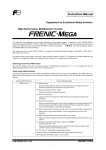
Enable battery operation -- BATRY (Function code data = 59)
15
Related
function
codes
Turning this terminal command ON cancels the undervoltage protection so that the inverter runs the motor with battery
power under an undervoltage condition.
When BATRY is assigned to any digital input terminal, the inverter trips after recovery from power failure just as F14 =
1 regardless of F14 setting. When BATRY is ON, the main power down detection is disabled regardless of H72 setting.
16
Prerequisites for battery operation
(1) The terminal command BATRY (data = 59) must be assigned to any digital input terminal.
(2) A DC link bus voltage must be supplied from the battery to the main circuit (L1/R-L3/T or L2/S-L3/T) as
shown in Figures A and B given below.
(3) A regulated voltage (sine-wave or DC voltage) must be supplied to the auxiliary power supply (R0-T0).
(4) For 200 V class series / 230V class series for USA of 37 kW / 60 HP or above and 400 V ones / 460V ones for
USA of 75 kW / 125 HP or above, a regulated voltage (sine-wave) must be supplied to the auxiliary fan
power supply (R1-T1) as shown in Figure B. The fan power supply connector must be configured for battery
operation as shown in Figure C.
(5) The BATRY-assigned terminal (data = 59) must be turned ON at the same moment as closing of MC2.
Figure A
Connection Diagram
for 200 V Class Series of 30 kW
(230V Ones of 50HP for USA)
or Below
and 400 V Ones of 55 kW
(460V Ones of 100HP for USA)
or Below
Figure B
Connection Diagram
for 200 V Class Series of 37 kW
(230V Ones for USA of 60HP)
or Above
and 400 V Ones of 75 kW
(460V Ones for USA of 125HP)
or Above
17
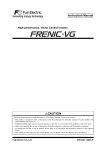
Setting
Usage
CN R (Red)
CN W (White)
CN W (White)
When not using R1 or T1
(Factory default)
CN R (Red)
When using R1 and T1 (BATRY operation)
Figure C Fan Power Supply Switching Connector
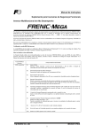
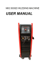
About battery operation (when BATRY is ON)
(1) The undervoltage protective function (lu ) is deactivated.
(2) The inverter can run the motor even under an undervoltage condition.
(3) The RDY ("Inverter ready to run") output signal is forcedly turned OFF.
(4) The bypass circuit of the charging resistor comes to be closed (73X ON) after a delay of time T1 from when
the BATRY is turned ON. Further, after a delay of time T2 (a maximum of 0.1 second), the battery operation
starts. For the specifications of T1, see the table below.
Main power
MC1
ON
ON
BATRY
MC2
73X
Battery power supply
ON
ON
ON
ON
ON
T1
LU
RDY
T2
Battery operationenabled zone
ON
ON
DC link bus voltage Edc
Undervoltage level
Detected speed
Reference Frequency
S-curve acce./dece. disabled
0
Run command
ON
Battery Operation Timing Diagram
T1 from BATRY ON to 73X ON
Power condition
30 kW / 50
HP or below
After the control power supply goes OFF, the battery
100 ms
power and control power are turned ON.
The control power remains ON or after a momentary
205 ms
power failure happens.
37 kW / 60
HP or above
500 ms
(5) The S-curve acceleration/deceleration is disabled.
(6) The battery operation speed can be calculated by the following formula.
Reference speed (pre - ramp) during battery operation ≤
Battery voltage - 5[V ]
× Rated speed × k
2 × Rated voltage
Where,
Battery voltage: 24 VDC or higher for 200 V class series / 230 V class series for USA
48 VDC or higher for 400 V class series / 460 V class series for USA.
Rated speed :
F04
Rated voltage : F05 (Motor rated voltage (V))
k:
Safety coefficient (Less than 1, about 0.8)
Precautions
(1) The battery power supply must be connected before or at the same moment as turning ON of BATRY.
(2) As shown in the timing diagram above, battery operation is possible within the battery operation-enabled
zone. There is a delay of "T1 + T2" after the BATRY, MC2, and battery power supply are turned ON.
18
(3) The BATRY must not be turned ON when the voltage level is higher than the specified undervoltage level
(that is, before the lu appears after a power failure). Turning the BATRY ON causes the bypass circuit
(73X) of the charging resistor to stick to ON (closed).
(4) During battery operation, driving with a heavy load must be avoided and the motor must run with no load or
braking load condition. Low battery voltage cannot generate sufficient torque, causing the motor to stall.
(5) The battery operation must be performed at a low speed. Be careful with the battery capacity.
When a high voltage (e.g., 300 VDC for 200 V class series / 230 V class series for USA of inverters or 600
VDC for 400 V ones / 460 V ones for USA) is applied, not battery operation but normal operation must be
performed.
(6) In normal operation, the BATRY must be OFF. Turning the main power supply ON with the BATRY being
ON could damage the rectifier diode because the 73X is ON.
E20 to E23
E24, E27
Terminal [Y1] to [Y4] Function
Terminal [Y5A/C] and [30A/B/C] Functions (Relay output)
U01, U02 … U46, Customizable Logic: Step 1 to 10 (Input 1, Input 2)
U47
Function code data
Drive control
Functions assigned
Symbol
Active ON
Active
OFF
29
1029
Synchronization completed
SY
101
102
1101
1102
Enable circuit failure detected
Enable input OFF
DECF
EN OFF
PG
V/f
w/o
PG
w/ PG
Torque
control
N
Y
N
Y
N
Y
Y
Y
Y
Y
Y
Y
Y
Y
Y
V/f
Synchronization completed -- SY (Function code data = 29)
This output signal comes ON when the control target comes inside the synchronization completion detection angle in
synchronous operation.
For details about synchronous operation, refer to the PG Interface Card Instruction Manual.
Enable circuit failure detected -- DECF (Function code data = 101)
This output signal comes ON when the inverter detects a failure of the Enable circuit (*1).
Configure a feedback circuit of the Enable input function as needed to feed back the transistor output of the
DECF-assigned inverter to the reset input of the upper safety relay unit for turning the Enable command off and shutting
down the inverter output. (Refer to Figure 9.10 "In the case of FRN_ _ _G1-" in Section 9.6.6.)
Enable input OFF -- EN OFF (Function code data = 102)
This output signal comes ON when Enable inputs on [EN1] and [EN2] terminals are OFF (opened). See the table below.
*1: These signals do not assure detection of all of single failures. (Compliant with EN ISO13849-1 PL=d Cat. 3)
Logic Table for DECF and EN OFF Signals
Transistor output
or
Main power input
Alarm relay output
Output
L1/R, L2/S, L3/T
(for any error) *2
EN1-PLC EN2-PLC DECF
EN OFF
OFF
x
x
OFF
OFF
Shut down (Safe Torque Off (STO) *3)
OFF
OFF
OFF
ON
Shut down (Safe Torque Off (STO) *3)
ON
ON
OFF
OFF
Wait for a run command
ON
ON
OFF
ON *4
OFF
Shut down (Safe Torque Off (STO) *3)
OFF
ON
ON *4
OFF
Shut down (Safe Torque Off (STO) *3)
x: Independent of this state, the output is determined.
*2 To use these functions, it is necessary to assign DECF/EN OFF to digital output terminals (function codes E20 to
E24 and E27, data = 101/102 or 1101/1102 (negative logic)).
*3 Output shutdown (Safe Torque Off) prescribed in IEC61800-5-2.
*4 If either one of these terminals are kept OFF for 50 ms or more, the inverter interprets it as a discrepancy, causing an
alarm ecf. This alarm state can be cleared only by turning the inverter power off and on.
Enable input
19
E61
Terminal [12] Extended Function
E62
Terminal [C1] Extended Function
E63
Terminal [V2] Extended Function
E61, E62, and E63 define the function of the terminals [12], [C1], and [V2], respectively.
As listed below, under torque control, analog inputs through terminals [12], [C1], and [V2] specify the motor speed limit
values. To limit the motor speed to the maximum frequency (F02, A01, b01, r01), apply a full-scale analog input
(maximum input).
It is recommended that this speed limit function be used together with d35 (Overspeed detection level).
Data for E61,
E62, or E63
Input assigned to
[12], [C1] and [V2]
17
Speed limit FWD
18
Speed limit REV
Function codes C31 to C45 (Analog input adjustment) apply to these analog inputs.
C40
Terminal [C1] Range Selection
C40 specifies the range of the input current signal on terminal [C1] as listed below.
Data for
C40
Range of Input Current
Signal
on Terminal [C1]
0
1
P05,
b19, r19
4 to 20 mA
0 to 20 mA
A19 Motor 1/2/3/4 (Online tuning)
Long run under "Dynamic torque vector control" or "Slip compensation control" causes motor temperature change,
varying the motor parameters. This changes the motor speed compensation amount, resulting in motor speed deviation
from the initial rotating speed.
Enabling online tuning identifies motor parameters covering the motor temperature change to decrease the motor speed
fluctuation.
To perform online tuning enabled with P05/A19/b19/r19, set P04 (Auto-tuning) to "2."
Note: Online tuning can be performed only when F42 = 1 (Dynamic torque vector control) or when F42 = 2 (V/f
control with slip compensation active) and F37 = 2 or 5 (Auto torque boost).
A46, b46, r46, d04, Speed Control 2, Speed Control 3, Speed Control 4, Speed Control 1,
d12
Speed Control (Jogging) (Integral time)
These function codes are used to configure the Automatic Speed Regulator (ASR) by selecting the PI controller or P
controller.
Setting the function code data to "999" selects the P controller.
H81, H82
Light Alarm Selection 1 and 2
Assigning "1" to bit 2 of H82 defines excessive positioning deviation in synchronous operation as a light alarm.
For details about excessive positioning deviation, refer to the PG Interface Card Instruction Manual.
20
For details about definition of light alarms, refer to the FRENIC-MEGA Instruction Manual, Chapter 5.
Light Alarm Selection 2 (H82), Bit Assignment of Selectable Factors
Bit
2
Code
Content
ero
Positioning control error
Even if a positioning control error is defined as a light alarm with H82, the error that occurred when the inverter
was servo-locked does not cause a light alarm operation but trips the inverter.
J68 to J72
J95, J96
Brake Signal
These function codes are for the brake releasing/turning-on signals of vertical carrier machines.
It is possible to set the conditions of the brake releasing/turning-on signals (current, frequency or torque) so that a hoisted
load does not fall down at the start or stop of the operation, or so that the load applied to the brake is reduced.
Releasing the Brake
When any of the inverter output current, output frequency, or torque command value exceeds the specified level of the
brake signal (J68/J69/J95) for the period specified by J70 (Brake signal (Brake-OFF timer)), the inverter judges that
required motor torque is generated and turns the signal BRKS ON for releasing the brake.
This prevents a hoisted load from falling down due to an insufficient torque when the brake is released.
Functi
on
code
J68
J69
J70
J95
J96
Name
Data setting range
Brake-OFF current
Brake-OFF frequency/speed
Brake-OFF timer
Brake-OFF torque
Speed condition selection
(Braking conditions)
0% to 300%:
0.0 to 25.0 Hz
0.0 to 5.0 s
0% to 300%
Response for brake-OFF current (Bit 2)
0: Slow response (default)
1: Quick response
Remarks
Available only under V/f control.
Available only under vector control.
Specifies the response type for
brake-OFF current detection.
Selecting slow response inserts a
detection filter into the current detection
circuit so that the brake-OFF timing will
be slightly behind the rising edge of the
actual current.
If the delay is not negligible with
adjustments, select quick response.
Turning the Brake ON
When the run command is OFF and the output frequency drops below the level specified by J71 (Brake signal
(Brake-ON frequency/speed)) and stays below the level for the period specified by J72 (Brake signal (Brake-ON timer)),
the inverter judges that the motor rotation is below a certain level and turns the signal BRKS OFF for activating the
brake.
Under vector control, when the reference speed or the detected one drops below the level of the brake-ON frequency
(specified by bit 3 of J96) and stays below the level for the period specified by J72 (Brake signal (Brake-ON timer)), the
inverter judges that the motor rotation is below a certain level and turns the signal BRKS OFF for activating the brake.
This operation reduces the load applied to the brake, extending lifetime of the brake.
Functi
on
code
J71
J72
J96
Name
Brake-ON frequency/speed
Brake-ON timer
Speed condition selection
(Braking conditions)
Data setting range
0.0 to 25.0 Hz
0.0 to 5.0 s
Criteria of speed condition for brake-ON
(Bit 0)
0: Detected speed
1: Reference speed
21
Remarks
(Available only under vector control.)
Specifies the criteria of speed to be used
for brake-ON condition.
When "Vector control without speed
sensor" is selected, specify "Reference
speed" (Bit 0 = 1).
Functi
on
code
Name
Data setting range
Criteria of frequency for brake-ON
(Bit 3)
Remarks
(Available only under vector control.)
Specifies the criteria of frequency to be
used for brake-ON timing.
0: Stop frequency (F25)
If "Detected speed" and "Stop frequency"
1: Brake-ON frequency (J71)
are selected (Bit 0 = 0 and Bit 3 = 0) to
determine brake-ON timing, the brake
may be applied after running at the stop
frequency (F25) due to a speed error.
If it is required that brake is applied during
running at the stop frequency, select
"Brake-ON frequency" (Bit 3 = 1) as
criteria of frequency.
When jogging or inching the motor for
vertical conveyance, use J71 as brake-ON
frequency.
Turn-on condition of brake signal (Bit 4) (Available only under vector control.)
Specifies whether to turn on a brake
0: Independent of a run command
signal independent of a run command
ON/OFF
ON/OFF or only when a run command is
1: Only when a run command is OFF
OFF.
When normal and reverse operations are
switched, brake-ON conditions may be
met in the vicinity of zero speed. For such
a case, select "Only when a run command
is OFF" (Bit 4 = 1).
22
• Operation time chart when Criteria of frequency for brake-ON (Bit 3) = 1 (Brake-ON frequency)
• Operation time chart when Turn-on condition of brake signal (Bit 4) = 1 (Only when a run command is OFF)
F39: Stop frequency
(Holding time)
Reference speed/
Detected speed
J71: Brake-ON frequency/speed**
F25: Stop frequency
ON
Run command
Brake signal
OFF
ON
OFF
J72: Brake-ON timer*
*If the inverter output is shut down during the timer
period specified by J72, the inverter ignores the timer
count and activates the brake.
**When bit 3 of J96 = 1
d23
PG Error Processing
d23 defines the detection condition and error processing to be applied when a PG error occurs.
- Data setting range: d23 = 0, 1, 2, 3, 4, 5
Data for d23
0
1
2
3
4
5
Function
Continue to run 1
Stop running with alarm 1
Stop running with alarm 2
Continue to run 2
Stop running with alarm 3
Stop running with alarm 4
If the speed regulator's deviation (between the reference speed and detected one) is out of the specified range (d21) for
the specified period (d22), the inverter judges it as a PG error.
d23 defines the detection condition (and exception), processing after error detection, and hysteresis width as listed
below.
23
Data
for
d23
0
1
2
3
4
5
d35
Detection condition
(and exception)
Processing after error
detection
When the inverter cannot follow
the reference speed (even after
soft-starting) due to a heavy
overload or similar, so that the
detected speed is less than the
reference speed, the inverter does
not interpret this situation as a PG
error.
No exception.
When the inverter cannot follow
the reference speed (even after
soft-starting) due to a heavy
overload or similar, so that the
detected speed is less than the
reference speed, the inverter does
not interpret this situation as a PG
error.
No exception.
The inverter outputs the PG
error detected signal PG-ERR
and continues to run.
The inverter initiates a motor
coast to stop, with the ere
alarm.
It also outputs the PG error
detected signal PG-ERR.
The inverter outputs the PG
error detected signal PG-ERR
and continues to run.
The inverter initiates a motor
coast to stop, with the ere
alarm.
It also outputs the PG error
detected signal PG-ERR.
Hysteresis width for error detection
Detection width = d21 × Maximum
frequency, which is constant even if
the speed command is above the
base frequency (F04).
If the speed command is below the
base frequency (F04), detection
width = d21 × Maximum frequency,
which is constant.
If it is above the base frequency,
detection width = d21 × Speed
command × Maximum frequency ÷
Base frequency (F04).
Overspeed Detection Level
d35 specifies the overspeed detection level under torque control by percentage of the maximum frequency (F03, A01,
b01, r01).
If the following condition is satisfied, the inverter detects an overspeed state and issues an overspeed alarm 0s.
Motor speed ≥ Maximum frequency (F03/A01/b01/r01) × d35
Setting d35 data to "999" causes the inverter to issue an overspeed alarm 0s if either of the following conventional
conditions is satisfied.
Motor speed ≥ Maximum frequency (F03/A01/b01/r01) × (d32 or d33) × 1.2
or
Motor speed ≥ 200 Hz (vector control with speed sensor) or 120 Hz (vector control without speed sensor)
× (d32 or d33) × 1.2
Block Diagram of Torque Control
Torque/Torque current command
It is possible to command torque/torque current from an analog voltage input (terminal [12] or [V2]) or analog
24
current input (terminal [C1]), or via the communications link (function codes S02 and S03).
(To use the analog voltage/current input, function codes E61 (terminal [12]), E62 (terminal [C1]), and E63
(terminal [V2]) should be set to 10 or 11 as shown in the table below.
Functio
n codes
Input
Command form
Terminal [12]
(-10 V to 10 V)
Torque command
Torque current
command
E61=10
E61=11
Motor rated torque ±100% / ±10V
Motor rated torque current ±100% /
±10V
Terminal [V2]
(-10 V to 10 V)
Torque command
Torque current
command
Torque command
Torque current
command
E63=10
E63=11
Motor rated torque ±100% / ±10V
Motor rated torque current ±100% /
±10V
Motor rated torque 100% / 20 mA
Motor rated torque current 100% / 20
mA
Torque command
-
Motor rated torque / ±100.00%
Torque current
command
-
Motor rated torque current / ±100.00%
Terminal [C1]
(0, 4 to 20 mA)
S02
(-327.68 to
327.67%)
S03
(-327.68 to
327.67%)
E62=10
E62=11
Setting specifications (Factory default)
Function codes C31 to C45 (Analog input adjustment) are applied to these analog inputs.
Speed limiter
The response of the speed limiter can be adjusted by using P gain and Integral time of the speed control as listed
below.
Selected Motor
M1
M2
M3
M4
d41
Function Codes
P gain
d03
A45
b45
r45
Integral time
d04
A46
b46
r46
Application-Defined Control
d41 selects/deselects constant peripheral speed control or synchronous operation (simultaneous or standby
synchronization).
Constant peripheral speed control suppresses an increase in peripheral speed (line speed) resulting from the increasing
radius of the take-up roll in a winder system.
Synchronous operation drives two or more shafts of a conveyer while keeping their positions in synchronization. For
details about synchronous control, refer to the PG Interface Card Instruction Manual.
Application-Defined Control (d41)
Data for d41
Function
0
1
Disable (Ordinary control)
Enable (Constant peripheral speed control)
Refer to the FRENIC-MEGA User's Manual, Chapter 5, Section 5.4.8 "d codes (Application
functions 2)."
Enable (Simultaneous synchronization, without Z phase)
Enable (Standby synchronization)
Enable (Simultaneous synchronization, with Z phase)
2
3
4
d60 to d63
Command (Pulse Rate Input)
(Encoder pulse resolution, Filter time constant, Pulse count factor 1, Pulse count factor 2)
d71 to d78
Synchronous Operation
25
These function codes specify various parameters required for synchronous operation. For details, refer to the PG
Interface Card Instruction Manual.
d82
Magnetic Flux Weakening Control (Vector control without speed sensor)
Setting d82 data to "1" (Enable) controls the motor magnetic flux in accordance with the torque command.
When the torque command value is small, this control weakens the motor magnetic flux to improve the control stability.
d83
Magnetic Flux Weakening Low Limiter (Vector control without speed sensor)
d83 applies to the lower limit of the motor magnetic flux level when d82 = 1 (Enable).
Decreasing the d83 setting too much may cause hunting, speed stagnation, and other problems.
Use the default setting "40%" as long as there is no problem.
d90
Magnetic Flux Level during Deceleration (Vector control)
d90 specifies the magnetic flux level to be applied during deceleration under vector control by percentage of the rated
motor magnetic flux (determined by P06/A20/b20/r20).
d90 data takes effect only when H71 = 1 (Deceleration Characteristics enabled) and F42/A14/b14/r14 = 5 or 6 (Vector
control with/without speed sensor).
Increasing the d90 setting can reduce the deceleration time but increases the inverter output current and the motor
temperature rise. In applications repeating frequent start/stop drive, an overload may apply to the inverter or motor.
Adjust the d90 setting so that the inverter output current (RMS equivalent) comes to be smaller than the motor rated
current.
Use the default setting "150%" as long as there is no problem.
d91
ACR P gain (Vector control)
Vector control feeds back the motor output current to control a motor to follow the current command.
This function specify the gain for the current control (ACR).
Usually it must not be changed from the factory setting.
When a winding has a large inductance, it should be set a large P gain to compensate it in general.
When a winding has a small inductance, it should be set a small P gain to prevent OC(overcurrent) due to the overshoot
of the current.
d99
Function Extension 1
Setting bit 3 of d99 to "1" enables a JOG ("Ready for jogging") given via the communications link.
Other bits of d99 are reserved for particular manufacturer, so do not change the settings.
26
Chapter 6
6.4 If an Alarm Code Appears on the LED Monitor
[ 34 ] ecf Enable circuit failure
Alarm code
Alarm name
Possible cause, what to check, and suggested measures
(1) Contact failure of the interface printed circuit board (PCB).
Î Check that the interface PCB is firmly mounted in place. (Turning the
inverter power off and on clears this alarm.)
ecf
Enable circuit
failure
(2) Enable circuit logic error
Î Check that the two output levels of the safety switch or other safety device
are not discrepant. (EN1/EN2 = High/High or Low/Low)
(Turning the inverter power off and on clears this alarm.)
27
Chapter 9
9.2 Compliance with European Standards
The CE marking on Fuji products indicates that they comply with the essential requirements of the Electromagnetic
Compatibility (EMC) Directive 2004/108/EC, Low Voltage Directive 2006/95/EC and Machinery Directive 2006/42/EC
which are issued by the Council of the European Communities
The products comply with the following standards
Basic type
EMC filter built-in type
EN61800-3 : 2004
Immunity : Second environment (Industrial)
Emission : Category C3
Electromagnetic
Compatibility
Depends upon a filter dedicated
to Fuji inverters*
Electrical Safety
EN61800-5-1: 2007
Functional Safety
EN954-1:1997, EN61800-5-2:2007 SIL 2, EN ISO 13849-1 :2008
Stop function
Safe torque off
(STO: acc.EN61800-5-2:2007)
Response time
50 ms or less
(delay time to "Safe torque off" from turning off either terminal [EN1] or [EN2 )]
Safety integrity level
SIL 2
PFH
1.7×10^-9
Category
3
(EN ISO 13849-1:2008)
Performance level
d
(EN ISO 13849-1:2008)
(Probability of a dangerous random hardware failure per hour)
* If connected with an external EMC filter dedicated to Fuji inverters, the basic type of inverters that bear a CE marking but
have no built-in EMC filter becomes compliant with these EMC Directives.
CAUTION
The EMC filter built-in type of the FRENIC-MEGA inverters is categorized as "Category C3" of the EN61800-3. It is not
designed for use in a domestic environment. It may interfere with the operations of home appliances or office equipment due to
noise emitted from it.
* To bring the inverter into compliance with Functional Safety Standard, it is necessary to bring it into compliance with
European Standards EN61800-5-1 and EN61800-3.
28
9.6
Compliance with Functional Safety Standard
9.6.1 General
In FRENIC-MEGA series of inverters, opening the hardware circuit between terminals [EN1]-[PLC] or between terminals
[EN2]-[PLC] stops the output transistor, coasting the motor to a stop. (EN1: Enable input 1, EN2: Enable input 2) This is the
Safe Torque Off (STO) function prescribed in EN60204-1, Category 0 (Uncontrolled stop) and compliant with Functional
Satety Standard.
Using the Safe Torque Off (STO) function eliminates the need of external safety circuit breakers while conventional inverters
need those breakers to configure the Functional Satety Standard compliant safety system.
• The output shutdown function of this inverter uses the Safe Torque Off (STO) function prescribed in IEC61800-5-2 so that
it does not completely shut off the power supply to the motor electrically. Depending upon applications, therefore,
additional measures are necessary for safety of end-users, e.g., brake function that locks the machinery and motor terminal
protection that prevents possible electrical hazard(s).
• The output shutdown function does not completely shut off the power supply to the motor electrically. Before starting
wiring or maintenance jobs, therefore, be sure to disconnect the input power to the inverter and wait at least five minutes
for inverters with a capacity of 22 kW/40 HP or below, or at least ten minutes for inverters with a capacity of 30 kW/50 HP
or above.
Enable terminals and peripheral circuit, and internal circuit configuration
Figure 9.5 Conventional Inverters
*Transistor output terminals (e.g., [Y1]-[CMY], DECF(Function code data=1101), Refer to Section 9.6.6)
Figure 9.6 FRN_ _ _G1-
29
9.6.2
Notes for compliance to Functional Safety Standard
(1) Wiring for terminals [EN1] (Enable input 1) and [EN2] (Enable input 2)
- [EN1]/[EN2] and [PLC] are terminals prepared for connection of safety related wires; therefore, careful wiring should
be performed to ensure that no short-circuit(s) can occur to these terminals.
- For opening and closing the hardware circuit between terminals [EN1]/[EN2] and [PLC], use safety approved
components such as safety relays that comply with EN954-1/EN ISO13849-1 PL=d Cat. 3 or higher to ensure a complete
shutoff.
- It is the responsibility of the machinery manufacturer to guarantee that a short-circuiting or other fault does not occur in
wiring of external safety components between terminals [EN1]/[EN2] and [PLC].
Fault examples:
• Terminals [EN1]/[EN2] and [PLC] are short-circuited due to the wiring being caught in the door of the control panel so
that a current continues to flow in terminal [EN1]/[EN2] although the safety component is OFF and therefore the
safety function may NOT operate
• The wiring is in contact with any other wire so that a current continues to flow in terminal [EN1]/[EN2] and therefore
the safety function may NOT operate
(2) Note for Safe Torque Off (STO)
- When configuring the product safety system with this Safe Torque Off (STO) function, make a risk assessment of not
only the external equipment and wiring connected to terminals [EN1] and [EN2] (Enable input 1 and Enable input 2) but
also the whole system including other equipment, devices and wiring against the product safety system required by the
machinery manufacturer under the manufacturer's responsibility in order to confirm that the whole system conforms to
the product safety system required by the machinery manufacturer.
In addition, as preventive maintenance, the machinery manufacturer must perform periodical inspections to check that
the product safety system properly functions.
- To bring the inverter into compliance with Functional Safety Standard, it is necessary to install the inverter on a control
panel with the enclosure rating of IP54 or above.
- To bring the inverter into compliance with Functional Safety Standard, it is necessary to bring it into compliance with
European Standards EN61800-5-1 and EN61800-3.
- This Safe Torque Off (STO) function coasts the motor to a stop. When a mechanical brake is used to stop or hold the
motor for the sake of the product safety system of whole system, do not use the inverter's control signals such as output
from terminal [Y]. (Using control signals does not satisfy the safety standards because of software intervention.) Use
safety relay units complying with EN954-1/EN ISO13849-1 PL=d Cat. 3 or higher to activate mechanical brakes.
- The safety shutdown circuit between terminal [EN1] and [EN2] input sections and inverter's output shutdown section is
dual-configured (redundant circuit) so that an occurrence of a single fault does not detract the Safe Torque Off (STO).
If a single fault is detected in the safety shutdown circuit, the inverter coasts the motor to a stop even with the
[EN1]-[PLC] and [EN2]-[PLC] states being ON, as well as outputting an alarm to external equipment. (Note that the
alarm output function is not guaranteed to all of single faults. It is compliant with EN954-1/EN ISO13849-1 PL=d Cat.
3).
- The Safe Torque Off (STO) function does not completely shut off the power supply to the motor electrically. Before
starting wiring or maintenance jobs, be sure to disconnect the input power to the inverter and wait at least 5 minutes.
(3) A test of Safe Torque Off (STO)
- In application where no regular activation of the Safe Torque Off (STO) function is guaranteed, check at least once a year
that the Safe Torque Off (STO) function works correctly.
30
9.6.3
EN ISO13849-1 PL=d
European Standard EN ISO13849-1 PL=d (Safety of machinery–Safety related parts of control systems) prescribes the basic
safety requirements for machinery categorized according to the requirement level. Category 3 represents the requirements that
the machinery shall be designed with redundancy so that a single fault does not lead to the loss of the safety function. Table 9.3
shows an outline of the category levels and their safety requirements. (For detailed requirements, refer to EN ISO13849-1
PL=d.)
Table 9.3
Category
B
1
Summary of requirements
SRP/CS and/or their protective equipment, as well as their
components, shall be designed, constructed, selected,
assembled and combined in accordance with relevant
standards so that they can withstand the expected influence.
Basic safety principles shall be used.
Requirements of Category B shall apply. Well-tried
components and well-tried safety principles shall be used.
2
Requirements of Category B and the use of well-tried safety
principles shall apply. Safety function shall be checked at
suitable intervals by the machine control system.
3
Requirements of Category B and the use of well-tried safety
principles shall apply. Safety-related parts shall be designed,
so that
- a single fault in any of these parts does not lead to the loss of
the safety function, and
- whenever reasonably practicable, the single fault is detected.
Requirements of Category B and the use of well-tried safety
principles shall apply. Safety-related parts shall be designed,
so that
- a single fault in any of these parts does not lead to a loss of
the safety function, and
- the single fault is detected at or before the next demand upon
the safety function, but that if this detection is not possible, an
accumulation of undetected faults shall not lead to the loss of
the safety function.
4
31
System behavior
The occurrence of a fault can lead to the
loss of the safety function.
The occurrence of a fault can lead to the
loss of the safety function but the
probability of occurrence is lower than for
Category B.
The occurrence of a fault can lead to the
loss of the safety function between the
checks. The loss of safety function is
detected by the check.
When a single fault occurs, the safety
function is always performed. Some, but
not all, faults will be detected.
Accumulation of undetected faults can lead
to the loss of the safety function.
When a single fault occurs, the safety
function is always performed. Detection of
accumulated faults reduces the probability
of the loss of the safety function (high DC).
The faults will be detected in time to
prevent the loss of the safety function.
9.6.4 Inverter output state when Safe Torque Off (STO) is activated
Turning the emergency stop button ON turns EN1 and EN2 OFF, bringing the inverter into the Safe Torque Off (STO) state.
Figure 9.7 shows the timing scheme to apply when the emergency stop button is turned OFF with the inverter being stopped.
Input to the EN1 and EN2 comes ON, making the inverter ready to run.
Figure 9.7 Inverter Output State when the Emergency Stop Button is turned OFF with the inverter being stopped
Figure 9.8 shows the timing scheme to apply when the emergency stop button is turned ON with the inverter running. Input to
the EN1 and EN2 goes OFF, bringing the inverter into the Safe Torque Off (STO) state and coasting the motor to a stop.
Figure 9.8 Inverter Output State when the Emergency Stop Button is turned ON with the inverter running
32
9.6.5 ecf alarm (caused by logic discrepancy) and inverter output state
Figure 9.9 shows the timing scheme to apply when EN1 and EN2 inputs are not aligned so that an alarm ecf occurs.
Turning the emergency stop button ON turns EN1 and EN2 inputs OFF, which usually brings the inverter into the Safe Torque
Off (STO) state. If the misalignment of the EN1 and EN2 inputs is within 50 ms, no alarm occurs; if it is more than 50 ms, the
inverter interprets it as a logic discrepancy, outputting an alarm ecf. The alarm can be cleared by restarting the inverter.
Figure 9.9 ecf Alarm (Caused by Logic Discrepancy) and Inverter Output State
33
9.6.6 Prevention of restarting
To prevent the inverter from restarting just by turning the emergency stop button OFF, configure the Enable input circuit as
shown below. Figure 9.11 shows the timing scheme for prevention of restarting.
Assigning the HLD ("Enable 3-wire operation") to any digital input terminal and setting the E01 data to "6" sets up the HLD
function at the [X1] terminal.
After the FWD comes ON with the HLD being ON, even turning the FWD OFF keeps the inverter running due to the HLD.
Turning the emergency stop button ON under the condition causes the motor to coast to a stop. After that, turning the
emergency stop button OFF no longer starts the inverter to run. To run the inverter, turn the FWD ON again.
*1 Digital input terminal (e.g., [X1])
*2 If SW1 is in the SOURCE mode, [PLC] applies; if in the SINK mode, [CM] applies
*3 Transistor output terminals (e.g., [Y1]-[CMY], DECF(Function code data=1101))
Figure 9.10 Connection Diagram and Internal Circuit Configuration
Figure 9.11 Prevention of Restarting
34
[MEMO]
35
High Performance, Multifunction Inverter
Instruction Manual
Supplement for Functional Safety Inverters
First Edition, May 2011
Fuji Electric Co., Ltd.
The purpose of this instruction manual is to provide accurate information in handling, setting up and operating of the
FRENIC-MEGA series of inverters. Please feel free to send your comments regarding any errors or omissions you may have
found, or any suggestions you may have for generally improving the manual.
In no event will Fuji Electric Co., Ltd. be liable for any direct or indirect damages resulting from the application of the
information in this manual.
36