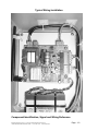
1
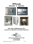
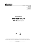
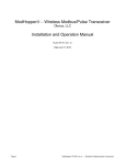
RFScada 2DI-4DO Long Range Spread Spectrum Bi-Directional Wireless Telemetry Unit User Manual By 120 NE DeBell Suite B, Bartlesville, OK 74006 Tel 918-335-3318 Fax 918-335-3328 RFScada User Manual Version 1.7 Copyright ©2002 Data Delivery Devices LLC 120 NE DeBell Suite B Bartlesville OK 74006 Tel 918-335-3318 FAX 918-335-3328 Page - 1 – Warranty Data Delivery Devices LLC warrants that products covered in this manual shall be free from defects in workmanship and materials, and shall conform to Data Delivery Devices published specifications or other specifications accepted by Data Delivery Devices LLC in writing for a period of one (1) year from the date of Data Delivery Devices LLC shipment. Limitation of Warranty Liability This warranty does not apply to any device that has been subject to abuse, neglect, accident or modification. Data Delivery Devices LLC sole obligation under its warranty shall be to repair, replace the product or issue a credit. Data Delivery Devices LLC warranty and remedies are exclusive and are made expressly in lieu of all other warranties expressed or implied, either in fact or by operation of law, statutory or otherwise, including warranties of merchantability and fitness for use. Data Delivery Devices LLC shall not be liable for damages due to delays in deliveries or use and shall in no event be liable for incidental or consequential damages of any kind, whether arising from contract, tort, or negligence, including but not limited to, loss of profits, loss of customers, loss of goodwill, overhead or other like damages. Limitation of Application Liability Data Delivery Devices LLC assumes the buyer to be an expert in his intended application of Data Delivery Devices LLC products. Data Delivery Devices LLC claims no special expertise in the application of its products into the buyer’s equipment. Data Delivery Devices LLC accepts no responsibility for the buyer’s selection and use of Data Delivery Devices LLC products. Buyer’s interpretation and implementation of application suggestions and recommendation by Data Delivery Devices LLC, general or specific, transmitted verbally, electronically or in writing, published or unpublished, is strictly at the buyers own risk. FCC Compliance Warning The RFScada device contains a transmitter module FCC ID:OUR9XTREAM. The transmitter module complies with part 15 of the FCC Rules. Operation is subject to the following two conditions: (1) The device may not cause harmful interference, and (2) the device must accept any interference that may cause undesired operation. FCC RF Exposure Warning In order to comply with the FCC RF exposure requirements the RFScada unit may only be used with approved antennas that have been tested with it. A minimum separation distance of 20cm must be maintained from the antenna to any nearby persons. The RFScada unit is not classified as a portable device per FCC Section 2.1093 RFScada User Manual Version 1.7 Copyright ©2002 Data Delivery Devices LLC 120 NE DeBell Suite B Bartlesville OK 74006 Tel 918-335-3318 FAX 918-335-3328 Page - 2 – Table of Contents General Safety Instructions Introduction Specifications Device Unpacking, Verification and Installation Signals, Connections and Wiring Reference Typical Applications and Installations External Antennas Sample Questions and Applications RFScada User Manual Version 1.7 Copyright ©2002 Data Delivery Devices LLC 120 NE DeBell Suite B Bartlesville OK 74006 Tel 918-335-3318 FAX 918-335-3328 4 5 6 7 11 19 23 25 Page - 3 – GENERAL SAFETY INSTRUCTIONS Warnings in this manual appear in either of two ways: 1. Danger warnings – The danger warning symbol is an exclamation mark enclosed in a triangle which precedes letters spelling the word “DANGER”. The Danger warning symbol is used to indicate situations, locations and conditions that can cause serious injury or death: DANGER 2. Caution Warnings - The caution warning symbol is an exclamation mark enclosed in a triangle which precedes letters spelling the word “CAUTION”. The Caution warning symbol is used to indicate situations and conditions that can cause operator injury and/or equipment damage: CAUTION Other warning symbols may appear along with the Danger and Caution symbol and are used to specify special hazards. These warnings describe particular areas where special care and/or procedures are required in order to prevent serious injury and possible death. Electrical Warnings – The electrical warning symbol is a lightning bolt mark enclosed in a triangle. The electrical warning symbol is used to indicate high voltage locations and conditions that may cause serious injury or death if proper precautions are not observed: For the purposes of this manual and product labels, a Qualified Person is one who is familiar with the installation, construction, operation and maintenance of the equipment and the hazards involved. This person must: 1. Carefully read and understand the entire manual. 2. Be trained and authorized to safely energize, deenergize, clear faults, ground, lockout and tag circuits and equipment in accordance with established safety practices. 3. Be trained in the proper care and use of protective equipment such as safety shoes, rubber gloves, hard hats, safety glasses, face shields etc. in accordance with established safety practices. 4. Be trained in rendering first aid. RFScada User Manual Version 1.7 Copyright ©2002 Data Delivery Devices LLC 120 NE DeBell Suite B Bartlesville OK 74006 Tel 918-335-3318 FAX 918-335-3328 Page - 4 – Introduction A pair of RFScada units provide a complete, high reliability, long range, spread spectrum, bi-directional wireless transmission and reception interface that allows remote monitoring and control of discrete signals. The states of contact or logic level inputs at each unit are replicated by corresponding relay contacts at the opposite units. The RFScada system has many applications in the SCADA, oil, gas, water, security and other industrial fields. The many features include..... Extremely high reliability, with oil field proven industrial grade components throughout. Highest data integrity, very secure and extensive error rejecting data communication methods to prevent the possibility of false signals. High speed, fully bi-directional and continuous signal exchange ensures each unit is capable of controlling, monitoring and verifying signals at the other unit – continuous, positive verification of correct operation. Out of the box ‘Plug and Play’ operation, no user programming, configuration or adjustments required. Duplicate a remote relay or switch without any connecting ‘wires’. All units revert to a known state upon failure or communication loss, either local or remote, within seconds. Additional outputs indicate the state of the opposite units AC power and verified communication status. Built in dual power supply options (115 VAC or 12 to 18 Volts DC) plus internal 6hour full function power fail capability, for highest system reliability. Quickly and easily add wireless I/O to existing systems; compatible with virtually all SCADA systems. Long range of up to 25 miles with an external antenna. Using the standard, enclosed antenna has a range up to 5 miles. Completely prepackaged solution in a corrosion resistant, NEMA 4X enclosure ready to be installed in virtually any location, requires just power and signal connection for operation. Most applications will not require an external antenna. No license required for ownership or operation in the USA. RFScada User Manual Version 1.7 Copyright ©2002 Data Delivery Devices LLC 120 NE DeBell Suite B Bartlesville OK 74006 Tel 918-335-3318 FAX 918-335-3328 Page - 5 – RFScada Specifications Due to continual improvements all published specifications are subject to change AC Operating voltage (note 1) DC Operating voltage (note 1) AC Power consumption DC Power consumption On board AC input fuse rating AC Input transient protection Enclosure rating Enclosure type Enclosure door closure types Dimensions Weight Temperature rating (note 2) Humidity Minimum telemetry update rate Transmission method Operating frequency RF data encryption method Signal data encryption method Internal antenna supplied Range with internal antenna Range with external antenna License required FCC approved AC power state transmitted Input signal channels transmitted Input channel signal type Input signal voltage required Input signal transient protection Input signal status indication Input signal cable length Input signal de-bounce time Input signal (transmission) status Output (received) signal channels Output (received) status channels Output (received) signal contact ratings Output (received) status contact ratings Output (received) signal indication Output (received) AC line indication Output (received) Comm indication Output (received) data status Output (received) data response time Output (received) AC fail response time Output (received) Comm fail response time Output (received) data hold time Power fail protection Internal backup battery life Power fail operation time (note 3) 115 VAC +/- 10% 48 – 62Hz 10 to 18 Volts DC <0.5 Amp < 0.25 Amp 2 Amp 115 VAC Yes, 10,000A 120 Joule MOV on board UL 508, CSA and NEMA 1,2,3,4,4X,12, 13 IEC 529, IP66 Fiberglass with stainless steel hardware Lockable snap latch or screw close available 11.75 H x 11.75 W x 6.75 D inches 8.5 Pounds -20°C to +70 °C 15-95% non-condensing 4 times per second (bi-directional) Bi-directional spread spectrum frequency hopping 902-928 MHz ISM band Proprietary 16 bit cyclic redundancy checking with 25 channel hopping Proprietary rolling code plus 16 bit cyclic redundancy check Yes, 2.1 dB Gain omni-directional half wave dipole Up to 5 miles Up to 20 miles None (USA) Yes Yes 2, plus AC line condition and communication OK state Low voltage (5V) contacts or logic level None Yes, 1500W MOV’s, surge and RF filters Yes, on board LED’s, one per channel, post de-bounce. Maximum 250 feet Approximately 0.25 second Yes, on board LED indicates each data transmission 2 2, one for other units AC power state, one for communications OK SPDT 0.5 Amp at 115 VAC, 1 Amp at 30 VDC SPST 0.5 Amp at 115 VAC, 1 Amp at 30 VDC Yes, 2 on board LED’s, one per channel, show true relay state Yes, on board LED shows AC condition at opposite unit. Yes, on board LED shows correct communication link. Yes, on board LED indicates each CRC verified data reception <0.5 second (includes transmitter input signal de-bounce time) <1 second <3 seconds Present state maintained for 5 seconds after received signal loss Yes, internal 1.2 Amp / hour sealed lead acid battery 2 - 5 Years continuous operation Minimum 6 hours Notes: 1. The unit may be powered from either a 115 VAC source or an external DC source, or a combination of both to allow fully functional and continuous operation in the event of either external power source failing. If an external 12 Volt DC source is not used the units internal 12 Volt DC backup power battery will be charged while AC power is available and will operate the unit when AC power fails. The internal backup battery requires an external supply of at least 13 Volts DC to remain charged if the AC power is not present. See the manual for full power source capabilities. 2. May be increased to 80 °C if the internal battery is not used. 3. This time will depend on which signals are active and will typically be from 8 to 12 hours. If an external 12 Volts DC supply is used the time will depend on that supplies capacity (unit draws approx. 150 mA at 12 Volts DC). RFScada User Manual Version 1.7 Copyright ©2002 Data Delivery Devices LLC 120 NE DeBell Suite B Bartlesville OK 74006 Tel 918-335-3318 FAX 918-335-3328 Page - 6 – RFScada User Manual Version 1.7 Copyright ©2002 Data Delivery Devices LLC 120 NE DeBell Suite B Bartlesville OK 74006 Tel 918-335-3318 FAX 918-335-3328 Page - 7 – Device Unpacking, Verification and Installation. Unpacking: First carefully unpack the units and verify all the contents are complete, intact and match the items ordered. If there is any discrepancy then please contact Data Delivery Devices LLC for assistance. Standard Contents (for one RFScada unit) Qty. Description 1 RFScada device (may be either screw close or lockable latch door closing type) 4 Stainless steel mounting lugs. 4 Stainless steel lug screws. 1 User Manual. 1 Test AC power cord with 3 conductor Phoenix connector 2 4-conductor Phoenix connector (for input signals and output status signals) 1 2-conductor Phoenix connector (for 12 Volt DC external power) 1 6-conductor Phoenix connector (for output signals). 1 0.125”–0.250” Cable entry flange. (May already be installed on the RFScada unit) 1 0.250”–0.375” Cable entry flange. (May already be installed on the RFScada unit) 8 TyWraps 2 1.25” 2 Amp 250 V fuses (spare). Device Verification: This procedure will allow the operator to verify the units are functioning correctly and will support the required range before permanently installing the units. It usually does not require connecting to external power or connecting to any signals. This is an easy and quick method to do in the field that does not need any special tools - it does not even require external power. Open a unit, verify it has not been damaged and there are no loose components in the housing. The RFScada units are shipped with fully charged batteries, but the batteries are disconnected from the main circuit board before shipping to prevent them from draining during shipment. Locate and connect the free plug P6 that is on the end of the battery cable into the corresponding connector J6 on the board. Like all the board connectors they will only mate one way, so to prevent damage do not try to force it if it does not appear to fit. Once it is correctly seated the status LED’s on the board should briefly flash as the device completes a self-test and initialization, then the unit should commence operation. If this does not occur possibly the battery is discharged, and the AC test lead may need to be used. RFScada User Manual Version 1.7 Copyright ©2002 Data Delivery Devices LLC 120 NE DeBell Suite B Bartlesville OK 74006 Tel 918-335-3318 FAX 918-335-3328 Page - 8 – DANGER Possibly lethal line voltages will be present on the unit’s circuit board when connected to AC line power. Before attempting to gain access, test or modify connections refer to a qualified electrician for assistance, instructions on safe operation and to ensure that connections meet all applicable safety procedures, standards and codes. To use AC power the test lead must be connected first to the 3-pin connector J1 on the unit, then plugged into an AC power source. Besides operating the unit this will also charge the battery. The operation of the relays plus the status indicators will depend on whether another matched RFScada device is running and within range. If the device is not communicating with another unit then the green ‘Transmit’ LED will briefly flash approximately twice a second. This LED illuminates each time the device transmits data, and indicates that the device is trying to establish communications with another unit. If the ‘Transmit’ LED flashes quicker than this (approximately 3 to 10 times per second) without the receive data LED illuminating it indicates that the device is either detecting corrupted data or interference from another source (probably two similar paired units which are within range, are communicating with each other and have the same ‘identity’ as this one). If the ‘Transmit’ LED flashes followed by the ‘Receive’ LED flashing in rapid succession (normal operation) then this device is successfully communicating with another device that has the same identity. For this to occur the main board, including the transmitters and receivers on each unit must all be operating correctly. Repeat the above procedure with the second unit, and they should then be in constant communication with each other, the ‘Transmit’ and ‘Receive’ LED’s on each unit should be rapidly flashing. The ‘Comms OK’ LED should also be illuminated, and the corresponding relay will also be activated. Note that units are usually ordered in pairs, if you have more than 2 units in the order ensure that a matching ‘pair’ are being tested together (they should have the same identity set, A to G, marked on the label inside the door). Once the pair of units are communicating connect a short piece of wire between terminals 1 and 2 of a Phoenix four pin plug P3. Plug this four conductor plug into the corresponding connector (J3) on one of the devices, after a very short delay (less than 0.25 second) the ’local status’ green LED by the connector should illuminate, this provides local indication showing the state of the input. Almost immediately a relay click should be heard from the other device, and the corresponding ‘output’ indicating LED will become illuminated on the other device by the relay just activated. This verifies that the input status on one device activates the ‘output’ relay on the remote device. If required, this procedure may be repeated for both input channels on both units. Once the basic device functionality has been completed the devices may be moved to the final location for range verification. If it will be some time before the range verification may be undertaken unplug the battery cable plus P6 to prevent the batteries from becoming discharged. With the devices operating temporarily locate the first unit at RFScada User Manual Version 1.7 Copyright ©2002 Data Delivery Devices LLC 120 NE DeBell Suite B Bartlesville OK 74006 Tel 918-335-3318 FAX 918-335-3328 Page - 9 – its desired position and move the second unit towards its final location. By watching the ‘Comms OK’ LED on either unit, or the transmit and receive LED’s the range may be verified. Remember that the ‘Comms OK’ LED will only illuminate if both units are communicating correctly with a continuous, full, complete and verified data exchange. The state of the inputs and outputs has no bearing on the range, and the state of the inputs does not matter to test the range. Providing the batteries are not completely discharged the range is the same whether the units operate from AC or DC power. If the required range cannot be achieved see the section on troubleshooting to resolve the problem. After the device and range verification have been completed the devices may be permanently installed. Device Installation: Establish a route and entry point for both the power and signal cables to enter the cabinet. Generally the best entry point is on the bottom side of the cabinet to minimize the possibility of cable damage. CAUTION DANGER Some manufacturers of the sealed, rechargeable batteries that may be used in the RFScada unit do not recommend charging the batteries in a hermetically sealed enclosure. Although the batteries themselves are completely sealed and may be operated at any angle it may be possible, under a certain set of rare circumstances for the battery to vent gas into the cabinet. This gas could potentially create an explosion if subsequently ignited by a spark. The battery could possibly vent gas if the charging circuit malfunctioned, the protective current-limiting fuse shorted out, the battery became severally overcharged and failed. The RFScada unit has a suitable vent in the base of the cabinet, which will allow any gas to safely vent in the event of these failures. If the internal battery is not required the vent may easily be removed and the hole may be used for cable access, since it is the same size as the cable entry fittings supplied. Mount the cabinet using the four stainless steel screws and lugs provided in the kit, use type 222 Loctite applied to the screw threads if the cabinet is to be mounted in a location subject to vibration. Since the cable entry point is often not known until RFScada User Manual Version 1.7 Copyright ©2002 Data Delivery Devices LLC 120 NE DeBell Suite B Bartlesville OK 74006 Tel 918-335-3318 FAX 918-335-3328 Page - 10 – installation, the cabinets may be supplied without any holes and the customer may drill the cabinet then install the cable clamps in a suitable position. Use caution when drilling the cabinet and always ensure that any power is removed from the device beforehand, otherwise damage to the device and serious injury may occur. Before drilling the cabinet it is usually best to remove the main internal panel that holds the circuit board, battery and internal antenna to prevent damage to the device. To do this carefully remove the 4 stainless steel screws that mount the main panel to the cabinet. Use caution removing these since the screw threads have been treated with low strength thread locker to prevent coming loose from vibration. NOTE Be especially careful by the antenna, it is securely located to both the board via a precision connector and to the panel via a non metallic stand, do not attempt to lift the panel by the antenna since damage to the main board and antenna will result. Once the panel has been removed from the cabinet, drill holes large enough (commonly available ‘step’ drills are very useful for these size holes) for the cable clamps or conduit fittings and install the clamps tightly. Remove any dust or particles remaining from drilling, then replace the panel in the cabinet and complete wiring of the inputs, outputs and power to the device. Secure power and signal cables to the inside of the case using Ty-Wraps included with the unit. Close the front door and secure with a suitable padlock (latch close version) or by tightening the door closing screws (screw close version). DANGER Possibly lethal line voltages will be present on the unit’s circuit board when connected to AC line power. Before attempting to gain access, test or modify connections refer to a qualified electrician for assistance, instructions on safe operation and to ensure that connections meet all applicable safety procedures, standards and codes. The front door should always be securely closed either by using a suitable padlock (latch close version) or by tightening the door closing screws (screw close version) to prevent access by unauthorized personnel. Apply power to the unit and verify correct operation. RFScada User Manual Version 1.7 Copyright ©2002 Data Delivery Devices LLC 120 NE DeBell Suite B Bartlesville OK 74006 Tel 918-335-3318 FAX 918-335-3328 Page - 11 – Typical Wiring Installation Component Identification, Signal and Wiring Reference. RFScada User Manual Version 1.7 Copyright ©2002 Data Delivery Devices LLC 120 NE DeBell Suite B Bartlesville OK 74006 Tel 918-335-3318 FAX 918-335-3328 Page - 12 – Component Identification This diagram identifies components, connectors and LED’s on the RFScada board assembly. Refer to the following chart and detailed notes for an explanation of items identified. RFScada User Manual Version 1.7 Copyright ©2002 Data Delivery Devices LLC 120 NE DeBell Suite B Bartlesville OK 74006 Tel 918-335-3318 FAX 918-335-3328 Page - 13 – Connector J1 J1 J1 J2 J2 J3 J3 J3 J3 J4 J4 J4 J4 J4 J4 J5 J5 J5 J5 J6 J6 Pin 1 2 3 1 2 1 2 3 4 1 2 3 4 5 6 1 2 3 4 1 2 Function 117 VAC Line Hot AC power in Ground In 117 VAC Line Neutral AC power in External 12 Volt DC input positive External 12 Volt DC input negative (connected to ground) Local contact input One (5 Volt DC via 1 K Ohm pull up resistor) Local contact input One (connected to ground) Local contact input Two (5 Volt DC via 1 K Ohm pull up resistor) Local contact input Two (connected to ground) Remote relay one contact normally closed Remote relay one contact common Remote relay one contact normally open Remote relay two contact normally closed Remote relay two contact common Remote relay two contact normally open Remote AC relay status contact Remote AC relay status contact Comms OK status relay contact Comms OK status relay contact 12 Volt battery Positive 12 Volt Battery Negative (connected to ground) All signals are identified by the preceding diagram and chart. Note that not all the connections need to be used; these will vary depending on the application. J1, AC Line Input This is 115 VAC line power and ground connection to the unit. CAUTION The non-metallic enclosure does not provide grounding from any conduit connections. Use grounding type bushings and jumper wires if metal conduit is used. If the RFScada unit is operating from an external DC supply this connecter may not be used. J2, External 12 Volt DC Input This is the low voltage input power connector, and if used is connected to a 10 to 18 Volts DC external power source (NOT the backup battery in the RFScada case). Note that pin 2 is connected to ground on the circuit board and is common to all the other RFScada User Manual Version 1.7 Copyright ©2002 Data Delivery Devices LLC 120 NE DeBell Suite B Bartlesville OK 74006 Tel 918-335-3318 FAX 918-335-3328 Page - 14 – pins that connect to ground. If an external ground is not connected via the 115 VAC power connector (J1), then an external ground should be connected to this pin. CAUTION The non-metallic enclosure does not provide grounding from any conduit connections. Use grounding type bushings and jumper wires if metal conduit is used. J3, Local Contact Inputs The switch contacts whose status is to be transmitted to the opposite unit are connected here. Shorting together pins 1 and 2 on J3 will cause the output relay one at the remote RFScada unit to activate; shorting together pins 3 and 4 on J3 will cause the output relay two at the remote RFScada unit to activate. Pins 1 &3 are both connected to 5 volts DC via a 1 K Ohm pull up resistor; pins 2 & 4 are connected to ground. An external set of dry contacts will short the inputs to activate the signals, alternatively an external open collector transistor may also be used to activate the signal is required. In this case the external transistor would need to be able to sink 5 mA. Under no circumstances should any external voltage be applied to the pins on J3. Local Input Status LED’s These two green LED’s indicate the present status of each local input at J3. They are illuminated when the external input contacts are closed and the signal de-bounce delay time has completed, so these LED’s will respond just after changes in the input signals have occurred. J4, Remote Relay Contacts J4 is connected to the contacts of two independent single-pole double-throw relays, which respond to signals applied at the other RFScada unit. Relay one contacts are activated in response to the switch contacts at the other RFScada unit input one, and relay two contacts respond to the switch contacts at the other RFScada unit input two. Each relay contact is rated at 0.5 Amp 115 VAC, or 1 Amp at 30 V DC. If loads greater than this are to be controlled a suitable larger capacity relay should be driven from this one. The common, normally open and normally closed contacts for each relay are all available at connector J4, but if possible the user should configure the system to use ‘normally open’ type configuration to ensure failsafe operation. Then in the event of a signal wire being damaged, communication signal loss or other failure a suitable alarm or course of action may be undertaken. Remote Relay Status LED’s These two red LED’s indicate the present status of each remote relay (connected to J4). They are illuminated when the relays are activated, ie the normally open contacts are closed. These LED’s are driven form a spare set of contacts on each relay, so they indicate the actual present status of the two relays. J5, Remote Status Output Contacts RFScada User Manual Version 1.7 Copyright ©2002 Data Delivery Devices LLC 120 NE DeBell Suite B Bartlesville OK 74006 Tel 918-335-3318 FAX 918-335-3328 Page - 15 – J5 is connected to the contacts of two independent single-pole single-throw relays, which respond to signals at the other RFScada unit. Pins 1 & 2 will be shorted together by the relay contacts whenever AC line power is powering the other RFScada unit, when AC power is not powering the other unit the relay contacts will open. The contacts will close when the AC voltage is above approximately 95 VAC and open when it is below about 90 VAC. If the other unit is being powered by an external 12 Volt DC source the contacts will be open. Pins 3 & 4 are connected to another set of relay contacts, which are activated when good, verified communications are in process between this RFScada unit and the other RFScada unit. The contacts will open within a few seconds when communications fail for any reason. Each relay contact is rated at 0.5 Amp 115 VAC, or 1 Amp at 30 V DC. If loads greater than this are to be controlled a suitable larger capacity relay could be driven from these. Remote Status LED’s These two yellow LED’s indicate the present status of the remote units AC power and the present state of communications between units. They are illuminated when the two relays (connected to J5) are activated, i.e. the normally open contacts are closed. These LED’s are driven from a spare set of contacts on each relay, so they indicate the actual present status of the relays. Transmit / Receive LED’s These two LED’s (red receive, green transmit) illuminate each time the unit completes a data transmission or verified data reception. Normally the two LED’s will be flashing in sequence as the unit communicates with another. If the unit is unable to receive data it will flash just the transmit LED each time it tries to establish communication. These two LED’s give a quick indication of communications, and are very useful in the case of marginal data communications or antenna adjustments. J6, Backup Battery Connector This is connected to the 12 Volt DC sealed lead acid backup battery. It supplies power to the RFScada device when AC line power or an external 12 Volt DC power supply fails; then the unit may continue to operate and draw power from the battery via this connector. Pin 1 is the positive battery connector, and pin 2 (connected to ground) goes to the negative battery connector. The board has a built in, temperature compensated, current limited float charger for the external battery. This charger is designed to safely charge the standard battery and then keep it continually charged in a ‘float’ mode. This charging circuit is protected against reverse polarity, open circuit, a dead or shorted battery, over-current in or out of the board and also has an electrically re-settable fuse. Under no circumstances should any other voltage or device be connected to these pins, the charging circuit is not designed to operate with any other type of battery. If an external DC voltage (such as a solar panel, car battery or charging system) is required to operate the RFScada unit, then connect the external voltage to connector J2. If the backup battery is not required remove it from the RFScada cabinet and unplug the connector P6 from connector J6. RFScada User Manual Version 1.7 Copyright ©2002 Data Delivery Devices LLC 120 NE DeBell Suite B Bartlesville OK 74006 Tel 918-335-3318 FAX 918-335-3328 Page - 16 – Antenna Connector The internal antenna is normally attached to this connector. If another antenna needs to be used then the internal antenna should be carefully disconnected and removed. See the section on external antennas for more details. F1, AC Power Fuse A user replaceable fuse and a transient arresting MOV protect the board. The fuse will blow if there is a malfunction in the circuit, or a voltage greater than the board rating is applied to the AC line input. The fuse is located underneath a safety cover, which in turn is secured by a Ty-Wrap. To test and replace the fuse proceed as follows: DANGER Possibly lethal line voltages will be present on the unit’s circuit board when connected to AC line power. Before attempting to gain access, test or modify connections refer to a qualified electrician for assistance, instructions on safe operation and to ensure that connections meet all applicable safety procedures, standards and codes. First remove all AC power to the unit. Cut and remove the Ty-Wrap that secures the fuse safety cover. Remove the safety cover. Using an Ohm Meter measure the resistance of the fuse, if the resistance is high or infinite the fuse has failed and needs to be replaced. If it has failed discard and replace with a spare 2 Amp 250 V that is supplied with the unit. Do not use a fuse with any other rating. Replace the fuse safety cover and secure with a Ty-Wrap included with the unit. To check the fuse and AC operation the 12 Volt battery cable plug P6 may be unplugged from connector J6 before re-applying AC line voltage. If the unit does not power up correctly please contact Data Delivery Devices LLC for assistance. Once correct operation has been verified the battery (if installed) should be re-connected. Battery Maintenance and Replacement. The standard 12 Volt DC 1.2 Amp / hr battery has a limited lifetime, typically between 2 to 5 years but it will vary depending on the environment and type of use. NOTE The battery life will be severely limited if it is left in a completely discharged state. If the RFScada unit is not going to be used for some time and will not have AC power applied then unplug the battery cable plug P6 to prevent the battery from becoming completely discharged. The battery will continue to maintain a charge for a year or more without requiring charging provided there is no load, so unplug it if the unit will not be used. RFScada User Manual Version 1.7 Copyright ©2002 Data Delivery Devices LLC 120 NE DeBell Suite B Bartlesville OK 74006 Tel 918-335-3318 FAX 918-335-3328 Page - 17 – The battery condition may be verified periodically by simply removing the normal source of power (AC line or low voltage DC). The RFScada unit should continue to operate for at least 6 hours, if it does not then replace the battery. Acceptable replacement types are Power-Sonic PS-1212 or Panasonic LC-R121R3PU. To replace the battery proceed as follows: CAUTION DANGER Some manufacturers of the sealed, rechargeable batteries that may be used in the RFScada unit do not recommend charging the batteries in a hermetically sealed enclosure. Although the batteries themselves are completely sealed and may be operated at any angle it may be possible, under a certain set of rare circumstances for the battery to vent gas into the cabinet. This gas could potentially create an explosion if subsequently ignited by a spark. The battery could possibly vent gas if the charging circuit malfunctioned, the protective current-limiting fuse shorted out, the battery became severally overcharged and failed. The RFScada unit has a suitable vent in the base of the cabinet, which will allow any gas to safely vent in the event of these failures. If the internal battery is not required the vent may easily be removed and the hole may be used for cable access, since it is the same size as the cable entry fittings supplied. DANGER Possibly lethal line voltages will be present on the unit’s circuit board when connected to AC line power. Before attempting to gain access, test or modify connections refer to a qualified electrician for assistance, instructions on safe operation and to ensure that connections meet all applicable safety procedures, standards and codes. RFScada User Manual Version 1.7 Copyright ©2002 Data Delivery Devices LLC 120 NE DeBell Suite B Bartlesville OK 74006 Tel 918-335-3318 FAX 918-335-3328 Page - 18 – First remove all AC power to the unit. Unplug the battery cable plug P6 from the board connector J6. Cut and remove Ty-Wrap’s that secure the battery. Carefully pull the old battery away from the panel. Unplug the cable terminals from the old battery, and plug them onto the new battery making sure they are connected red wire to positive (+) on the battery and black wire to negative (-) on the battery. Locate the new battery in position and secure it with three new Ty-Wraps supplied with the replacement battery. Plug the battery cable plug P6 into connector J6 on the board. Return the unit to service and re-apply AC power. After the unit has been back in service for a few hours remove AC power and verify correct operation using the new battery, if it does not operate correctly contact Data Delivery Devices LLC for assistance. RFScada User Manual Version 1.7 Copyright ©2002 Data Delivery Devices LLC 120 NE DeBell Suite B Bartlesville OK 74006 Tel 918-335-3318 FAX 918-335-3328 Page - 19 – Typical Applications and Installations. Fluid Monitoring / Control Remotely monitor both high and low levels of a tank and control the fill / drain pumps from 20 miles away without interconnecting wires. The RFScada devices also provide automatic local and remote alarms for power or system failures, plus full function operation for hours due to the standard built in battery backup. RFScada User Manual Version 1.7 Copyright ©2002 Data Delivery Devices LLC 120 NE DeBell Suite B Bartlesville OK 74006 Tel 918-335-3318 FAX 918-335-3328 Page - 20 – VSD / VFD Control. A variable speed drive may be controlled at a distance using the RFScada units. Depending on the type of drive, the speed may be raised or lowered and other features may be operated. The RFScada units provide automatic shutdown in the case of any system or communication failures. RFScada User Manual Version 1.7 Copyright ©2002 Data Delivery Devices LLC 120 NE DeBell Suite B Bartlesville OK 74006 Tel 918-335-3318 FAX 918-335-3328 Page - 21 – Access Control / Monitoring Here a pair of wireless RFScada units remotely protect, monitor and control access to a secure location up to 20 miles away. Alarms are activated whenever access is required or gained. The electrical lock may be controlled remotely as well as locally. Remote indication is supplied to show if the door is securely closed, when it is opened plus full visual status of conditions. Alarms indicate all faults and abnormal conditions, such as power fail or forced entry. RFScada User Manual Version 1.7 Copyright ©2002 Data Delivery Devices LLC 120 NE DeBell Suite B Bartlesville OK 74006 Tel 918-335-3318 FAX 918-335-3328 Page - 22 – Security / Environmental Systems From up to 20 miles, without interconnecting wires the RFScada units can control and continuously monitor environmental systems such as pumps, fountains, heaters and security devices. Alarms are activated to indicate any fault conditions, and battery backup provides full operation during power failures. RFScada User Manual Version 1.7 Copyright ©2002 Data Delivery Devices LLC 120 NE DeBell Suite B Bartlesville OK 74006 Tel 918-335-3318 FAX 918-335-3328 Page - 23 – External Antennas. In some situations, due to distance, obstacles or other factors an external antenna may need to be installed on one or possibly both units. If in doubt two antennas may be ordered, then one returned for credit if not required. Two FCC approved Yagi type antennas (9 dB and 12 dB gain) are offered for operation with the device. Also supplied with the antenna is a suitable cable, with a special ‘reverse polarity’ SMA plug to attach to the antenna connector on the RFScada board. At the other end of the cable is a weatherproof ‘N’ type connector that connects to the antenna. A weatherproof cable entry clamp is also installed on the cable, so it may be mounted in a suitable hole drilled in the case. The length of cable needs to be specified when ordering, bear in mind that signal loss due to the cable will be approximately 1.5 dB per 10 feet, so limit the cable length to the minimum required. The total installed cost of antennas including the cable, pole (if needed), time and labor required etc. is often not significant between the 9 dB and 12 dB antennas, so generally the higher gain antenna is recommended. There is also a better chance that the higher gain antenna will give satisfactory performance without requiring an external antenna on the other unit. An excellent source of technical information concerning the antennas, radiation patterns, selection criteria, features etc. may be found online at http://www.astronantennas.com/framed_library.html RFScada User Manual Version 1.7 Copyright ©2002 Data Delivery Devices LLC 120 NE DeBell Suite B Bartlesville OK 74006 Tel 918-335-3318 FAX 918-335-3328 Page - 24 – FCC RF Exposure Warning In order to comply with the FCC RF exposure requirements the RFScada unit may only be used with approved antennas that have been tested with it. A minimum separation distance of 20cm must be maintained from the antenna to any nearby persons. The RFScada unit is not classified as a portable device per FCC Section 2.1093 RFScada User Manual Version 1.7 Copyright ©2002 Data Delivery Devices LLC 120 NE DeBell Suite B Bartlesville OK 74006 Tel 918-335-3318 FAX 918-335-3328 Page - 25 – Sample Questions and Applications. 900 MHz vs 2.4 GHz It seems that everywhere you look another ‘spread spectrum’ 2.4GHz devices comes out, including cordless phones, local wireless computer networks for homes and offices, video cameras, video links etc. Isn’t the very popular 2.4GHz frequency band the way to go, a quick survey shows almost everything wireless in Wal-Mart’s electronics department to be a 2.4 GHz device. For a long range, high reliability product such as the RFScada device the 2.4 GHz band is not the best choice. For short range (typically less than a hundred feet), generally indoor, high bandwidth devices such as video links or wireless computer networks the 2.4 GHz band has some advantages, such as using a smaller antenna than required by 900 MHz devices. Many public places like airline terminals, hotels, hospitals, coffee houses, bookstores etc. are installing these wireless networks, and so the band has quickly become saturated with these devices, especially in urban locations. This often results in interference and poor (or no) operation for devices that compete in this frequency range; many users are now finding that additional 2.4GHz devices will not operate satisfactorily in the vicinity of other 2.4 GHz devices. An additional advantage of the 900 MHz band is the greater range (typically 3 times that of 2.4GHz) and reduced attenuation from rain when compared to 2.4GHz devices. The 900 MHz band is the best choice for devices such as the RFScada products, which are designed for the highest reliability, interference rejection and longest range in hostile environments. Cordless Phone I have a ‘spread spectrum’ cordless phone at the house, it has trouble operating more than 100 feet from the base station and it certainly does not work ¼ mile away. I understand that the RFScada is also a ‘spread spectrum’ device, how can it operate 1, 5 or even 20 miles away? The main reason is power. The term ‘spread spectrum’ covers a general method of transmission, where transmit and receive frequencies are constantly changing or ‘hopping’ through various channels. This method was devised as a means to allow many devices to effectively share a bandwidth. There are several classifications allowed by the FCC to cover different devices and applications, these classifications also govern both the RF power and antenna systems that may be used. These classifications all use the generic term ’spread spectrum’ as a transmission method. The FCC designates your cordless phone and similar consumer devices as a ‘portable device’ with a severely limited RF power output and antenna. The RFScada is not designated in this group, and therefore may transmit both with a higher power plus it may also use an FCC approved directional antenna that provides more system power gain in certain directions. In fact, because of the higher RF power output emitted by the RFScada unit the FCC mandates that it must maintain a separation distance of at least 20 cm (about 8 inches) to any nearby persons. True Range The range is mentioned as 0.25, 5 and 20 miles etc. What is the real range? This is a very difficult question to answer, since it will vary in every installation. The actual range will depend on many factors, including the device location, height, shape of RFScada User Manual Version 1.7 Copyright ©2002 Data Delivery Devices LLC 120 NE DeBell Suite B Bartlesville OK 74006 Tel 918-335-3318 FAX 918-335-3328 Page - 26 – the terrain, terrain surface, obstacles, the antenna used, proximity to similar devices etc. As a very general guideline in a typical, outdoor location where each RFScada unit may be visible from the other and using the internal antennas supplied with the standard product a range of at least two miles is to be expected, and five miles is usually possible. A similar ‘line of sight’ installation, using the optional 12 dB gain Yagi antennas at each end should produce a range of 25 miles. Using the internal antenna and inside a typical factory, with moving and stationary machines, obstacles, metal walls, interfering devices and no line of sight the range may be reduced to a few hundred yards. If one unit were to be located inside a 2 inch thick lead box then (just like any other RF transmitter and receiver) the range will be reduced to zero. The range depends on many factors. Please see the product manual for a full discussion of factors that may affect the range. If you are unsure of the performance for your application please inquire about the availability of evaluation units for testing at your location. Separate Transmitter and Receiver. I ordered a transmitter for my tank and receiver for the well control. There appears to have been a mistake as both units look to be identical. Shouldn’t one be a transmitter and one a receiver? They are identical; each unit is both a transmitter and a receiver. This is the only way that units are able to positively verify correct operation of the other unit. Whatever the states of the ‘input contacts’ are at one unit will be reflected at the ‘output contacts’ states at the other unit. The units continually communicate with each other to ensure constant and valid data exchange. If for some reason a unit needs to be replaced (for instance it may be been damaged or stolen) then another standard unit may replace it. System Data Verification How do I know that the output data I receive is valid and is not interference from another device? There are many levels of sophisticated data encryption and protection incorporated in the device. Lets follow a typical signal to see what actually happens. First of all the ‘input data’ (input contacts) at the transmitter must be stable for a minimum period of time before the signal is processed. This can be seen by the brief (approx. quarter second) ‘de-bounce’ time delay between the input signal changing state and the transmitting data ‘input status’ indicator LED reflecting the change. This delay allows the input signal to stabilize, removes any spurious noise that may be on the input signal and it prevents possible relay ‘chatter’ at the other unit due to an intermittent input signal. Once the input signal is stable it is encrypted in a data format that incorporates a constantly changing rolling code and is then mixed with other data pertinent to the unit, such as the local AC power status. A 16-bit cyclic redundancy check (CRC) value is then calculated for this coded data and added. Now the encrypted plus CRC coded data is passed to the RF section and transmitted using 25 constantly changing frequencies and using yet another, completely independent 16-bit CRC with a different algorithm from the first. The remote unit receives the RF data and verifies that the 16-bit RF CRC is correct. It then further analyzes the received data and verifies that it also passes the second CRC encryption check. The transmitted ‘input data’ plus other information from the first unit is then removed from this dual-verified data. Finally this data is used to update the state of the outputs, to faithfully reflect the input state of the first unit. Any ‘single bit’ error in the whole process will result in an unverified data packet, and that data will be RFScada User Manual Version 1.7 Copyright ©2002 Data Delivery Devices LLC 120 NE DeBell Suite B Bartlesville OK 74006 Tel 918-335-3318 FAX 918-335-3328 Page - 27 – completely ignored. If ‘correct and double verified’ data does not arrive at a receiver for about 2 seconds the unit will extinguish the ‘COMMS OK’ status LED and set the ‘COMMS OK’ relay output to inactive, ie its normally open contacts will open. If ‘correct and double verified’ data does not arrive at a receiver for about 5 seconds all the outputs will change to the default output state, where each output relay will revert to the ‘inactive state’, in other words the normally closed contacts will become closed and the normally open contacts will open. After good data has been received at one unit it will repeat the whole process by transmitting its own input states to the other unit in a similar manner. Each unit will complete the whole cycle (input/encrypt, transmit data, receive data, decrypt, update outputs) several times a second to insure that the output data is valid. If either unit fails for any reason the maximum time before all outputs change (on both units) to the ‘default’ state will be 5 seconds. Failures or Damage to the System. What happens if one box fails or is vandalized?. If either unit fails or communication is disrupted for any reason the maximum time before the outputs change to the ‘default’ state will be 5 seconds. The outputs on both units will change to the default state, regardless of which unit failed. Functional Integrity and Verification We want to replace some competitors units that have poor range and marginal performance. Also, since we now realize the competitors units we own are just ‘one way’ devices we have actually been using two complete sets of them for each signal monitored, as we need to verify that they are actually functioning - data integrity is very important for this application. With the RFScada units is there a way to tell if the remote unit is receiving my signal correctly? Yes, there is full data verification. Unlike competitors ‘one way’ or ‘report on an event’ type these maintain continuous communication and are fully bi-directional so there are several ways to verify full and correct data transfer. Since both units are identical with built in transmitters and receivers it is easy to verify reception of data remotely. First of all, by the very nature of the device if the two on board transmit and receive status LED’s are quickly flashing (normal operation) the devices are both exchanging good, verified data. Secondly, the normally open, ‘Communication OK’ contacts (connector J5 pins 3 and 4) will be closed all the time that the devices are maintaining a verified data exchange; and the ‘COMMS OK’ status LED will also be illuminated. When communication is interrupted, at either unit and for any reason the ‘COMMS OK’ contacts will open plus the status LED will extinguish at both units within 3 seconds of the interruption. Finally, if required it is possible to manually verify complete operation of both units. Take the second, unused output of the remote unit and directly connect it to an unused input (for example input two) on the remote unit. At the ‘base’ unit close (short together) input two. This will cause output two of the remote unit to close, which is now directly wired to input two on the remote unit. This state of input two will now be transmitted back to the ‘base’ unit by the remote. Therefore, providing both units are functioning and communicating changing the state of the ‘base’ unit input two will cause the monitored output two at the base unit to also change, all within a second. This verifies, in order, full local data input, encryption, local RF transmission, remote RF reception, remote decryption, remote output, remote input, remote encryption, remote RF transmission, local RF reception, local decryption, local verification and local output all within a second. RFScada User Manual Version 1.7 Copyright ©2002 Data Delivery Devices LLC 120 NE DeBell Suite B Bartlesville OK 74006 Tel 918-335-3318 FAX 918-335-3328 Page - 28 – AC Power Loss and Generator Operation Our remote unit is powered from a generator that automatically starts and runs for a couple of hours then stops for a few minutes. The remote unit is successfully monitoring the tank level, and continues to operate correctly when the generator is stopped, powered by its internal rechargeable battery. Is it possible to also monitor when the generator is running? Yes, this capability is built in. The normally open contacts of ‘Remote AC OK’ output (connector J4 pins 1 and 2) continually indicate the status of the remote units AC power. When the generator is running at the remote unit it will transmit this status to the ‘base’ unit and it in turn will activate (close) the ‘Remote AC OK’ contacts; the status LED will also be illuminated. It will become inactive and the LED will be extinguished when the generator (or other AC power source) stops. Interference between Multiple Units We have a pair of RFScada units that have been operating flawlessly for some time. We now need another pair but they will be located within a couple of miles from the first. Will two pairs of RFScada interfere with each other? Each pair of units is matched together for transmission and reception. There are seven sets of identity that the units may have, so up to seven pairs of units may all operate in close proximity so long as they all have different id’s. When supplied the standard units are configured for set ‘A’, but they can be configured at the factory for ‘A’ to ‘G’. A record is kept of the units supplied for each customer, so when ordering additional units please advise if you need a replacement for a damaged one or a unit to operate on a different frequency set. There are solutions offered for applications where more than seven pairs are required to operate, or systems where there is a single ‘base’ master unit and multiple slave units, please consult the factory for further details. Rain Attenuation Here in the jungle we often experience heavy rain. Does it affect operational range? Heavy rain does have an affect on the range, but it is generally negligible. It attenuates the signal by approximately 0.2dB per mile for a torrential storm, which means a range difference of less than a few feet per mile. Pampered Horses We train and stable many valuable horses for clients on a large ranch. For security reasons we have just installed an electrically operated locking gate restricting access to the property. The gate is powered by a solar panel and 12 Volt battery since it is remote from any source of power. It also came with remote controls from the manufacturer that allow us to operate it from our vehicles when we are within 50 feet or so, but they will not operate from our main office which although visible from the gate is almost a mile away. We have considered purchasing additional remotes for staff to use, but we also have many frequent visitors and deliveries. If the gate is not staffed we install a sign that advises visitors to sound their horn on arrival, whoever is closest drives down by the gate and opens it. This most undignified entry method is obviously not acceptable for us, our clients or the horses that may be startled by the noise. The gate opener has a provision for a manual switch to allow anyone to operate the gate, but we have not installed that since it defeats the purpose of having the gate for security. The only other option available is a keypad by the gate with a code to enter, but again it is not suitable RFScada User Manual Version 1.7 Copyright ©2002 Data Delivery Devices LLC 120 NE DeBell Suite B Bartlesville OK 74006 Tel 918-335-3318 FAX 918-335-3328 Page - 29 – for our many visitors. We would also like to be alerted when the gate is operated so we may monitor activity. The gate installation companies we have contacted all have just one possible solution left for us - digging a trench for over a mile around the lake and across the beautifully landscaped grounds, then installing a cable connected to the gate switch; allowing us to operate the gate from the office. This ‘solution’ would be very disruptive to our operations, very expensive, we would not know when vehicles with remotes came or left and our clients would still be sitting in their vehicles honking the horn to gain entry. Can the RFScada solve any of these problems? Yes, the RFScada can solve all of your problems. Here is how to do it. Install one unit at the office powered by the standard AC line. Connect a normally open push button switch to ‘input one’, this will be used to allow gate operation from the office. Connect an indicator light or alarm indicator such as a bell wired to use the ‘output one’ normally open contacts. Install the other (we will call it gate unit) by the gate control. The gate unit may be powered directly from the 12 volts DC supplied by the gate control battery and solar panel since its current draw is small. Connect the normally open contacts from ‘output one’ to the ‘manual operation’ switch input on the gate control. When the push button is pressed in the office the gate will operate. Now to solve the next problem, alerting office personnel when a guest arrives. A switch may be installed by the gate connected to ‘input one’ on the gate unit. When visitors arrive they may press this button, which in turn will activate the alarm at the office. When the office personnel have verified the guest’s identity they may operate the gate from the office. Rather than having guests press a button by the gate another option is to use a motion/proximity detector or ‘breaking beam’ type detector ahead of the gate connected to ‘input one’. This detector could be situated a short distance before the gate to provide an alarm at the office before the guest arrived, minimizing any delay. As an added measure of security the second unused input to the gate unit may be wired closed, or even better connected to a tamper switch or a switch active when the gate was positively locked. Due to this the office unit would have ‘output two’ active all the time under normal circumstances, so another alarm (or it could be wired in parallel with the first alarm) would be connected to the ‘output two’ normally closed contacts. If the secure, continuous data communication between the office and gate units were disrupted for any reason, including the gate battery failing, cut wires, theft, vandalism etc. then ‘output two’ at the office would change state alerting the office personnel. The RFScada provides a complete, secure and cost effective solution that adds additional benefits without requiring extensive digging, disgruntled clients or frightened horses. Medical Applications We have some medical equipment that may be able to utilize two RFScada units. Are they suitable for this for application? No, they are not. The RFScada units are not authorized nor intended for life support or medical applications. FCC License Our old SCADA system radio modem & RTU combination has failed again and we would like to replace it with two RFScada units. Do we need to convert our present FCC license to use the RFScada devices?. No need. No license is required to own or operate the RFScada devices within the USA, and the FCC already approves them. Save the renewal fees and throw away your old FCC license along with the failed SCADA system. RFScada User Manual Version 1.7 Copyright ©2002 Data Delivery Devices LLC 120 NE DeBell Suite B Bartlesville OK 74006 Tel 918-335-3318 FAX 918-335-3328 Page - 30 – Solar Panel Operation I understand that the RFScada has a 12 Volt rechargeable battery inside the case. Can I just connect a 12 volt solar panel directly to the internal battery and operate the unit without AC power? No. The internal battery has enough capacity (1.2 Amp/Hr) to operate the unit for at least 6 hours, but probably no longer than 10 hours, so it would not have enough capacity to operate the unit through the night even if fully charged. Also, many of the small, very basic solar panels have no ‘charge control’ to prevent overcharging the battery so damage could result. The very small ‘trickle’ type solar panels do not have a high enough output to operate the unit. However, the RFScada may easily be operated from a solar panel if suitable components are used. First of all a panel must be selected that can supply at least three or four times the energy required to operate the RFScada (approximately one to two watts), since the panel must both supply the unit and be capable of charging the battery in the shortest daylight available, even on a cloudy day. A system using a panel having a nominal 10 or 20 watts output should have an ample safety margin. Secondly a battery must be selected that will be able to hold enough energy to operate the RFScada for a period of time, plus the battery must be able to withstand the sometimes fairly heavy charging and discharge cycle. Small auto or marine ‘deep cycle’ type batteries are most commonly used, as they are universally available at a very reasonable cost. Finally, as mentioned earlier it is possible to damage batteries by overcharging them, so some type of charge controller is normally required. Some solar panels have the charge controller already built in, if that type of panel is used another controller is not needed. The components required will vary depending on the location, for example Alaska in winter has very little daylight available, so a solar system there would need much greater capacity than one located in Arizona. It is usually possible to connect the RFScada directly to an existing 12 Volt solar power system that is being used to power other equipment such as RTU’s or transducers, simply connect the external source to the 12V DC input (J2 pins 1 and 2). The internal backup battery is charged via a charge controller built into the RFScada unit and is not connected directly to the 12Volt DC input, so it will not be damaged by a fluctuating DC voltage being supplied to the RFScada 12Volt DC (J2) input. Do not attempt to connect an external 12 Volt source to the 12 Volt backup battery or the battery connector (J6) in the RFScada unit. Cabinet Construction The brochure states that the RFScada has a corrosion resistant NEMA 4X rated cabinet but the antenna is located inside. Doesn’t the stainless steel cabinet severely restrict the unit’s range? No, the corrosion resistant NEMA 4X rated cabinet is not stainless steel but made from fiberglass with stainless steel fittings (hinge, locking latch etc.) so it has very little effect on the signal. Mounting Inside Steel Enclosure If the unit is mounted inside a steel electrical switchboard will the range be affected? Yes, the range will be reduced if it is mounted inside a steel enclosure. Whether the attenuation will be enough to prevent operation will depend on the cabinet, distance to the other unit and all the other factors that affect range. RFScada User Manual Version 1.7 Copyright ©2002 Data Delivery Devices LLC 120 NE DeBell Suite B Bartlesville OK 74006 Tel 918-335-3318 FAX 918-335-3328 Page - 31 –