1
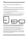
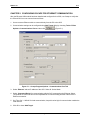
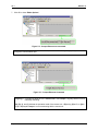
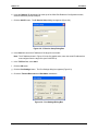
Supplement for HE-XEC XL Series Ethernet COM Module MAN0817-02 MAN0817-02 PREFACE PREFACE This manual explains how to use the XL Series Ethernet COM Module. Copyright (C) 2006 Horner APG, LLC., 59 South State Avenue, Indianapolis, Indiana 46201. All rights reserved. No part of this publication may be reproduced, transmitted, transcribed, stored in a retrieval system, or translated into any language or computer language, in any form by any means, electronic, mechanical, magnetic, optical, chemical, manual or otherwise, without the prior agreement and written permission of Horner APG, Inc. All software described in this document or media is also copyrighted material subject to the terms and conditions of the Horner Software License Agreement. Information in this document is subject to change without notice and does not represent a commitment on the part of Horner APG. Cscape, SmartStack, SmartStix and CsCAN are trademarks of Horner APG. Ethernet is a trademark of Xerox Corporation. Micro SD and CompactFlash are registered trademarks of SanDisk Corporation. MS-DOS, Microsoft, Windows 95, Windows 98, Windows 2000, Windows NT, and Windows XP are trademarks of Microsoft Corp. For user manual updates, contact Technical Support: North America: Tel: (+) (317) 916-4274 Fax: (+) (317) 639-4279 Web: www.heapg.com Email: [email protected] Europe: Tel: (+) 353-21-4321-266 Fax: (+) 353-21-4321-826 Web: www.horner-apg.com Email: [email protected] September 4, 2009 Page 3 of 24 # 986 PREFACE MAN0817-02 LIMITED WARRANTY AND LIMITATION OF LIABILITY Horner APG, LLC. ("HE-APG") warrants to the original purchaser that the XL Series Ethernet COM Module manufactured by HE-APG is free from defects in material and workmanship under normal use and service. The obligation of HE-APG under this warranty shall be limited to the repair or exchange of any part or parts which may prove defective under normal use and service within two (2) years from the date of manufacture or eighteen (18) months from the date of installation by the original purchaser whichever occurs first, such defect to be disclosed to the satisfaction of HE-APG after examination by HE-APG of the allegedly defective part or parts. THIS WARRANTY IS EXPRESSLY IN LIEU OF ALL OTHER WARRANTIES EXPRESSED OR IMPLIED INCLUDING THE WARRANTIES OF MERCHANTABILITY AND FITNESS FOR USE AND OF ALL OTHER OBLIGATIONS OR LIABILITIES AND HE-APG NEITHER ASSUMES, NOR AUTHORIZES ANY OTHER PERSON TO ASSUME FOR HE-APG, ANY OTHER LIABILITY IN CONNECTION WITH THE SALE OF THIS XLe Ethernet COM Module. THIS WARRANTY SHALL NOT APPLY TO THIS XLe Ethernet COM Module OR ANY PART THEREOF WHICH HAS BEEN SUBJECT TO ACCIDENT, NEGLIGENCE, ALTERATION, ABUSE, OR MISUSE. HE-APG MAKES NO WARRANTY WHATSOEVER IN RESPECT TO ACCESSORIES OR PARTS NOT SUPPLIED BY HE-APG. THE TERM "ORIGINAL PURCHASER", AS USED IN THIS WARRANTY, SHALL BE DEEMED TO MEAN THAT PERSON FOR WHOM THE XLe Ethernet COM Module IS ORIGINALLY INSTALLED. THIS WARRANTY SHALL APPLY ONLY WITHIN THE BOUNDARIES OF THE CONTINENTAL UNITED STATES. In no event, whether as a result of breach of contract, warranty, tort (including negligence) or otherwise, shall HEAPG or its suppliers be liable of any special, consequential, incidental or penal damages including, but not limited to, loss of profit or revenues, loss of use of the products or any associated equipment, damage to associated equipment, cost of capital, cost of substitute products, facilities, services or replacement power, down time costs, or claims of original purchaser's customers for such damages. To obtain warranty service, return the product to your distributor with a description of the problem, proof of purchase, post paid, insured and in a suitable package. ABOUT PROGRAMMING EXAMPLES Any example programs and program segments in this manual or provided on accompanying diskettes are included solely for illustrative purposes. Due to the many variables and requirements associated with any particular installation, Horner APG cannot assume responsibility or liability for actual use based on the examples and diagrams. It is the sole responsibility of the system designer utilizing the XLe Ethernet COM Module to appropriately design the end system, to appropriately integrate the XLe Ethernet COM Module and to make safety provisions for the end equipment as is usual and customary in industrial applications as defined in any codes or standards which apply. Note: The programming examples shown in this manual are for illustrative purposes only. Proper machine operation is the sole responsibility of the system integrator. September 4, 2009 Page 4 of 24 # 986 MAN0817-02 PREFACE Table of Contents LIMITED WARRANTY AND LIMITATION OF LIABILITY........................................................................... 4 CHAPTER 1 : SAFETY / COMPLIANCE .................................................................................................... 7 1.1 Safety Warnings and Guidelines .................................................................................................... 7 CHAPTER 2 : INTRODUCTION .................................................................................................................. 9 2.1 Overview......................................................................................................................................... 9 2.2 Ethernet COM Module (XEC) Option ............................................................................................. 9 CHAPTER 3 : INSTALLATION ................................................................................................................. 11 3.1 Installation Procedure (XLe OCS illustration)............................................................................... 11 CHAPTER 4 : CONFIGURATION USING THE SYSTEM MENU of the OCS .......................................... 13 4.1 Overview....................................................................................................................................... 13 4.2 Enabling and Configuring the Ethernet Port (XLe illustration)...................................................... 13 CHAPTER 5 : CONFIGURING CSCAPE FOR ETHERNET COMMUNICATION .................................... 15 APPENDIX A (use COM port Redirector only for Cscape version 8.6 and previous releases)......... 17 1 Overview .......................................................................................................................................... 17 2 Installing Com Port Redirector ......................................................................................................... 17 3 Creating Virtual COM Ports.............................................................................................................. 19 4 Configuring COM Port Redirector .................................................................................................... 20 5 Technical Support Contacts ............................................................................................................. 22 INDEX ......................................................................................................................................................... 23 TABLE OF FIGURES ................................................................................................................................. 24 September 4, 2009 Page 5 of 24 # 986 PREFACE September 4, 2009 MAN0817-02 Page 6 of 24 # 986 MAN0817-02 CH. 1 CHAPTER 1: SAFETY / COMPLIANCE 1.1 Safety Warnings and Guidelines When found on the product, the following symbols specify: Warning: Consult user documentation. Warning: Electrical Shock Hazard. WARNING: To avoid the risk of electric shock or burns, always connect the safety (or earth) ground before making any other connections. WARNING: To reduce the risk of fire, electrical shock, or physical injury it is strongly recommended to fuse the voltage measurement inputs. Be sure to locate fuses as close to the source as possible. WARNING: Replace fuse with the same type and rating to provide protection against risk of fire and shock hazards. WARNING: In the event of repeated failure, do not replace the fuse again as a repeated failure indicates a defective condition that will not clear by replacing the fuse. WARNING: Only qualified electrical personnel familiar with the construction and operation of this equipment and the hazards involved should install, adjust, operate, or service this equipment. Read and understand this manual and other applicable manuals in their entirety before proceeding. Failure to observe this precaution could result in severe bodily injury or loss of life. • • All applicable codes and standards need to be followed in the installation of this product. For I/O wiring (discrete), use the following wire type or equivalent: Belden 9918, 18 AWG or larger. Adhere to the following safety precautions whenever any type of connection is made to the module. • • • • • • • • Connect the green safety (earth) ground first before making any other connections. When connecting to electric circuits or pulse-initiating equipment, open their related breakers. Do not make connections to live power lines. Make connections to the module first; then connect to the circuit to be monitored. Route power wires in a safe manner in accordance with good practice and local codes. Wear proper personal protective equipment including safety glasses and insulated gloves when making connections to power circuits. Ensure hands, shoes, and floor are dry before making any connection to a power line. Make sure the unit is turned OFF before making connection to terminals. Make sure all circuits are de-energized before making connections. Before each use, inspect all cables for breaks or cracks in the insulation. Replace immediately if defective. September 4, 2009 Page 7 of 24 # 986 CH. 1 MAN0817-02 NOTES September 4, 2009 Page 8 of 24 # 986 MAN0817-02 CH. 2 CHAPTER 2: INTRODUCTION 2.1 Overview To supplement the built-in MJ1 and MJ2 serial ports on the XL Series, an Ethernet COM Module (XEC) can provide Ethernet communications, by installing it internal to the OCS. Note: MJ1 shares its serial port with the XEC, so when the XEC is installed and active, the MJ1 connector is inactive. Internal to the XL OCS, there is a CPU board, and up to two installed modules. Model XX000 has no installed I/O or COM modules. All other models have an I/O module in Slot 1 and can have a userinstalled COM module, such as the XEC, in Slot 2. The Ethernet COM module supports both 10 BaseT (10 Mbps) and 100 BaseTx (100 Mbps) as well as both half and full duplex communication. Both the connection speed and the duplex are auto-negotiated. 2.2 Ethernet COM Module (XEC) Option An installed Ethernet COM module allows - PC applications such as Cscape and EnvisionRV to communicate with an XL Series OCS over a LAN or over the Internet. - Horner OPC Server installed on PC, to allow other standard PC applications (database, spreadsheet programs etc.) access to OCS registers. - Modbus TCPIP protocol downloaded from http://www.heapg.com/Pages/TechSupport/Downloads.html to communicate with other Modbus TCPIP protocol supporting devices. Note: When using ‘Open’ and ‘Close’ ladder functions to start and end Modbus TCPIP communications ladder program must wait for the power flow at the output of these functions (usually it takes 10-15 seconds for the reconfiguration of the Ethernet COM module to complete). The physical connection between the Ethernet COM Module and the Local Area Network is done using a standard Ethernet cable (CAT5 or better with RJ45 modular plug). September 4, 2009 Page 9 of 24 # 986 CH. 2 MAN0817-02 Figure 2.1 illustrates a PC connected to an XLe controller over a Local Area Network. The PC can be directly connected to the XLe, using a crossover cable, or it can connect via a Local Area Network (LAN), using hubs, switches and routers. In addition, if the LAN includes a Gateway server, communication with the XLe from outside the LAN (e.g. via the Internet) can be performed. Figure 2.1 – PC to XLe Local Area Network (LAN) Connection September 4, 2009 Page 10 of 24 # 986 MAN0817-02 CH. 3 CHAPTER 3: INSTALLATION Note: Each XL Series OCS is shipped with a datasheet in the box. The datasheet is the first document that should be read for model-specific information such as pin-outs, jumper settings, and other key installation information. A User Manual is also available that provides general information that can be downloaded from our web. Visit our website (see page 22) to obtain user documentation and updates. 3.1 Installation Procedure (XLe OCS illustration) 1. Disconnect all power from the XLe unit including I/O power. 2. Remove the four screws on the back of the XLe unit and remove the back cover. The back cover can be discarded or saved, but it will be replaced with the extended back cover that ships with the XEC Ethernet COM module. Screws are re-used (Figure 3.1). REMOVE FOUR SCREWS AS SHOWN AND REMOVE BACK COVER. DISCARD BACK COVER ONLY! DO NOT DISCARD SCREWS! 001XLE058 INSTALL COM BOARD BY ALIGNING CONNECTOR AND SEATING BOARD FULLY ON STANDOFFS. INSTALL NEW BACK COVER RE-USING THE FOUR SCREWS. Figure 3.1 – Removing Back Cover of the XLe Figure 3.2 – Installing the XEC COM Module in the XLe 3. Plug the XEC COM module onto the 24-pin connector. Make sure all the pins are properly aligned (Figure 3.2). 4. Place the extended back cover onto the unit. It can be helpful to tip it at an angle so the connector on the XEC COM module passes through the opening on the back cover. 5. Place the screw back into the hole and turn the screw slowly counter clockwise until it clicks into the threads. This prevents the screw from being cross-threaded. Now, turn the screw clock-wise until the cover is firmly secured. Repeat this process for all four (4) screws. September 4, 2009 Page 11 of 24 # 986 CH. 3 MAN0817-02 NOTES September 4, 2009 Page 12 of 24 # 986 MAN0817-02 CH. 4 CHAPTER 4: CONFIGURATION USING THE SYSTEM MENU of the OCS 4.1 Overview The XEC COM module contains a Lantronix XPort device, which uses Serial Port Tunnel protocol, to serve as a bridge between one of the XLe serial ports and an Ethernet-based Local Area Network (LAN). After installing the XEC COM module in the XL Series OCS (see CHAPTER 3), its Ethernet port must then be enabled and configured, before it can be used. This is accomplished using the OCS built-in System Menu, which is accessed via the front panel user interface. 4.2 Enabling and Configuring the Ethernet Port (XLe illustration) Note: Accessing System Menu is slightly different for each model, but once in System Menu getting to the Ethernet configuration is very similar. First start the XLe System Menu, by pressing the ↓ and ↑ keys on the unit’s front panel at the same time to open the Main Menu screen (Figure 4.1). Then press the ↓ key until the Set Serial Ports item is highlighted and press ENTER, which opens the Set Serial Ports screen (Figure 4.2). At this point, the Dflt Pgm Port (Default Programming Port) system setting should already be highlighted. Set Network ID Set Network Baud Set Contrast View Status Veiw Diags View I/O Slots View Protocols Set Fkeys Mode Set Serial Ports Set Time/Date Set Screen Removable Media Dflt Pgm Port Enet MJ1 RS485 Bias No MJ2 RS485 Bias No Set Ethernet (Enet) (ESC to Exit) ( Use ↓↑ to adjust ) Figure 4.1 – Main Menu Screen Figure 4.2 – Set Serial Ports Screen Addr: 192.168.254.128 Mask: 255.255.255.0 Gtwy: 0.0.0.0 ( Reset required to ) ( enable changes ) Figure 4.3 – Set Ethernet (Enet) Screen To enable the Ethernet port as the Default Programming Port, change the highlighted Dflt Pgm Port setting to Enet, by pressing ENTER, ↓, ENTER. Note: The XEC and the MJ1 port share the same internal serial port. For this reason, enabling the Ethernet Port deactivates the MJ1 port. To configure the Ethernet port, open the Set Ethernet (Enet) screen (Figure 4.3), by pressing the ↓ key until the Set Ethernet (Enet) Sub-Menu item is highlighted, and then press ENTER. The user should at least configure the Addr (XLe unit’s IP Address) and Mask (LAN Subnet Mask) settings for proper operation on the LAN. If the XLe must be accessed from outside the LAN (e.g. from the Internet), the Gtwy (Gateway device’s IP Address) setting must also be configured. Each setting (Addr, Mask and Gateway) is split into four fields, which are separated by dot (.) characters. To configure a setting, use ↓ or ↑ to highlight it and press ENTER, then use the numeric and dot keys to put in the new setting, and finally press ENTER again to save the new setting. Note: After changing any of these three settings, power cycle the XLe. September 4, 2009 Page 13 of 24 # 986 CH. 4 MAN0817-02 NOTES September 4, 2009 Page 14 of 24 # 986 MAN0817-02 CH. 5 CHAPTER 5: CONFIGURING CSCAPE FOR ETHERNET COMMUNICATION After the Ethernet COM module has been installed and configured in the OCS, use Cscape to verify that the PC and OCS can now communicate as follows: 1. Use a crossover Ethernet cable to connect directly from the PC to the OCS. 2. Communication settings can be configured using Add Target dialog by choosing Tools > Editor Options > Communications Port and then click . (Figure 5.1). Figure 5.1 – Cscape Program Options - Communications Port Tab 3. Select ‘Ethernet’ and set IP address of the OCS. Select XL Series Mode. 4. Select ‘Connected Device’ for communicating with the OCS connected on the Ethernet. Select ‘Target Node ID’ with node ID from the dropdown list for communicating with the node ID via the Ethernet connection. 5. Set ‘Time Out’ = 1000mS for local communication, keep this value high for communication outside the local network. 6. Click OK to close ‘Add Target’. September 4, 2009 Page 15 of 24 # 986 CH. 5 MAN0817-02 7. Click OK to close ‘Editor Options’. Figure 5.2 – Cscape-Ethernet not connected Local:xx indicates the Node ID of the local unit, the unit to which Cscape is physically connected through the communication port. Figure 5.3 – Cscape-Ethernet Connected Target:yy — Indicates the Node ID of the remote unit to that Cscape is logically attached to and is actually controlling. (R), (D), (I), and (?) indicate the operation mode of the remote unit -- (R)unning, (D)o I/O, or (I)dle. If (?) is displayed Cscape is not communicating with the remote unit. September 4, 2009 Page 16 of 24 # 986 MAN0817-02 APPENDIX A APPENDIX A (use COM port Redirector only for Cscape version 8.6 and previous releases) Note: The focus of this section is the configuration required on the PC end of the Serial Port Tunnel using Com Port Redirector software. Additional configuration is required on the XL OCS end of the Serial Port Tunnel using the OCS System Menu, which is covered in CHAPTER 4. 1 Overview Com Port Redirector is a software utility that installs virtual Windows communication ports. These virtual communication (or COM) ports are redirected to the PC Ethernet port, so PC applications (such as Cscape) can use Ethernet to communicate to an XL Series OCS, which has an installed XEC COM module. Observe the following general guidelines when using COM Port Redirector. The PC running COM Port Redirector must have a good network connection to the XL Series OCS. This connection can be direct using a crossover cable, or via LAN, using hubs, switches and routers. If the PC and XL Series OCS are not on the same LAN, both the PC and the XL Series OCS must have a correct Gateway IP Address configured, allowing WAN (or Internet) communication between them. Do not run COM Port Redirector with other software that installs a virtual COM port. Do not run COM Port Redirector with other Comport Redirection software on the same PC. The following is a summary of the necessary steps for preparing COM Port Redirector for use: (illustration is for XLe OCS with XEC installed) 2 Install COM Port Redirector on the PC that will communicate with the XLe (Appendix A Section 2). Create one or more virtual COM ports on the PC (Appendix A Section 3). Configure COM Port Redirector for communication with XL Series OCS (Appendix A Section 4). Installing Com Port Redirector To install COM Port Redirector on the PC, use the following procedure: a. Perform the appropriate option to start the installation: If COM Port Redirector is on a CD-ROM, insert the CD-ROM into the computer’s CD-ROM drive. If COM Port Redirector was downloaded from the web, double-click the downloaded file. Either option displays the Initial InstallShield Wizard screen in Figure 6.1. Figure 6.1 – Initial InstallShield Wizard Screen September 4, 2009 Page 17 of 24 # 986 APPENDIX A MAN0817-02 b. Click the Next button. The installation files are unpacked and the Welcome screen in Figure 6.2 appears. Figure 6.2 – Welcome Screen c. Click the Next button. The Choose Destination Location dialog box appears (Figure 6.3). Figure 6.3 – Choose Destination Location Dialog Box d. The path under Destination Folder shows where the COM Port Redirector software will be installed. We recommend the default location. To change this location, click the Browse button and select a different location. Note: The Choose Destination Location dialog box has a Back button you can click to return to the previous screen. September 4, 2009 Page 18 of 24 # 986 MAN0817-02 APPENDIX A e. Click Next. The program is installed. After the installation, the InstallShield Wizard Complete dialog box appears (Figure 6.4). Figure 6.4 – InstallShield Wizard Complete Dialog Box f. Click Finish to complete the installation and reboot your computer. Note: After you complete the installation, we recommend checking the Read Me file to obtain the latest information about COM Port Redirector. 3 Creating Virtual COM Ports Now that COM Port Redirector is installed on the PC (Appendix A Section 2), use it to create virtual COM ports on the PC, with the following procedure: a. Click the Start button in the Windows Taskbar, point to All Programs, Lantronix, Redirector, and click Configuration. The COM Port Redirector Configuration window appears (Figure 6.5). Figure 6.5 – COM Port Redirector Configuration Window September 4, 2009 Page 19 of 24 # 986 APPENDIX A MAN0817-02 b. Click the Com Setup button. A Com Setup dialog box similar to the one in Figure 6.6 appears, with the first logical communications port checked. The physical communication ports on the computer where COM Port Redirector is installed are displayed as gray and unavailable. In Figure 6.6, these are COM1 through COM4. Your unavailable communication ports may vary from those in Figure 6.6. Figure 6.6 – COM Setup Dialog Box c. Click all the logical ports to which the PC will be redirected. A checkmark appears next to each logical port selected. Each port selected will be available from the Redirect To drop-down list in the COM Port Redirector Configuration window (Figure 6.5). d. To deselect a port, click it again to remove the checkmark next to it. Removing the checkmark indicates the port will not be available from the Redirect To drop-down list. e. When finished, click OK. 4 Note: After using the Com Setup dialog box to add or remove COM ports, close Com Port Redirector and reboot your computer. Configuring COM Port Redirector Now that COM Port Redirector has been installed (Appendix A Section 2) and one or more virtual COM ports have been created (Appendix A Section 3), configure COM Port Redirector for communication with an XLe controller, using the following procedure: a. Click the Start button in the Windows Taskbar, point to All Programs, Lantronix, Redirector, and click Configuration. The COM Port Redirector Configuration window appears (Figure 6.7). Figure 6.7 – COM Port Redirector Configuration Window September 4, 2009 Page 20 of 24 # 986 MAN0817-02 APPENDIX A b. Using the Redirect To drop-down list at the top of the COM Port Redirector Configuration window, select a redirected (virtual) COM port. c. Click the Add IP button. The IP Service Setup dialog box appears (Figure 6.8). Figure 6.8 – IP Service Setup Dialog Box d. In the Host field, enter the IP Address of the target XLe controller. Note: The IP Address shown in Figure 5.8 is the XLe default value; enter the actual IP Address that was configured into the target XLe (see CHAPTER 4). e. In the TCPPort field, enter 10001. f. Click the OK button. g. Click the Port Settings button. The Port Settings dialog box appears (Figure 6.9). h. Check the Timeout Reconnect and Raw Mode checkboxes. Figure 6.9 – Port Settings Dialog Box September 4, 2009 Page 21 of 24 # 986 APPENDIX A MAN0817-02 The Port Settings shown in Figure 6.9 affect COM Port Redirector as follows: Timeout Reconnect If checked, COM Port Redirector automatically tries to reconnects to an XLe if the connection times out (possibly because the Ethernet cable was unplugged). When reconnecting, COM Port Redirector keeps trying until the connection succeeds or until the Cancel button in the pop-up connection dialog box is clicked. Raw Mode If checked, Serial Port Tunnel protocol is enabled. Note: Raw Mode must be checked, or communication with the XLe will fail i. Click OK. j. Click the Save button. k. Click the Close button. 5 Technical Support Contacts For manual updates and assistance, contact Technical Support at the following locations: North America: Tel: (+) (317) 916-4274 Fax: (+) (317) 639-4279 Web: www.heapg.com Email: [email protected] Europe: Tel: (+) 353-21-4321-266 Fax: (+) 353-21-4321-826 Web: www.horner-apg.com Email: [email protected] September 4, 2009 Page 22 of 24 # 986 MAN0817-02 INDEX INDEX COM PORT REDIRECTOR, 17 Cscape Configuration, 15 Installation Procedure, 11 Safety Warnings, Guidelines, 7 September 4, 2009 System Menu, 13 Technical Support Contacts, 22 Page 23 of 24 # 986 Table of Figures MAN0817-02 TABLE OF FIGURES Figure 2.1 – PC to XLe Local Area Network (LAN) Connection............................................................ 10 Figure 3.1 – Removing Back .................................................................................................................... 11 Figure 3.2 – Installing the XEC COM Module in the XLe ....................................................................... 11 Figure 4.1 – Main Menu Screen ............................................................................................................... 13 Figure 4.2 – Set Serial Ports Screen ....................................................................................................... 13 Figure 4.3 – Set Ethernet (Enet) Screen ................................................................................................. 13 Figure 5.1 – Cscape Program Options - Communications Port Tab ................................................... 15 Figure 5.2 – Cscape-Ethernet not connected ......................................................................................... 16 Figure 5.3 – Cscape-Ethernet Connected ............................................................................................... 16 Figure 6.1 – Initial InstallShield Wizard Screen ..................................................................................... 17 Figure 6.2 – Welcome Screen .................................................................................................................. 18 Figure 6.3 – Choose Destination Location Dialog Box ......................................................................... 18 Figure 6.4 – InstallShield Wizard Complete Dialog Box........................................................................ 19 Figure 6.5 – COM Port Redirector Configuration Window .................................................................... 19 Figure 6.6 – COM Setup Dialog Box ........................................................................................................ 20 Figure 6.7 – COM Port Redirector Configuration Window .................................................................... 20 Figure 6.8 – IP Service Setup Dialog Box ............................................................................................... 21 Figure 6.9 – Port Settings Dialog Box ..................................................................................................... 21 September 4, 2009 Page 24 of 24 # 986