1
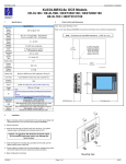
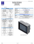
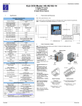
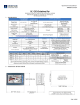
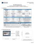
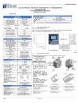
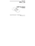
MAN0945-04-EN
Specifications / Installation
XL10e OCS
Base Controller Datasheet
for
HE-XV1E0, HE-XV1E2, HE-XV1E3, HE-XV1E4, HE-XV1E5
HEXT501C100, HEXT501C112, HEXT501C113 HEXT501C114 HEXT501C115
1
Specifications
3
Panel Cut-Out and Dimensions
Specifications
Required
Power
(Steady state)
Required
Power
(Inrush)
Primary
Power Range
Relative
Humidity
Clock
Accuracy
650 mA @ 24 VDC
1.3A @ 12 VDC
25 A for <1 ms @ 24 VDC – DC Switched
15 A for <1 ms @ 12VDC – DC Switched
2.5 A for 1 ms @ 24 VDC - AC Switched
10 – 30 VDC
9.08”
(230.6mm)
5 to 95% Non-condensing
+/- 35 ppm maximum at 25° C
(+/- 1.53 Minutes per Month)
Operating
Temp
-10°C to +60°C
Display Type
10.4” VGA TFT (550 nit typical)
Screen
Resolutions
Display
Memory
640 x 480
11.94” (303.3mm)
2.75 MB
Scan Rate
Controller 0.2 mS/K
Display Life
Minimum 50000 hours (50% brightness, 25 deg C)
User Keys
7 user-defined Function keys and a System Key
Screens
supported
1023
Colors
32768
Weight
70 oz. (2 kg)
CE
USA:
http://www.heapg.com/Pages/TechSupport/ProductCert.
html
Europe:
http://www.horner-apg.com/en/support/certification.aspx
2.43” (61.7mm)
Note: Max. panel thickness: 5 mm.
Refer to the User Manual (MAN0883) for panel box information and a checklist of requirements.
Note: The tolerance to meet NEMA standards is ± 0.005” (0.1 mm).
UL
Serial
Ethernet
USB-A
USB-B
Removable
Media
CAN
Remote I/O
2
Connectivity
2 Serial Ports – Each RS232 & RS485
10/100-Mbps – Auto MDX
For USB Flash Drives
Mini B for connecting to PC (Programming, Envision…)
Removable Media for upto 2 GB of storage for programs,
data logging or screen capture…
Remote I/O, Peer to Peer, PC, Programming…
SmartStix, SmartBlock, SmartMod or SmartRail
1
9
2
5
Installation
7
1. Prior to mounting, observe requirements for the panel layout design and
spacing/clearances in the OCS XL10e Series Manual (MAN0883).
2. Cut the host panel.
6
3. Insert the OCS through the panel cutout (from the front). The gasket
material needs to be between the host panel and the OCS.
8
Caution: Do not force the OCS into the panel cutout.
An incorrectly sized panel cutout can damage the
touch screen.
3
4. Install and tighten the mounting clips (provided with the OCS) until the
gasket material forms a tight seal.
5. Connect cables as needed such as communications, programming, power
and CsCAN cables to the ports using the provided connectors.
10
4
There are 10 mounting clip locations on the XL10e.
For minimal mounting use four clips at 1, 2, 3 & 4 or 5, 6, 7 & 8.
For IP67 mounting use eight clips at locations 1 to 8.
For NEMA 4X mounting use ten clips in all locations.
The unit includes 8 clips order HE500ACC604 for additional
6. Begin configuration procedures.
__________________________________________________________________________________________________________________________________________________________________________
1/24/2011
Page 1 of 4
#1037
MAN0945-04-EN
4
Specifications / Installation
Ports and Connectors
Removable
Media
Memory Slot
USB
Mini B USB 5 pin
programming port
Ethernet
Micro SD Memory Slot:
Uses Removable Memory for
data logging, screen captures,
program loading and recipes.
Horner Part No.: HE-MC1
USB
USB A Port
User Interface
USBA: For flash drive
connectivity
Serial Communications:
MJ1/MJ2: (RS-232 / RS-485)
Used for Cscape programming
and Application-Defined
Communications.
Ethernet: Used for Cscape
programming and ApplicationDefined Communications.
USBB: For network
communication and
programming of OCS
DIP Switches
Serial Comm
MJ1
MJ2
CAN Comm
USB
USB A Port
Power
Ethernet
__________________________________________________________________________________________________________________________________________________________________________
1/24/2011
Page 2 of 4
#1037
MAN0945-04-EN
4.1
Specifications / Installation
Serial Communications:
MJ2 Pinouts in Half and Full Duplex Modes
MJ1: (RS-232 / RS-485) Use for Cscape programming and
Application-Defined Communications.
Pin
Pin
MJ1 Pins
8
1
Functions
RS-232
MJ2 Pins
8
MJ2: (RS-232 / RS-485) Use for Application-Defined
Communications.
1
MJ2 Pins
Signal
Direction
8
TXD
OUT
7
6
RXD
IN
0V
Ground
5*
+5 60mA
OUT
4
TX-
OUT
Signal
Direction
Signal
Direction
8
TXD
OUT
TXD
OUT
7
6
RXD
IN
RXD
IN
0V
Ground
0V
Ground
3
TX+
OUT
5*
+5 60mA
OUT
+5 60mA
OUT
TX-/RX-
IN/OUT
4
RTS
OUT
TX-
OUT
2
1
TX+/RX+
IN/OUT
3
CTS
IN
TX+
OUT
2
1
RX- / TX-
IN / OUT
RX-
IN
RX+ / TX+
IN / OUT
RX+
IN
MJ2 Half Duplex Mode
Pin
MJ2 Pins
8
Table - Ports and Functions
Port 1 (MJ1)
Port 2 (MJ2)
!
!
1
Signal
Direction
8
TXD
OUT
7
6
RXD
0V
IN
Ground
Hardware Handshaking
!
X
5*
+5 60mA
OUT
Programming
!
X
4
TX-
OUT
Ladder function
controlled
Serial Downloable
Protocols
RS 485 Full duplex
RS 485 Half duplex
!
!
3
TX+
OUT
!
!
2
1
RXRX+
IN
IN
X
!
!
!
4.2
* +5V 60mA Max
* +5V 60mA Max
MJ2 Full Duplex Mode
External DIP Switch Settings
As seen when looking at the side of the XL10 unit:
MJ1
On
The DIP Switches are used for
termination of the RS-485 ports. The
XL10 is shipped un-terminated.
To terminate, select one of the DIP
Switches and configure it based upon
the option that is desired.
On
ON enables MJ2 RS485 port termination (121 Ohms).
OFF disables MJ2 RS485 port termination.
SW2 & SW3 - ON places MJ2 RS485 port in half-duplex mode.
OFF places MJ2 RS485 port in full-duplex mode.
Off
SW4 -
On
Off
4.3
SW1 -
Off
ON enables MJ1 RS485 port termination (121 Ohms).
OFF disables MJ1 RS485 port termination.
MJ2
Built-in I/O Details
Models
HE-XV1E2
HEXT501C112
HE-XV1E3
HEXT501C113
HE-XV1E4
HEXT501C114
HE-XV1E5
HEXT501C115
Description
12DC in (4HSC), 6 Relay out, 4 Analog In
Manual
MAN0946
12 DC in (4HSC), 12 DC out (2 PWM), 2 Analog in
24 DC in (4HSC), 16 DC out (2 PWM), 2 Analog in
12 DC in (4HSC), 12 DC out (2 PWM), 2 Universal
Analog In (T/C, RTD, mV, mA, V) & 2 Analog out (mA, V)
MAN0947
MAN0953
__________________________________________________________________________________________________________________________________________________________________________
1/24/2011
Page 3 of 4
#1037
MAN0945-04-EN
4.4
Specifications / Installation
CAN Network Port and Wiring
5
Safety
When found on the product, the following symbols specify:
Warning: Electrical
Shock Hazard.
Warning: Consult
user documentation.
This equipment is suitable for use in Class I, Division 2, Groups A, B, C and D or Non-hazardous
locations only.
WARNING – EXPLOSION HAZARD – Do not disconnect equipment unless power has been switched
off or the area is known to be non-hazardous.
AVERTISSEMENT - RISQUE D'EXPLOSION - AVANT DE DECONNECTOR L'EQUIPMENT,
COUPER LE COURANT OU S'ASSURER QUE L'EMPLACEMENT EST DESIGNE NON
DANGEREUX.
CAN Connector
Use the CAN Connector when
using CsCAN network.
WARNING: To avoid the risk of electric shock or burns, always connect the safety (or earth) ground
before making any other connections.
Torque rating 4.5 – 7 Lb-In
(0.50 – 0.78 N-m)
Pin
1
2
3
4
5
Signal
VCN_L
SHLD
CN_H
V+ (NC)
4.5
NET1 Port Pin Assignments
Signal Description
CAN Ground - Black
CAN Data Low - Blue
Shield Ground - None
CAN Data High - White
No Connect - Red
Direction
!
In/Out
!
In/Out
!
10 BaseT Ethernet (10-Mbps)
100 BaseTx Fast Ethernet (100-Mbps)
Half or Full Duplex
Both 10/100-Mbps and Half/Full Duplex
Shielded RJ-45
Modes
Auto-Negotiation
Connector Type
Cable Type
(Recommended)
Port
WARNING: Replace fuse with the same type and rating to provide protection against risk of fire and
shock hazards.
WARNING: In the event of repeated failure, do not replace the fuse again as a repeated failure
indicates a defective condition that will not clear by replacing the fuse.
WARNING – EXPLOSION HAZARD – Substitution of components may impair suitability for Class I,
Division 2
AVERTISSEMENT - RISQUE D'EXPLOSION - LA SUBSTITUTION DE COMPOSANTS PEUT
RENDRE CE MATERIAL INACCEPTABLE POUR LES EMPLACEMENTS DE CLASSE 1, DIVISION 2.
Ethernet Port
Speeds
WARNING: To reduce the risk of fire, electrical shock, or physical injury it is strongly recommended to
fuse the voltage measurement inputs. Be sure to locate fuses as close to the source as possible.
CAT5 (or better) UTP
Auto MDI/MDI-X
WARNING - The USB parts are for operational maintenance only. Do not leave permanently connected
unless area is known to be non-hazardous.
WARNING – EXPLOSION HAZARD - BATTERIES MUST ONLY BE CHANGED IN AN AREA
KNOWN TO BE NON-HAZARDOUS.
AVERTISSEMENT - RISQUE D'EXPLOSION - AFIN D'EVITER TOUT RISQUE D'EXPLOSION,
S'ASSURER QUE L'EMPLACEMENT EST DESIGNE NON DANGEREUX AVANT DE CHANGER LA
BATTERIE.
WARNING - Battery May Explode If Mistreated. Do Not Recharge, Disassemble or Dispose Of In Fire
4.6
Power Port and Wiring
WARNING: Only qualified electrical personnel familiar with the construction and operation of this
equipment and the hazards involved should install, adjust, operate, or service this equipment. Read
and understand this manual and other applicable manuals in their entirety before proceeding. Failure to
observe this precaution could result in severe bodily injury or loss of life.
Power Connector
Power Up:
Connect to Earth Ground.
Apply 10 - 30 VDC.
Screen lights up with slight delay.
Torque rating 4.5 – 7 Lb-In
(0.50 – 0.78 N-m)
Primary Power Port Pins
Description
Pin
Signal
1
Ground
Frame Ground
2
V-
Input Power Supply Ground
3
V+
Input Power Supply Voltage
6
This device complies with part 15 of the FCC Rules. Operation is subject to the following two
conditions:
1. This device may not cause harmful interference.
2. This device must accept any interference received, including interference that may cause
undesired operation.
Radiated Emission Compliance: For compliance requirement, a ferrite (Horner P/N FBD006 supplied
with the unit) needs to be placed on the AC/DC line with one loop.
" All applicable codes and standards need to be followed in the installation of this product.
" Adhere to the following safety precautions whenever any type of connection is made to the module:
# Connect the safety (earth) ground on the power connector first before making any other connections.
# When connecting to electric circuits or pulse-initiating equipment, open their related breakers.
# Do not make connections to live power lines.
# Make connections to the module first; then connect to the circuit to be monitored.
# Route power wires in a safe manner in accordance with good practice and local codes.
# Wear proper personal protective equipment including safety glasses and insulated gloves when
making connections to power circuits.
# Ensure hands, shoes, and floor are dry before making any connection to a power line.
# Make sure the unit is turned OFF before making connection to terminals.
# Make sure all circuits are de-energized before making connections.
# Before each use, inspect all cables for breaks or cracks in the insulation. Replace immediately
if defective.
Technical Support
For assistance and manual updates, contact Technical Support at the
following locations:
North America:
Tel: 317 916-4274
Fax: 317 639-4279
Web: http://www.heapg.com
Email: [email protected]
No part of this publication may be reproduced without the prior agreement and written permission of
Horner APG, Inc. Information in this document is subject to change without notice.
Europe:
Tel: +353-21-4321266
Fax: +353-21-4321826
Web: http://www.horner-apg.com
Email: [email protected]
__________________________________________________________________________________________________________________________________________________________________________
1/24/2011
Page 2 of 4
#1037