1
User Manual for
HE800JCM205
SmartStack SAE J1939
Communication Module
03 December 2002
MAN0546-03
PREFACE
03 DEC 2002
PAGE 3
MAN0546-03
PREFACE
This manual explains how to use SmartStack SAE J1939 Communication Modules.
Copyright (C) 2002 Horner APG, LLC., 640 North Sherman Drive Indianapolis, Indiana 46201. All rights
reserved. No part of this publication may be reproduced, transmitted, transcribed, stored in a retrieval
system, or translated into any language or computer language, in any form by any means, electronic,
mechanical, magnetic, optical, chemical, manual or otherwise, without the prior agreement and written
permission of Horner APG, Inc.
All software described in this document or media is also copyrighted material subject to the terms and
conditions of the Horner Software License Agreement.
Information in this document is subject to change without notice and does not represent a commitment on
the part of Horner APG.
SmartStack is a trademark of Horner APG.
For user manual updates, contact Horner APG Technical Support
Division, at (317) 916-4274 or visit our website at www.heapg.com.
PAGE 4
MAN0546-03
03 DEC 2002
PREFACE
LIMITED WARRANTY AND LIMITATION OF LIABILITY
Horner APG,LLC. ("HE-APG") warrants to the original purchaser that the SmartStack SAE J1939 Communication
Module manufactured by HE-APG is free from defects in material and workmanship under normal use and service.
The obligation of HE-APG under this warranty shall be limited to the repair or exchange of any part or parts which
may prove defective under normal use and service within two (2) years from the date of manufacture or eighteen (18)
months from the date of installation by the original purchaser whichever occurs first, such defect to be disclosed to
the satisfaction of HE-APG after examination by HE-APG of the allegedly defective part or parts. THIS WARRANTY
IS EXPRESSLY IN LIEU OF ALL OTHER WARRANTIES EXPRESSED OR IMPLIED INCLUDING THE
WARRANTIES OF MERCHANTABILITY AND FITNESS FOR USE AND OF ALL OTHER OBLIGATIONS OR
LIABILITIES AND HE-APG NEITHER ASSUMES, NOR AUTHORIZES ANY OTHER PERSON TO ASSUME FOR
HE-APG, ANY OTHER LIABILITY IN CONNECTION WITH THE SALE OF THIS SmartStack SAE J1939
Communication Module. THIS WARRANTY SHALL NOT APPLY TO THIS SmartStack SAE J1939 Communication
Module OR ANY PART THEREOF WHICH HAS BEEN SUBJECT TO ACCIDENT, NEGLIGENCE, ALTERATION,
ABUSE, OR MISUSE. HE-APG MAKES NO WARRANTY WHATSOEVER IN RESPECT TO ACCESSORIES OR
PARTS NOT SUPPLIED BY HE-APG. THE TERM "ORIGINAL PURCHASER", AS USED IN THIS WARRANTY,
SHALL BE DEEMED TO MEAN THAT PERSON FOR WHOM THE SmartStack SAE J1939 Communication Module
IS ORIGINALLY INSTALLED. THIS WARRANTY SHALL APPLY ONLY WITHIN THE BOUNDARIES OF THE
CONTINENTAL UNITED STATES.
In no event, whether as a result of breach of contract, warranty, tort (including negligence) or otherwise, shall HEAPG or its suppliers be liable of any special, consequential, incidental or penal damages including, but not limited to,
loss of profit or revenues, loss of use of the products or any associated equipment, damage to associated equipment,
cost of capital, cost of substitute products, facilities, services or replacement power, down time costs, or claims of
original purchaser's customers for such damages.
To obtain warranty service, return the product to your distributor with a description of the problem, proof of
purchase, post paid, insured and in a suitable package.
ABOUT PROGRAMMING EXAMPLES
Any example programs and program segments in this manual or provided on accompanying diskettes are included
solely for illustrative purposes. Due to the many variables and requirements associated with any particular
installation, Horner APG cannot assume responsibility or liability for actual use based on the examples and diagrams.
It is the sole responsibility of the system designer utilizing the SmartStack SAE J1939 Communication Module to
appropriately design the end system, to appropriately integrate the SmartStack SAE J1939 Communication Module
and to make safety provisions for the end equipment as is usual and customary in industrial applications as defined in
any codes or standards which apply.
Note: The programming examples shown in this manual are for illustrative
purposes only. Proper machine operation is the sole responsibility of the
system integrator.
PREFACE
03 DEC 2002
REVISIONS TO THIS MANUAL
1.
Revised module operation (Chapter 2).
PAGE 5
MAN0546-03
PAGE 6
MAN0546-03
03 DEC 2002
PREFACE
PREFACE
03 DEC 2002
PAGE 7
MAN0546-03
Table of Contents
CHAPTER 1: INTRODUCTION........................................................................................................... 9
1.1
Overview ..............................................................................................................................9
1.2
Product Description ...............................................................................................................9
1.3
Functional Description ...........................................................................................................9
1.4
Technical Support ............................................................................................................... 10
CHAPTER 2: OPERATION .............................................................................................................. 11
2.1
General............................................................................................................................... 11
2.2
Two Communication Methods for Handling Data ................................................................... 11
2.3
Register Definitions ............................................................................................................. 11
2.4
Scanning ............................................................................................................................ 13
2.4.1
Receive Table Configuration.......................................................................................... 13
2.5
Timed Transmit – Table ....................................................................................................... 14
2.6
Timed Transmit – Data ........................................................................................................ 15
CHAPTER 3: CONFIGURATION ...................................................................................................... 17
3.1
General............................................................................................................................... 17
3.2
Configuration....................................................................................................................... 17
PAGE 8
MAN0546-03
03 DEC 2002
PREFACE
CH. 1
03 DEC 2002
PAGE 9
MAN0546-03
CHAPTER 1: INTRODUCTION
1.1
Overview
The HE800JCM205 is a SmartStack SAE J1939 Communication Module. SAE J1939 (J1939) is a CANbased protocol used in truck and bus control communications networks. There are various layers to the
J1939 protocol that are described in SAE J1939 documents. J1939 uses a 29-bit identifier requiring
hardware that can support CAN 2.0B. The baud rate is fixed at 250Kbps. SAE J1939 specifies a table of
Parameter Group Numbers (PGNs). A PGN is unique numeric identifier that is associated with a specific
parameter name. A PGN is used to define the parameter value a device is requesting or the parameter
value that a device is sending.
Note: SAE is an acronym for Society of Automotive Engineers.
1.2
Product Description
There are 2 operational bi-colored LEDs on the side of the module. One LED is green indicating the
module is OK. The other LED flashes orange, indicating network traffic.
1.3
Functional Description
The JCM205 can request/monitor data from and transmit data to devices on the J1939 network. There
are 10 receive buffers and 10 transmit buffers that can be configured for handling data. The configuration
is accomplished using PLC registers and ladder logic. This allows for “on-the-fly” configuration changes.
For detailed information, refer to Chapter 2: Operation.
PAGE 10
MAN0546-03
1.4
03 DEC 2002
Technical Support
For assistance, contact Technical Support at the following locations:
North America:
(317) 916-4274
www.heapg.com
Europe:
(+) 353-21-4321-266
www.horner-apg.com
CH.1
CH. 2
03 DEC 2002
PAGE 11
MAN0546-03
CHAPTER 2: OPERATION
2.1
General
Chapter Two covers operational information for the JCM205.
2.2
Two Communication Methods for Handling Data
The JCM205 can request and monitor data from and transmit data to devices on the J1939 network.
There are two communication methods used for handling data. The first method is Scanning in which
Parameter Group Numbers (PGNs) are loaded into up to 10 receive tables, and the module continuously
gathers data for the configured PGNs. The second method is a Timed Transmit in which up to 10
transmit tables are configured to send a message every X number of milliseconds. The following sections
cover each communication method in detail.
2.3
Register Definitions
Both communication methods share the same AQ registers for configuring the receive and transmit
tables. Some of the AQ register definitions change for the two buffers.
A total of 14 %AQs, 16 %Qs and 32 %Is are used for the configuration and module operation. The
starting locations are configured through the I/O configuration in Cscape. The total number of %R
registers used will vary depending on the configured tables.
Table 2.1 - %AQ Definitions for Receive Table
%AQ
Description
Register
Table Number (0-9)
AQx
Source
Address (0-255)
AQx+1
PGN
(PF & PS)
AQx+2
Priority
(0-7)
AQx+3
Number
of
bytes
AQx+4
Scan
Method
(0=Monitor
1=Request)
AQx+5
Starting
%R
register
to
store
data
AQx+6
Not
Used
AQx+7
Not Used
AQx+8
Not Used
AQx+9
Not Used
AQx+10
Not Used
AQx+11
Not Used
AQx+12
Not Used
AQx+13
Table 2.2 - %AQ Definitions for Transmit Table
%AQ
Description
Register
Table Number (0-9)
AQx
Source
Address (0-255)
AQx+1
PGN
(PF & PS)
AQx+2
Priority
(0-7)
AQx+3
Number
of
bytes
AQx+4
Time
Interval
in
milliseconds
AQx+5
Transmit data Byte 1
AQx+6
Transmit data Byte 2
AQx+7
Transmit data Byte 3
AQx+8
Transmit data Byte 4
AQx+9
Transmit data Byte 5
AQx+10
Transmit data Byte 6
AQx+11
Transmit data Byte 7
AQx+12
Transmit data Byte 8
AQx+13
PAGE 12
MAN0546-03
03 DEC 2002
Table 2.3
%Q Register
Qx
Qx+1
Qx+2
Qx+3
Qx+4
Qx+5
Qx+6
Qx+7
Qx+8
Qx+9
Qx+10
Qx+11
Qx+12
Qx+13
Qx+14
Qx+15
CH. 2
- %Q Definitions
Description
TX Data Buffer 0 Update
TX Data Buffer 1 Update
TX Data Buffer 2 Update
TX Data Buffer 3 Update
TX Data Buffer 4 Update
TX Data Buffer 5 Update
TX Data Buffer 6 Update
TX Data Buffer 7 Update
TX Data Buffer 8 Update
TX Data Buffer 9 Update
Spare
Spare
Spare
Spare
RX Table Update
TX Table Update
Table 2.4 - %I Definitions
%I Register
Ix
Ix+1
Ix+2
Ix+3
Ix+4
Ix+5
Ix+6
Ix+7
Ix+8
Ix+9
Ix+10
Ix+11
Ix+12
Ix+13
Ix+14
Ix+15
Ix+16
Ix+17
Ix+18
Ix+19
Ix+20
Ix+21
Ix+22
Ix+23
Ix+24
Ix+25
Ix+26
Ix+27
Ix+28
Ix+29
Ix+30
Ix+31
Description
TX Data Buffer 0 Update Ack
TX Data Buffer 1 Update Ack
TX Data Buffer 2 Update Ack
TX Data Buffer 3 Update Ack
TX Data Buffer 4 Update Ack
TX Data Buffer 5 Update Ack
TX Data Buffer 6 Update Ack
TX Data Buffer 7 Update Ack
TX Data Buffer 8 Update Ack
TX Data Buffer 9 Update Ack
Spare
No RX Timeout
Bus Off Error
Power Fail Error
RX Table Update Ack
TX Table Update Ack
TX Data Buffer 0 Update Error
TX Data Buffer 1 Update Error
TX Data Buffer 2 Update Error
TX Data Buffer 3 Update Error
TX Data Buffer 4 Update Error
TX Data Buffer 5 Update Error
TX Data Buffer 6 Update Error
TX Data Buffer 7 Update Error
TX Data Buffer 8 Update Error
TX Data Buffer 9 Update Error
Spare
Spare
Spare
Spare
RX Table Update Error
TX Table Update Error
CH. 2
2.4
03 DEC 2002
PAGE 13
MAN0546-03
Scanning
The Scanning method uses a scan table that contains a series of PGNs and associated information.
Data for the configured PGNs is continuously gathered and sent to the PLC. There are two modes for
gathering data from devices on the J1939 network, monitor and request. Each PGN in the scan table is
configured to use one of the two modes for gathering data. The JCM205 does not know which PGNs
require monitoring and which PGNs require requesting; it is the responsibility of the individual configuring
the module to enter the information. Otherwise, the data may not be updated.
a.
Monitor Mode
An engine control module (ECM) sends some PGN data onto the network at regular intervals. The
specific PGNs that are sent vary between ECMs. If the ECM broadcasts a desired PGN’s data on a
regular basis, then the mode for that PGN is configured for monitor.
Monitoring does not require interaction between the JCM205 and a device on the network. The JCM205
monitors the network for the PGNs that are configured as monitor mode in the scan table. If it finds a
match, then the data is sent to the PLC. In this mode, the source address is not used.
b.
Request Mode
If the desired PGN is not sent on a regular basis, then a request must be made from the JCM205 to the
device before the data is sent. The mode for these PGNs are configured for request.
Requesting requires interaction between the JCM205 and a device on the network. The JCM205 must
send a request message to a device onto the network and receive a reply before that data can be sent to
the PLC. In this mode, the source address is required.
2.4.1
Receive Table Configuration
The receive table is configured by loading the AQ registers with the correct scan information and setting
the RX Table Update bit (Qx+14). The JCM205 copies the information from the AQ registers into the corresponding
receive table when the RX Table Update bit transitions from a 0 to 1. The RX Table Update Ack bit (Ix+14) is set
when the JCM205 finishes updating the table. If an error occurs then the RX Table Update Error bit will also be set
Otherwise, it will be clear indicating that there were no errors in data stored in the table.
REGISTER DEFINITIONS:
Buffer Number (0-9) – JCM205 receive table number in which to load the scan information.
Source Address (0-255) – Source address used when requesting data. It is not used for monitoring data. (Part of the
ID value)
PGN [PF & PS] (0-65535) – Predefined number in the SAE documents associated with the specific parameter that is
to monitored. (Part of the ID value)
Priority (0-7) – Arbitration Priority where 0 is highest and 7 is lowest. (Part of the ID value)
Number of Bytes – Number of bytes expected
Scan Method (0 or 1) – 0=Monitor and 1=Request
Starting %R Register – Starting %R register that will contain the first byte of received data. Subsequent %R registers
will contain the remaining bytes of data up to the Number of Bytes.
PAGE 14
MAN0546-03
03 DEC 2002
CH. 2
EXAMPLE:
In the following example, all registers start at 1 (%Q1, %AQ1, %I1). Eight bytes of Electronic Engine
Controller #1 data is broadcast on the network so the receive table will be configured to monitor for the
data.
1) Load the %AQ registers:
AQ1: 5 (Using buffer number 5)
AQ2: 251 (Extra source address area, not used for monitoring)
AQ3: 61444 (PGN for Electronic Engine Controller #1)
AQ4: 7 (Lowest priority, not used for monitoring)
AQ5: 8 (8 bytes of data)
AQ6: 0 (Monitor)
AQ7: 100 (Recevied data will start at %R100)
2) Transition %Q15 from 0 to 1 (RX Table Update bit )
3) Wait for %I15 to go to 1
4) Check %I31:
I31 = 0 – Table update was successful
I31 = 1 – Table updated fail (On or more %AQ data out of range)
5) Transitions %Q15 from 1 to 0
6) %I15 and %I31 clear
RESULT:
%R100-%R107 will contain the data received for PGN 61444.
The same procedure is used to update receive tables 0-9. Any one of the receive tables can be updated at anytime.
2.5
Timed Transmit – Table
The transmit table is configured by loading the AQ registers with the correct scan information and setting
the TX Table Update bit (Qx+15). The JCM205 copies the information from the AQ registers into the corresponding
transmit table and the data from the configured %R registers when the TX Table Update bit transitions from a 0 to 1.
Note that both the transmit table and trasmit data are updated. The TX Table Update Ack bit (Ix+15) is set when the
JCM205 finishes updating the table. If an error occurs then the TX Table Update Error bit will also be set Otherwise,
it will be clear indicating that there were no errors in data stored in the table.
REGISTER DEFINITIONS:
Buffer Number (0-9) – JCM205 transmit table number in which to load the scan information.
Source Address (0-255) – Source address used when transmitting data. It is not used for monitoring data. (Part of
the ID value)
PGN [PF & PS] (0-65535) – Predefined number in the SAE documents associated with the specific parameter that is
to sent. (Part of the ID value)
Priority (0-7) – Arbitration Priority where 0 is highest and 7 is lowest. (Part of the ID value)
Number of Bytes (1-8) – Number of bytes to load into the transmit buffer (8 bytes are always sent)
Time Interval (0, 15-60000) – Number of milliseconds between transmits. 0=stop transmitting
Transmit data – Registers that contain the transmit data to load in to the transmit data buffer
CH. 2
03 DEC 2002
PAGE 15
MAN0546-03
EXAMPLE:
In the following example, all registers start at 1 (%Q1, %AQ1, %I1). Eight bytes of Electronic Engine
Controller #1 data is broadcast on the network so the transmit table will be configured to send the data
every 50ms.
1) Load the %AQ registers:
AQ1: 5 (Using buffer number 5)
AQ2: 251 (Source address)
AQ3: 61444 (PGN for Electronic Engine Controller #1)
AQ4: 7 (Lowest priority, not used for monitoring)
AQ5: 8 (8 bytes of data)
AQ6: 50 (50ms)
AQ7: 00 (Start of Transmit data)
AQ8: 11
AQ9: 22
AQ10: 33
AQ11: 44
AQ12: 55
AQ13: 66
AQ14: 77
2) Transition %Q16 from 0 to 1 (TX Table Update bit )
3) Wait for %I16 to go to 1
4) Check %I32:
I32 = 0 – Table update was successful
I32 = 1 – Table updated fail (On or more %AQ data out of range)
5) Transitions %Q16 from 1 to 0
6) %I16 and %I32 clear
RESULT:
The transmit table 5 will be updated to send data that was stored in %R200-%R207 for PGN 61444 every
50ms.
The same procedure is used to update transmit tables 0-9. Any one of the transmit tables can be
updated at anytime.
2.6
Timed Transmit – Data
The transmit table is configured by loading the AQ registers with the correct scan information and setting
the TX Table Update bit (Qx+15). The JCM205 copies the information from the AQ registers into the
corresponding transmit table and data table when the TX Table Update bit transitions from a 0 to 1. Note
that both the transmit table and trasmit data are updated. The TX Table Update Ack bit (Ix+15) is set
when the JCM205 finishes updating the table. If an error occurs then the TX Table Update Error bit will
also be set Otherwise, it will be clear indicating that there were no errors in data stored in the table.
PAGE 16
MAN0546-03
03 DEC 2002
EXAMPLE:
In the following example, transmit table 5 has already been configured.
1) Load the %AQ registers with new data:
AQ7: 00 (Start of Transmit data)
AQ8: 11
AQ9: 22
AQ10: 33
AQ11: 44
AQ12: 55
AQ13: 66
AQ14: 77
2) Transition %Q5 from 0 to 1 (TX Data Buffer Update bit)
3) Wait for %I5 to go to 1
4) Check %I21:
I21 = 0 – Data buffer update was successful
I21 = 1 – Data buffer updated fail
5) Transitions %Q5 from 1 to 0
6) %I5 and %I21 clear
RESULT:
The transmit data buffer 5 will be updated with new data was stored in %AQ7-%AQ14.
CH. 2
CH. 3
03 DEC 2002
PAGE 17
MAN0546-03
CHAPTER 3: CONFIGURATION
3.1
General
Chapter Three covers the configuration of the JCM205. The purpose of the configuration is to allow
communication between an OCS/RCS and an Engine Control Module.
Note: To perform this configuration, it is necessary to consult the engine manufacturer’s user
documentation to determine parameter numbers and the corresponding number of words
for each parameter.
3.2
Configuration
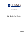
a. First, invoke Cscape. From the Cscape Main Menu, select Controller | I/O Configure… .
Ensure the correct
controller is
selected. To change
controllers, press
CPU Slots and
select the desired
module.
You can add an I/O
module to any slot,
but Slot 1 must not
be empty.
Figure 3.1 – Select the Module Slot
Ensure that the desired controller is selected. The OCS300-CsCAN is shown as the selected controller
(Fig. 3.1) in this example. If satisfied with the controller selection, press a Base # tab, and go to Step 3.
If a different controller is desired (as it is in this configuration example), continue Step 2.
Note: The Auto Config System button can be pressed prior to selecting the desired controller and I/O.
By pressing the button, the settings are deleted from any controller and I/O that is physically connected to
the PC. A dialog box appears and indicates that settings will be deleted from currently configured
models. If OK, press Yes. Then press OK.
PAGE 18
MAN0546-03
03 DEC 2002
CH. 3
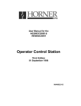
Figure 3.2 – Select the Comm tab
b. Next, double-click on the empty slot in which the JCM205 module will reside, or click on the Config
button to the right of the slot position. This invokes the Add I/O Module screen. Click on the Comm tab.
From that dialog, select the JCM205 module, and click OK.
Figure 3.3 – JCM205 Module is Added
c. The screen returns to the Configure I/O dialog box - with the selected slot showing that the JCM205
module has been added.
Double-click on the JCM205 module in the I/O configuration screen (Figure 3.3) or click on the Config
button next to the JCM205 module.
CH. 3
03 DEC 2002
PAGE 19
MAN0546-03
d. The following screen appears: Two tabs are available for selection:
Figure 3.4 – Module Configuration
I/O Map Tab
NOTE:
Ignore this screen at this point. The registers can be varied during configuration.
Module Setup Tab
The Module Setup screen has two important functions.
Figure 3.5 – Module Setup Tab
Function 1: Pressing the Module Setup tab displays a screen with a Configure button.
Pressing the Configure button opens the following Configurator screen.
Function 2:
After you finish with the Configurator, be sure to return to this screen and
press OK (or CANCEL) to save (or cancel) all changes..
PAGE 20
MAN0546-03
03 DEC 2002
CH. 3
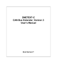
e. The following screen appears.
Register Entry
focuses on 3 register types:
%Q, %AQ, %I. These types
have a fixed number of
registers.
14
14
Figure 3.6 - JCM205 Configuration Program
Standard Configuration
The JCM205 has a fixed number of 16 %Qs, 32 %Is, and 14 %AQs.
Type: Displays the register types assigned to the module.
Starting Register: Denotes the starting location of the register type. These are user-editable fields.
Ending Register: Denotes the ending location of the register type. These fields are automatically
updated by the Configurator.
Number: Indicates the quantity of a particular register type. These fields are automatically updated by
the Configurator.
CH. 3
03 DEC 2002
PAGE 21
MAN0546-03
f. During the configuration, it is possible that the following screen appears. In the event that it does
appear, press the HE800JCM205 Configurator button (located on the Menu bar at the very bottom of the
screen) to return to the configuration screen. This screen simply prompts you to close the JCM205 editor
to continue.
Figure 3.7 - PGN Configuration
g. You need to save the configuration changes by exiting the configuration screen (Click the X in the
upper right corner) and then returning to the Module Setup screen.
Figure 3.8 – Module Setup Tab
h. To save or cancel your settings, be sure to return to this screen and press OK or CANCEL.
PAGE 22
MAN0546-03
03 DEC 2002
NOTES
CH. 3