1
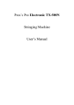
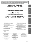
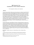
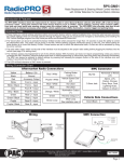
ALPINE 6600
STRINGING MACHINE
USER’S MANUAL
0
1. ANATOMY
15
16
17
28
9
11
12
27
18
19
10
20
13
21
1
14
22
3
4
26
5
25
6
24
7
23
8
2
1
1. machine body
2. floor stand
3. height adjustment
4. brake
5. tool tray
6. string reel holder
7. column
8. H-base/foot
9. rubber cover
10. center support adjustment knob
11. top of the throat mounting stock
12. bottom of the throat mounting stock
13. head mounting stock
14. upper tray table
15. side support
16. gliding clamp
17. glide bar
18. string gripper
19. tension locking lever
20. display
21. power button
22. tension setting knob
23. tension head handle/crank
24. tension head cover/housing
25. stopper
26. tension head rail
27. side support arm adjustment knob
28. center support
2
3
4
5
6
3.
Lightly tighten center supports by turning the knobs on the outside of the
center support clockwise.
3.
Rotate the side support arm adjustment knobs clockwise until
the firm contact is made between the side supports and the racquet frame.
If the side supports can’t contact the frame squarely when the arms are closed
against the racquet, please insert the side supports onto the other holes of
the side support arms.
Apply a final adjustment to all racquet support points until the racquet is firmly
secured in the mounting system.
4
4
3
3
4
4
7
4. KEYPAD OPERATING INSTRUCTIONS
Step 1 : Battery Setting
Set one dry battery (9 volts) beneath the tension head.
Caution : position + and – correctly.
Step 2 : Power Button
To turn the machine on, press the black
POWER-KG/LB button for 1 second until
a tension appears on the display.
NOTE the power save function has been set
for 1 minute at factory before shipping so the
display will shut down automatically after 1
minute. To motivate the display, repeat the
procedure step 2 again.
To turn power off, press the black
POWER-KG/LB button for 2 seconds
until OFF appears on the display.
Or wait for 1 minute till the power save
function is motivated and display will
shut down automatically as well.
Step 3 : KG/LB Button
Press the black POWER-KG/LB button for 0.5 second to change tension display from
KG to LB. To set tension unit from LB to KG, press the black POWER-KG/LB button
for 0.5 second again.
8
5. TENSIONING
Step 1 : Setting Tension
Set the tension by rotating the tension setting
knob counter-clockwise to increase the tension
or clockwise to decrease the tension until the
desired tension appears on the display.
Step 2 : Pulling the Strings
To pull the string, continue rotating the tension head crank/handle backward until the
tension locking lever clicks out. This locks the tension head to the tension rail.
Step 3 : Releasing the Strings
To release the string after clamping,
hold on to tension head and push tension
locking lever back up into the catch on
the tension head. Lift the string out of
the string gripper for the next hole.
9
6. TENSION CALIBRATION
Step 1 :
Set the tension scale on 60 lbs. Place a string attached to a tension calibrator in string
gripper. Tension calibrator will indicate the pounds of tension on tension head under
actual stringing conditions. Pull string until the locking lever releases. If it releases
before 60 lbs or after 60 lbs., the following adjustment is needed. CAUTIION:
Be sure to release string holding tension calibrator. You are now ready for adjustment.
Step 2 :
Loosen the safety screw A. If the locking lever release before 60 lbs., turn the
adjustment screw B counterclockwise until the scale reading matches the calibrator’s;
if the locking lever release after 60 lbs., turn the adjustment screw B clockwise.
WARNING: Be sure to tighten the safety screw A after the adjustment has been
made.
10