1
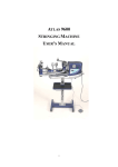
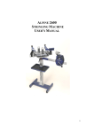
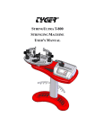
ATLAS 8600
STRINGING MACHINE
USER’S MANUAL
1
ANATOMY
The Atlas 8600 is shipped to you in two cartons.
Here is what the two cartons contain:
1). Electronic Tension Head
2). Racquet Mount and Floor Stand
5
2
1
11
10
12
26
3
13
14
15
4
16
6
25
7
8
18
24
17
9
19
20
21
27
22
23
2
1.
3.
5.
7.
9.
11.
13.
15.
17.
19.
21.
23.
25.
27.
Side Support
Rubber Cover
Side Support Arm Adjustment Knob
Mounting Stock Locking Knob
Turntable Track
String Clamp Base
Rotary String Gripper
Upper Housing
Control Panel
Height Adjustment Knob
String Reel Holder
Foot (Base)
Tension Adjustment Knob
Power Cord
2.
4.
6.
8.
10.
12.
14.
16.
18.
20.
22.
24.
26.
3
Center Support
Center Support Adjustment Knob
Mounting Stock
Turntable
String Clamp
Side Support Arm
Green Tension Button
Lower Housing
Side Panel
Tool Tray
Column
Rubber Foot
Shoulder
ASSEMBLY
Step 1 :
Secure column to
foot using 4 long
bolts, washers
and nuts by a 6
mm and a12 mm
wrenches.
Step 2 :
Remove the 4 nuts from the machine body. Place
machine body over column and align the 4 studs
under the machine with the corresponding holes in
the anchor plate. Secure the 4 nuts to the 4 studs.
Screw the string
reel holder into
the column.
Mount the tool
tray on the
column with the 4 small bolts by a 10 mm
wrench.
Insert the anchor plate in the column and
adjust the anchor post to the proper height and
lock with the adjustment knob.
Step 3 :
Screw the brake into the hole of the lower housing.
To lock the turntable, rotate the brake clockwise.
To unlock the turntable, rotate the brake
counter-clockwise.
Step 4 :
Remove the 4 Allen bolts from the
bearing pivot and insert turntable in machine body.
Tighten the 4 Allen bolts.
4
MOUNTING THE RACQUET FRAME
3.1
1
3.1
3.2
3.2
2
2
3.2
3.2
3.1
3.1
1.
Loosen both mounting stocks by turning the mounting stock knobs
counterclockwise. Place the racquet properly on both mounting stocks.
Adjust the distance between the mounting stocks to accommodate the size of
the racquet frame. Turn both mounting stock knobs clockwise to lock both
mounting stocks in place. Do not apply excessive force or over tighten the
mounting stock knobs; this will damage the parts. Check that the
two swivel clamps can reach all the stringing area of the racquet frame.
2.
Lightly tighten center supports by turning the knobs on the outside of the
center support clockwise.
3.1. The side supports are adjustable to provide support to the racquet frame.
Open side support arms by turning four side support arm adjustment knobs
counterclockwise. Insert the four side supports onto the proper holes of
the side support arms. Note the big jaw of the side support is for tennis racquet
frame and small jaw is for the badminton racquet frame.
3.2. Rotate the side support arm adjustment knobs clockwise until the firm contact
is made between the side supports and the racquet frame.
If the side supports can’t contact the frame squarely when the arms are closed
against the racquet, please insert the side supports onto the other holes of
the side support arms.
Apply a final adjustment to all racquet support points until the racquet is firmly
secured in the mounting system.
5
SWIVEL CLAMP OPERATION
1. If gripper of the string clamp is over tension, turn the round adjustment of the
string clamp counterclockwise to the correct tension by needle nose pliers or
fingers adjusting directly.
2. If gripper of the string clamp doesn’t hold string well, turn the round
adjustment of the string clamp clockwise to the correct tension by needle nose
pliers or fingers adjusting directly.
Needle Nose Pliers Adjustment
Fingers Adjustment
6
SWIVEL CLAMP BASE OPERATION
1.
Lift up the base handle and turn it counterclockwise.
Lower the handle and turn it clockwise.
Repeat the process until the base is locked in place.
2.
The handle position could be at any desired position.
To adjust it, lift up the base handle, turn it to the desired position,
then lower the handle.
B
C
7
D
A
KEYPAD OPERATING INSTRUCTIONS
The keypad is protected by a plastic film that should be removed before using.
POWER ON/OFF
When the machine is turned on, the indicator light of the “POWER ON/OFF” will
light up.
REACHED TENSION
When the desired tension is attained, the indicator light of the “REACHED
TENSION” will light up.
KG/LB
Selects tension scale. Shown on right of screen.
REVERSE
Releases string tension, although this is normally done by pressing the main green
tension button. This key is also used to release the rotary string gripper on occasions
when it comes to rest in a dead spot and does not respond to the main green tension
button.
START
Initiates string tensioning, although this is normally done by pressing the main green
tension button.
8
PRE-STRETCH
Pulls string, release string and re-pulls to the tension setting.
Presses the key of the “PRE-STRETCH” to set up the function of “PRE-STRETCH”
and presses it again to cancel the “PRE-STRETCH” function. The indicator light of
the “PRE-STRETCH” lights up to indicate the “PRE-STRETCH” is set.
TENSION CALIBRATION
Turns the machine on while pressing the “TENSION CALIBRATION” button and
CAL appears on the display along with a tension such as 5 KG and then the indicator
light of the “TENSION CALIBRATION” lights up to indicate the “TENSION
CALIBRATION” is set.
MUTE/MODE/MEMORY
MUTE function :
Presses “MUTE/MODE/MEMORY” to cancel the beep sound. Sets up the beep sound
by pressing “MUTE/MODE/MEMORY” key again.
MODE function :
For troubleshooting purpose and factory setting only.
MEMORY function :
Stores the new calibrated tension during tension calibration.
POWERING
The main power switch is located on the right of the machine next to the receptacle
for the power cord. A 2 amp fuse is located in the power cord receptacle.
Voltage between 100V and 110V (50 Hz to 60 Hz) is acceptable. A grounded outlet
must be used.
9
TENSIONING
To insert the string in the split rotary string
gripper, pass over the top half of the gripper,
wrap the string clockwise around the gripper
drum and position the string between the
gripper jaws as shown in the illustration.
Excessive slack in the string should be
removed before applying tension.
To set the desired tension, rotate the tension
adjustment knob clockwise to increase the displayed
tension or counter-clockwise to decrease the
displayed tension until the desired tension is shown
up on screen.
To tension the string, press the main green tension button
or “START” key on the keypad. As the rotary string
gripper turns and applies tension to the string, the upper
jaw is forced down to clamp the string between the jaws.
To release the tensioned string after clamping, press the main green tension button
again or “REVERSE” key on the keypad.
NOTE :
If the rotary string gripper does not release the string by
pressing the main green tension button, depress the
“REVERSE” key on the keypad to release the string.
10
TENSION CALIBRATION
If your machine is pulling tension inaccurately, please follow the procedures below for
the correct tension calibration.
Step 1 :
Turn the machine on and set 5 KG (or 11 lbs)
by rotating the tension adjustment knob
counterclockwise.
Step 2 :
Turn the machine off.
Step 3 :
Turn the machine on again while pressing “TENSION CALIBRATION" key.
CAL appears on the display along with a tension such as 5 KG (or 11 LB). NOTE : The
indicator light of the “TENSION CALIBRATION” will light up to indicate you have entered
into the tension calibration mode successfully. If not, please repeat the procedure step 3
again.
11
Step 5 :
Note the tension reading on the calibrator
and release the tensioned string by pressing
the main green tension button.
Step 4 :
Pull the string by pressing the main green
tension button.
Step 6 -1 :
Rotate the tension adjustment knob clockwise to
increase the calibrator’s value if the tension reading on
the calibrator is lower than the tension value shown on
the display. (Instead, rotate the tension adjustment knob
counterclockwise to decrease the calibrator’s value if the
tension reading on the calibrator is higher than the
tension value shown on the display.)
NOTE :
One turn of the tension adjustment knob is around 1 KG
(or 3 LB).
Step 6 -2 :
Re-pull the string of the tension calibrator by pressing
the tension green button to see if your adjustment has
attained the correct tension or not.
Step 6 -3 :
If the tension reading on the calibrator is still different
from the tension shown on the display, release the string
and repeat the procedure step 6-1 and 6-2 again.
Step 6 -4 :
If the tension reading on the calibrator is identical to the tension shown on the display, release
the string and press “MEMORY” key to store what you have calibrated and enter into the
next calibration mode, such as 10 KG (or 22 LB).
12
Step 7 :
Before doing the next tension calibration, rotate the
tension adjustment knob clockwise first for 5 turns so
as to start testing the next new tension.
Besides the premier 5 kg (or 11 lbs), the machine will
provide you with six more tensions (such as 10, 15,
20, 25, 30 and 35 kg) or (22, 33, 44, 55, 66 and 77 lbs)
to test against the calibrator. Repeat the procedures
outlined in steps 4 to 7 for each of the rested six
tensions.
Step 8 :
Press “MEMORY” key to store the last calibrated tension and then press “TENSION
CALIBRATION” key to get out the caliation mode or turn power off.
13