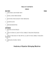
1
TITAN 7600
STRINGING MACHINE
USER’S MANUAL
1
ANATOMY
5
4
3
14
13
12
11
22
23
6
28
7
29
8
9
1
25
10
16
17
15
27
18
19
24
26
20
2
21
2
1. Machine Body along Tension-Head Assembly
2. Floor Stand
3. Swivel Clamp
4. Swivel Clamp Holder
5. K-Shaped Side Support
6. Side Support Arm Adjustment Knob
7. Center Support Adjustment Knob
8. Mounting Stock
9. Turntable
10. Mounting Stock Locking Knob
11. Rubber Cover
12. Shoulder of Mounting Stock
13. Side Support Arm
14. Turntable Rail
15. Tension Head Rail
16. Height Adjustment Knob
17. Brake
18. Tool Tray
19. Reel Holder
20. Column
21. Base/Foot
22. String Gripper
23. Tension Locking Lever
24. Tension Head Cover/Housing
25. Tension Setting Knob
26. Tension Head Handle/Crank
27. Stopper
28. Display
29. Power Button
3
ASSEMBLY
Step 1 :
Secure column to foot using 4 long bolts, washers and nuts by a 6 mm and a 12 mm
wrenches. Mount the tool tray on the column with 4 small bolts by a 10 mm wrench.
Screw the string reel holder into the column. Screw the height adjustment knob onto
the column but not too deep.
Step 2 :
Insert the machine body into the
column top and allow to set.
Adjust the machine body to the
desired height and lock in place
with the height adjustment knob illustration A.
4
Step 3 :
Unlock the turntable by
loosening the brake –
illustration B.
Step 4 :
Insert two string clamps into the string
clamp bases and four side supports
in the holes of the side support arms.
Step 5 :
Unlock the tension head by pushing
the tension head by pushing the
tension head locking lever back into
catch. Rotate the crank/handle
counter-clockwise to slide the
tension head to get closed to the
racquet mount.
5
MOUNTING THE RACQUET FRAME
3.1
1
3.1
3.2
3.2
2
2
3.2
3.2
3.1
3.1
1.
Loosen both mounting stocks by turning the mounting stock knobs
counterclockwise. Place the racquet properly on both mounting stocks.
Adjust the distance between the mounting stocks to accommodate the size of
the racquet frame. Turn both mounting stock knobs clockwise to lock both
mounting stocks in place. Do not apply excessive force or over tighten the
mounting stock knobs; this will damage the parts. Check that the
two swivel clamps can reach all the stringing area of the racquet frame.
2.
Lightly tighten center supports by turning the knobs on the outside of the
center support clockwise.
3.1. The side supports are adjustable to provide support to the racquet frame.
Open side support arms by turning four side support arm adjustment knobs
counterclockwise. Insert the four side supports onto the proper holes of
the side support arms.
3.2. Rotate the side support arm adjustment knobs clockwise until the firm contact
is made between the side supports and the racquet frame.
If the side supports can’t contact the frame squarely when the arms are closed
against the racquet, please insert the side supports onto the other holes of
the side support arms.
Apply a final adjustment to all racquet support points until the racquet is firmly
secured in the mounting system.
6
KEYPAD OPERATING INSTRUCTIONS
Step 1 : Battery Setting
Set one dry battery (9 volts) beneath the tension head.
Caution : position + and – correctly.
Step 2 : Power Button
To turn the machine on, press the black
POWER-KG/LB button for 1 second until
a tension appears on the display.
NOTE the power save function has been set
for 1 minute at factory before shipping so the
display will shut down automatically after 1
minute. To motivate the display, repeat the
procedure step 2 again.
To turn power off, press the black
POWER-KG/LB button for 2 seconds
until OFF appears on the display.
Or wait for 1 minute till the power save
function is motivated and display will
shut down automatically as well.
Step 3 : KG/LB Button
Press the black POWER-KG/LB button for 0.5 second to change tension display from
KG to LB. To set tension unit from LB to KG, press the black POWER-KG/LB button for
0.5 second again.
7
TENSIONING
Step 1 : Setting Tension
Set the tension by rotating the tension setting
knob counter-clockwise to increase the tension
or clockwise to decrease the tension until the
desired tension appears on the display.
Step 2 : Pulling the Strings
To pull the string, continue rotating the tension head crank/handle backward until the
tension locking lever clicks out. This locks the tension head to the tension rail.
Step 3 : Releasing the Strings
To release the string after clamping,
hold on to tension head and push tension
locking lever back up into the catch on
the tension head. Lift the string out of
the string gripper for the next hole.
8
TENSION CALIBRATION
Step 1 :
Set the tension scale on 60 lbs. Place a string attached to a tension calibrator in string
gripper. Tension calibrator will indicate the pounds of tension on tension head under
actual stringing conditions. Pull string until the locking lever releases. If it releases
before 60 lbs or after 60 lbs., the following adjustment is needed. CAUTIION:
Be sure to release string holding tension calibrator. You are now ready for adjustment.
Step 2 :
Loosen the safety screw A. If the locking lever release before 60 lbs., turn the
adjustment screw B counterclockwise until the scale reading matches the calibrator’s;
if the locking lever release after 60 lbs., turn the adjustment screw B clockwise.
WARNING: Be sure to tighten the safety screw A after the adjustment has been made.
9
APPENDIX A
Adjust String Clamp to the Correct Holding Pressure
1. If gripper of the string clamp is over tension, turn the round adjustment of the
string clamp counterclockwise to the correct tension by needle nose pliers or
fingers adjusting directly.
2. If gripper of the string clamp doesn’t hold string well, turn the round adjustment
of the string clamp clockwise to the correct tension by needle nose pliers or
fingers adjusting directly.
Needle Nose Pliers Adjustment
Fingers Adjustment
10
APPENDIX B
Adjust the Base of the Swivel Clamp to the Correct Holding Pressure
1.
Lift up the base handle and turn it counterclockwise.
Lower the handle and turn it clockwise.
Repeat the process until the base is locked in place.
2.
The handle position could be at any desired position.
To adjust it, lift up the base handle, turn it to the desired position,
then lower the handle.
B
C
D
A
11