1
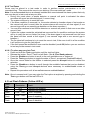
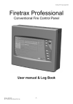
FireTrax VFT-P Quick Start User Operation Guide VI52.1 Firetrax Professional Conventional Fire Control Panel Quick start User Operation Guide Printed : 04/01/2010 Doc : Profesional User Manual quickstart VI52.1.doc -1- FireTrax VFT-P Quick Start User Operation Guide VI52.1 4.0 Using the Fire Panel There are two levels of access control on the Firetrax professional range of fire panels; these are General user and Authorised User both of which have various functions available. 4.1 General User (Access Level 1) Access level 1 is available to members of the general public, or persons having a general responsibility for safety supervision, who might be expected to investigate and initially respond to a fire alarm or a fault warning. Any fire, fault, test or disablements are clearly shown on the led display (see 3.1.2) The only control functions available at Access Level 1 are: Led Lamp and panel buzzer test Muting the panel’s internal buzzer Accessing Level 2 4.1.1 Led Lamp and panel buzzer test To test the panel’s Led display and the internal panel buzzer press the TEST/toggle/2 button, all of the panel’s LED’s should illuminate and the internal buzzer should sound. If any of the LED’s fail to light or the buzzer fails to sound please contact your maintenance company. 4.1.2 Muting the panel’s internal buzzer During a fire or fault condition the fire control panel’s internal buzzer will sound, this may be muted by pressing the Mute Panel Buzzer button which will silence the internal buzzer. This buzzer will resound upon the detection of another fire or fault condition. 4.1.3 Accessing Level 2 To gain access to the Authorised User controls (Access Level 2), press the Code/Exit/4 button until the Access LED starts to flash you may then enter the user code to gain access to level 2 controls. 4.2 Authorised User (Access Level 2) Access Level 2 is available only to authorised users of the fire control panel, who are responsible for safety and who are trained to operate the control panel in the following conditions:a) Quiescent condition b) Fire alarm condition c) Fault warning condition d) Disabled condition An access code (or keyswitch if fitted) is required to gain access to level 2; this is to prevent unauthorised changes to critical parts of the fire alarm system. 4.2.1 Accessing Level 2 (keypad) To gain access to the Authorised User controls (Access Level 2), press the Code/Exit/4 button until the Access LED starts to flash you may then enter the user code 2 1 4 3 the access led will then constant indicating that level 2 access has been granted. 4.2.2 Accessing Level 2 (Keyswitch) If the keyswitch option has been fitted you can gain access to level 2 by inserting and turning the keyswitch a quarter turn clockwise. The access led should go constant to indicate level 2 access is granted. 4.2.3 Exiting Access Level 2 (Keypad) To exit Level 2, you can press the Code/Exit/4 button at any time to exit out of the function that you are currently in and then finally out of Access Level 2 completely. 4.2.4 Exiting Access Level 2 (Keyswitch) Turn the keyswitch a quarter turn anti-clockwise at anytime to exit out of user access level 2. Printed : 04/01/2010 Doc : Profesional User Manual quickstart VI52.1.doc -2- FireTrax VFT-P Quick Start User Operation Guide VI52.1 4.2.5 Silence/Activate Sounders This button can be used to toggle the sounder outputs from Off to On and vice versa. 4.2.5.1 During Quiescent Condition. Pressing the Silence/Activate Sounders button will cause the alarm sounders to sound; this will not cause the fire output to operate. Pressing the Silence/Activate Sounders button again will cause the alarm sounders to silence. This option can be used for fire drill’s or testing the sounders. NOTE: If the sounders have been disabled (See 4.2.8) pressing this button will have no affect. 4.2.5.2 During Fire Condition. In a fire condition the alarm sounders may be silenced by pressing the Silence/Activate Sounders button. The fire output will remain regardless of the condition of the alarm outputs. Upon the detection of any subsequent fire conditions the alarms sounders will resound. 4.2.6 Mute Panel Buzzer During a fire or fault condition the fire control panel’s internal buzzer will sound, this may be muted by pressing the Mute Panel Buzzer button which will silence the internal buzzer. This buzzer will resound upon the detection of another fire or fault condition. 4.2.7 Reset System Once the cause of a fire or fault condition had been investigated and cleared and the alarm sounders have been silenced (During a fire condition) the fire control panel may be reset by pressing the Reset System button. This will cause the system to be reset; all the Led’s will illuminate and the panel buzzer will sound, after a few seconds the system will restart. NOTE: If there are still any zones in fire or fault condition or any outputs still in fault the panel will go back into the alarm state as before the system reset. 4.2.8 Disablements Zones and certain control panel functions can be temporarily disabled; this may be due to routine test on the system or if conditions in certain areas may cause false alarms. The following features and functions may be disabled:Function Zones Earth Alarm Fire Output Action taken by fire panel. Fire and Fault conditions will not be processed Earth faults will be ignored. Alarm sounders will not activate in any condition Fire conditions will not be transmitted to external equipment 4.2.8.1 To Disable or re-enable any of the above functions Press and hold the Disable/Next/1 button until the Disablement Led lights. Release the button. Zone 1 Fault Led will flash. (See 4.3 Led flash patterns) Press the Disable/Next/1 button to scroll to the next available zone or feature or Press the Test/Toggle/2 button to toggle the state of Zone 1 as required (Disabled/Enabled). Once the correct state for the feature is selected press the Accept/3 button to confirm the selection. Press the Disable/Next/1 button to scroll through the available features that can be disabled, using the Test/Toggle/2 and Accept/3 buttons were necessary to enable/disable zones or features. Repeat this procedure until all zones/features are enabled/disabled. Note: Once in access level 2 you may enter the Disablements option at anytime by pressing and holding the Disable/Next/1 button until the disablement LED is lit. Printed : 04/01/2010 Doc : Profesional User Manual quickstart VI52.1.doc -3- FireTrax VFT-P Quick Start User Operation Guide VI52.1 4.2.9 Test Zones Zones may be placed in a test mode in order to perform routine maintenance or to aid commissioning. This converts the zone to non-latching “One man walk test” mode. Note: It is recommended that on an already installed and commissioned fire alarm system that only one zone be put in test mode at any one time. During this mode when a smoke detector or manual call point is activated the alarm sounders will sound an activated signal (1 second ring). The system will then try to reset the zone. if the alarm condition is removed (i.e. the smoke detector’s chamber clears of test smoke or the manual call point is reset) then the system alarms will sound an all clear signal (2 one second rings with a one second gap between on the alarm sounders.) You may then continue to test further detectors or manual call points in that zone or on other zones in test. If when the system resets the activated test zone and the fire condition continues the system will try to reset the zone a further five times; if the alarm signal is not removed from the zone the panel will then sound a fault signal (5 one second rings with a one second gap in between.) The fire panel will continue to try to reset the zone in test; if the zone is still in a fire condition it will continue to give the fault signal. If the fault cannot be rectified the zone must be disabled (see 4.2.8) before you can continue to test any further zones in test mode. 4.2.9.1 To place any zone into Test. Press and hold the Test/Toggle/2 button until the test Led lights. Release the button. Zone 1 Fault Led will flash. (See 4.3 Led flash patterns) Press the Disable/Next/1 button to scroll to the next available zone or feature or Press the Test/Toggle/2 button to toggle the state of Zone 1 as required (Disabled/Enabled). Once the correct state for the feature is selected press the Accept/3 button to confirm the selection. Press the Disable/Next/1 button to scroll through the available features that can be disabled, using the Test/Toggle/2 and Accept/3 buttons were necessary to enable/disable zones or features. Repeat this procedure until all zones/features are enabled/disabled. Note: Once in access level 2 you may enter the Test option at anytime by pressing and holding the Test/Toggle/2 button until the test LED is lit. 4.3 Led Flash Patterns (Yellow LED’s). Flash Type OFF ON Flash Slow Flash Fast Flash Description OFF ON 1 ON / 1 OFF 7 ON / 1 OFF 1 ON / 7 OFF Result Feature/Zone enabled Feature/Zone Disabled FAULT Detected. Cursor position. This flash pattern shows that the feature under the cursor is enabled. Cursor position. This flash pattern shows that the feature under the cursor is disabled. Printed : 04/01/2010 Doc : Profesional User Manual quickstart VI52.1.doc -4-